In situ formation of inorganic healing overlayer for interface-stabilized all-inorganic CsPbIBr2 perovskite solar cells†
Junshuai
Zhang
a,
Qiyao
Guo
a,
Yuanyuan
Zhao
b,
Jialong
Duan
 *a and
Qunwei
Tang
 a
a
aInstitute of Carbon Neutrality, College of Chemical and Biological Engineering, Shandong University of Science and Technology, Qingdao 266590, P. R. China. E-mail: duanjialong@sdust.edu.cn
bCollege of Mechanical and Electronic Engineering, Shandong University of Science and Technology, Qingdao 266590, P. R. China
First published on 22nd November 2022
Abstract
A perovskite layer functionalized to be an outermost screen can strongly affect the capacity of the underlying device to avoid becoming decomposed under external stimuli, and subsequently affect the photovoltaic performance as well. Herein, we report an interface-stabilization strategy for an all-inorganic CsPbIBr2 film involving forming in situ an inorganic ZrO2 layer to solidify the soft perovskite lattice. As a result of defect passivation and self-encapsulation, the best device achieved an enhanced efficiency of up to 10.12%, which was much higher than the 7.47% efficiency for the reference device tested, with prolonged stability under conditions of persistent light irradiation and exposure to air.
Although organic–inorganic hybrid metal halide perovskite solar cells (PSCs) have shown impressive achievements in power conversion efficiency (PCE) with certified values up to 25.7%, their inferior long-term stability remains the largest challenge to their further commercialization.1–4 Considering the volatile nature of their organic species, e.g., CH3NH3+ (MA+), CH3(NH2)2+ (FA+), under high temperature, completely substituting the organic components with inorganic cesium (Cs+) to fabricate all-inorganic PSCs has recently become more prevalent.5–7 Unfortunately, the I-rich perovskite also suffers from serious phase transition when exposed to air.8,9 By contrast, mixed-halide CsPbIBr2 with a bandgap of ∼2.11 eV can effectively balance the often contradictory goals of efficiency and stability, making it one of the top candidates for use as a photovoltaic material in tandem PSCs.10–12 However, its reported efficiency deficit is much higher than that of a traditional hybrid device, with this deficit mainly related to the detrimental nonradiative recombination loss.
Due to the soft-lattice structure of perovskite, many crystallographic defects inevitably form during the rapid crystallization of its film, in particular point defects (such as vacancies, interstitials, and anti-site substitutions) and high-dimensional defects (such as grain boundaries and dislocations), which are regarded as detrimental charge recombination centers and initiation points to degrade the photoactive phase.13 In particular, the top interface is extremely susceptible because of the direct invasion and accumulation of moisture and oxygen. Therefore, many physicochemical strategies for healing the defective layer have been reported, with examples of these strategies including mechanical surface polishing and Lewis acid-base passivation by organic molecules.14–18 It is recognized that depositing a thin 2D perovskite onto a 3D-structured perovskite film can effectively stabilize a defective lattice in a hybrid species, with this stabilization mainly stemming from the incorporation of hydrophobic organic spacers and coordination of the dangling bonds to eliminate defects and block penetration of moisture/oxygen.19,20 Such an approach, however, is difficult to implement for inorganic perovskites because the stronger binding of Cs+ than of organic MA+ or FA+ hinders the cation exchange reaction.21,22 Therefore, it is urgent to develop a new strategy to solidify the interface of all-inorganic PSCs.
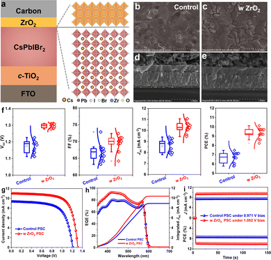
To address the aforementioned issue, we demonstrated in the current work an in situ pyrolytic ZrO2 as a multifunctional capping layer to stabilize the CsPbIBr2 film by directly spin-coating zirconium n-propoxide precursor solution onto the film surface and then subjecting the resulting composite to an annealing treatment under high temperature. In contrast to sensitive organic passivators or low-dimensional perovskites, including an inorganic ZrO2 overlayer benefits the stability of the film by rendering the film insensitive to environmental stresses as a result of the tighter lattice structure and covalent bonds produced. As schematically illustrated in Fig. 1a, the all-inorganic stack included fluorinated tin oxide (FTO), TiO2, CsPbIBr2, ZrO2, and a carbon electrode. Scanning electron microscopy (SEM) images were acquired of the perovskite films to visualize their surface morphologies (Fig. 1b and c); a more compact topography occurred upon incorporation of the interface layer, and did so without destruction of the perovskite crystallization and absorption ability (Fig. S1, ESI†) owing to the filling of trenches. This feature was obvious from the cross-sectional morphologies of the PSCs (Fig. 1d, e and Fig. S2, ESI†), in which a ∼10 nm-thick capping layer was observed. After optimizing the thickness by varying the precursor concentration (Fig. S3, ESI† and Table 1), the photovoltaic current density–voltage (J–V) curves of control and best PSCs were acquired, as shown in Fig. 1g with population statistics shown in Fig. 1f. Upon inserting the capping layer, increases were observed in all of the photovoltaic parameters including PCE, open-circuit voltage (Voc), short-circuit current density (Jsc), and fill factor (FF). Specifically, the resultant carbon-based, all-inorganic CsPbIBr2 PSC delivered a significantly increased PCE of 10.12% with a Voc of 1.310 V, Jsc of 11.027 mA cm−2 and FF of 70.08%. The PCE value was much higher than the 7.47% value for the uncapped device, agreeing well with the integrated current densities from external quantum efficiency (EQE) spectra in Fig. 1h and steady power outputs in Fig. 1i. It should be noted that the efficiency gradually decreased with increasing thickness owing to the insulation of the ZrO2 layer. Given the photogenerated carrier extraction-transfer-recombination behaviors, the performance improvement was mainly ascribed to the boosted charge collection rather than back-recombination at the interface.
| Devices | V oc (V) | J sc (mA cm−2) | FF (%) | PCE (%) |
|---|---|---|---|---|
| Control | 1.211 | 9.395 | 65.66 | 7.47 |
| 0.01 mg mL−1 | 1.282 | 10.502 | 69.33 | 9.33 |
| 0.02 mg mL−1 | 1.310 | 11.027 | 70.08 | 10.12 |
| 0.05 mg mL−1 | 1.254 | 10.045 | 68.27 | 8.64 |
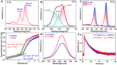
To study the origin of the performance enhancement, specifically to reveal the positive effect of the ZrO2 capping on the perovskite film, we first acquired X-ray photoelectron spectroscopy (XPS) spectra. Two characteristic peaks centered at 182.3 and 184.9 eV in the Zr 3d region of the spectrum of the capped perovskite film demonstrated the successful formation of ZrO2 after the annealing treatment at 200 °C,23 consistent with the detection of an O 1s signal (denoting the Zr–O–Zr and Zr–O–H bonding) (Fig. 2a and b). Moreover, the locations of these Zr 3d peaks at higher binding energies than the Zr 3d5/2 and 3d3/2 peaks of tetragonal ZrO2 species at 182.0 and 184.3 eV23 demonstrated the occurrence of electron donation. Together with the peak difference between the Pb 4f XPS spectra of uncoated and ZrO2-coated perovskite films, shown in Fig. 2c, and the lack of any considerable difference when comparing the corresponding Cs 3d, I 3d and Br 3d spectra, shown in Fig. S4 (ESI†), our results provided confirmatory evidence for the strong interaction between the CsPbIBr2 film and ZrO2 owing to the presence of spontaneous transfer of electrons from ZrO2 to the undercoordinated Pb2+ ions.24 As a result, the defective surface was well healed, significantly eliminating the charge recombination centers. To examine the defect density (Nt) levels in capped and uncapped perovskite films, we took space-charge-limited current (SCLC) measurements based on the structure of FTO/c-TiO2/perovskites/PCBM/carbon. As shown in Fig. 2d, the defect densities were calculated to be 2.14 × 1016 cm−3 and 1.91 × 1016 cm−3 for control and capped perovskite films according to the relationship25VTFL = (eNtL2)/(2εε0), where VTFL represents the trap-filled limit voltage, e the elementary charge, L the thickness of the perovskite film (∼200 nm from SEM images), ε the relative dielectric constant, and ε0 the vacuum permittivity. The reduced Nt was undoubtedly responsible for the higher Voc and Jsc in the PSC, in accordance with the J–V results. Steady photoluminescence (PL) spectra, shown in Fig. 2e, also revealed the remarkably increased PL intensity for the perovskite film coated with the ZrO2 layer, demonstrating the preferred radiative recombination rather than nonradiative recombination as a result of the reduction of detrimental defects.26,27 In other words, the photogenerated carriers survived longer, i.e., with a greater lifetime (τ = 0.945 ns), in the optimal perovskite film than in the control (τ = 0.626 ns) according to recorded time-resolved PL (TRPL) decay curves (Fig. 2f, with the corresponding parameters summarized in Table S1, ESI†). All these results validated the positive effect of the ZrO2 capping layer on the CsPbIBr2 film and the suppression of defect-induced carrier recombination.
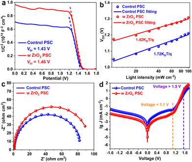
Considering the dependence of photovoltaic performance on the perovskite film quality, the charge recombination dynamics in the PSC was then investigated. As shown in Fig. 3a, capacitance–voltage (C–V) measurements were taken to determine the built-in potential (Vbi) evolution, which determines the level of charge extraction.28 As expected, a larger Vbi was measured for the ZrO2-treated film. This larger Vbi ensured a greater driving force for carrier extraction-transfer. In other words, the nonconductive inorganic ZrO2 has no effect on charge extraction owing to the tunnelling effect.29 Based on the above characterizations, we speculatively proposed an intrinsic mechanism behind the performance enhancement. In the presence of the ZrO2 layer, two undesirable electron recombination channels were closed in the optimal PSC: (i) occurrence of the defect-electron coupling at the perovskite surface was inhibited due to defect passivation by ZrO2; and (ii) the larger Vbi occurring upon ZrO2 treatment hindered the migration of electrons from the perovskite to the carbon electrode to recombine with the hole. We further utilized the dependences of Jsc and Voc on light intensity (I) to investigate the internal recombination mechanism. A linear I ∼ Jsc relationship was found for both devices, as shown in Fig. S5 (ESI†), demonstrating the smooth charge extraction and transport at the PSC interface. However, compared to the 1.72 value of the ideality factor of the control device under the open-circuit condition, that of the device containing the ZrO2 capping was significantly lower, with a value of 1.42, as shown in Fig. 3b, an indicator of suppressed defect-assisted Shockley–Read–Hall (SRH) recombination;30 that is, the corresponding recombination resistance was increased (Fig. 3c) and the lifetime of photogenerated carrier located at the conduction band in the PSC was increased with a slower Voc decay (Fig. S6, ESI†).31 As a result, at voltages <1.1 V, the overall leakage current density of the capped PSC in the dark condition was one order of magnitude lower than that of the control device (Fig. 3d), while higher current density values were found at voltages >1.5 V, mainly attributed to the boosted charge injection,32 and again confirming the positive effect of ZrO2 on healing the defective perovskite surface.
 | ||
| Fig. 3 (a) C–V curves, (b) dependence of Voc on light intensity, (c) EIS spectra, and (d) dark J–V curves of control and ZrO2-capped CsPbIBr2 PSCs. | ||
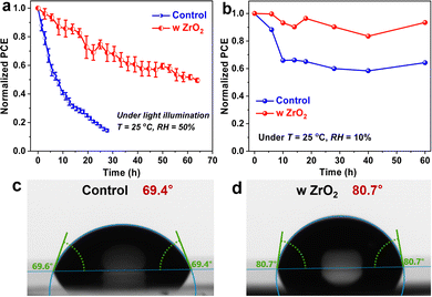
Finally, we aged the unencapsulated control and ZrO2-capped PSCs under persistent light irradiation and dry air at a temperature (T) of 25 °C and relative humidity (RH) of 10%, which was controlled by using a drybox with an automatic adjustment function. As shown in Fig. 4a, b and Fig. S7 (ESI†), the efficiency level of the latter device remained at 50% and 90% of the initial efficiency after operation over 65 hours and storage over 60 days, respectively, while the performance of the control device degraded more sharply. Considering the higher contact angle measured for the capped film than for the uncapped one (Fig. 4c and d), the improved stability of the capped device can be attributed to the self-encapsulation effect of the inert ZrO2 layer on the underlying perovskite film,33–35 inhibiting the direct penetration of external moisture/oxygen into the perovskite lattice that would have otherwise deteriorated the photoactive phase.
In summary, we demonstrated an effective and feasible strategy to heal the defective surface of an inorganic perovskite film by in situ forming an inorganic ZrO2 covering layer to overcome the bottleneck in converting the 3D crystal into a 2D structure. As a result of the migration of electrons from ZrO2 to the perovskite surface, the detrimental defects were passivated, leading to suppressed nonradiative recombination. Finally, the best device achieved a significantly increased PCE of up to 10.12% for a carbon-based, fully inorganic CsPbIBr2 PSC. In addition to efficiency, more importantly, the robust interface separated perovskite from environmental moisture/oxygen stresses owing to the self-encapsulation of the inert ZrO2 layer, leading to a remarkable enhancement of the durability of the PSC.
The authors gratefully acknowledge financial support provided by the National Natural Science Foundation of China (22109053), the Guangdong Basic and Applied Basic Research Foundation (2020A1515110548), the Guangzhou Science and Technology Planning Project (202102020775, 202102010091), and National Key Research and Development Program of China (2021YFE0111000).
Conflicts of interest
There are no conflicts to declare.Notes and references
- A. Kojima, K. Teshima, Y. Shirai and T. Miyasaka, J. Am. Chem. Soc., 2009, 131, 6050–6051 CrossRef CAS PubMed.
- Y. Zhao, F. Ma, Z. Qu, S. Yu, T. Shen, H.-X. Deng, X. Chu, X. Peng, Y. Yuan, X. Zhang and J. You, Science, 2022, 377, 531–534 CrossRef CAS PubMed.
- N. Li, X. Niu, Q. Chen and H. Zhou, Chem. Soc. Rev., 2020, 49, 8235–8286 RSC.
- Y. Zhou, L. M. Herz, A. K.-Y. Jen and M. Saliba, Nat. Energy, 2022, 7, 794–807 CrossRef CAS.
- J. Zhang, G. Hodes, Z. Jin and S. (Frank) Liu, Angew. Chem., Int. Ed., 2019, 58, 15596–15618 CrossRef CAS PubMed.
- Y. Cui, J. Shi, F. Meng, B. Yu, S. Tan, S. He, C. Tan, Y. Li, H. Wu, Y. Luo, D. Li and Q. Meng, Adv. Mater., 2022, 34, 2205028 CrossRef CAS PubMed.
- J. Liang and Y. B. Qi, Mater. Today Nano, 2021, 16, 100143 CrossRef CAS.
- H. Yao, Z. Li, C. Shi, Y. Xu, Q. Wang, Z. Li, G. Peng, Y. Lei, H. Wang, Z. Ci and Z. Jin, Adv. Funct. Mater., 2022, 32, 2205029 CrossRef CAS.
- Y. Lei, Z. Li, H. Wang, Q. Wang, G. Peng, Y. Xu, H. Zhang, G. Wang, L. Ding and Z. Jin, Sci. Bull., 2022, 67, 1352–1361 CrossRef CAS.
- W. Zhu, Z. Zhang, D. Chen, W. Chai, D. Chen, J. Zhang, C. Zhang and Y. Hao, Nano-Micro Lett., 2020, 12, 87 CrossRef CAS PubMed.
- J. Wang, X. Wu, Y. Liu, Q. Xue, H.-L. Yip, A. K. Y. Jen and Z. Zhu, Energy Technol., 2021, 9, 2100562 CrossRef CAS.
- Q. Liu, J. Qiu, X. Yan, Y. Fei, Y. Qiang, Q. Chang, Y. Wei, X. Zhang, W. Tian, S. Jin, Z. Yu and L. Sun, J. Energy Chem., 2022, 74, 387–393 CrossRef CAS.
- Y. Zheng, X. Yang, R. Su, P. Wu, Q. Gong and R. Zhu, Adv. Funct. Mater., 2020, 30, 2000457 CrossRef CAS.
- Y. Xu, L. Zhai, L. Sun, J. Wang, X. Tan, H. Huang, Y. Wang, G. Yang, K. Jiang, Y. Yang, L. Zhang, Z. Tan and C. Zou, Chem. Commun., 2022, 58, 7132–7135 RSC.
- S. Chen, Y. Liu, X. Xiao, Z. Yu, Y. Deng, X. Dai, Z. Ni and J. Huang, Joule, 2020, 4, 2661–2674 CrossRef CAS.
- A. Yusoff, M. Vasilopoulou, D. G. Georgiadou, L. C. Palilis, A. Abate and M. K. Nazeeruddin, Energy Environ. Sci., 2021, 14, 2906–2953 RSC.
- R. Zhao, L. Xie, R. Zhuang, T. Wu, R. Zhao, L. Wang, L. Sun and Y. Hua, ACS Energy Lett., 2021, 6, 4209–4219 CrossRef CAS.
- G. Liu, Y. Zhong, W. Feng, M. Yang, G. Yang, J.-X. Zhong, T. Tian, J.-B. Luo, J. Tao, S. Yang, X.-D. Wang, L. Tan, Y. Chen and W.-Q. Wu, Angew. Chem., Int. Ed., 2022, 61, e202209464 CAS.
- D. Zhao, D. Gao, X. Wu, B. Li, S. Zhang, Z. Li, Q. Wang, Z. Wu, C. Zhang, W. C. H. Choy, X. Zhong, Q. He and Z. Zhu, Adv. Energy Mater., 2022, 34, 2204661 CAS.
- M. A. Mahmud, T. Duong, J. Peng, Y. Wu, H. Shen, D. Walter, H. T. Nguyen, N. Mozaffari, G. D. Tabi, K. R. Catchpole, K. J. Weber and T. P. White, Adv. Funct. Mater., 2022, 32, 2009164 CrossRef CAS.
- X. Zhao, T. Liu, Q. C. Burlingame, T. Liu, R. HolleyIII, G. Cheng, N. Yao, F. Gao and Y.-L. Loo, Science, 2022, 377, 307–310 CrossRef CAS PubMed.
- Y. Wang, T. Zhang, M. Kan and Y. Zhao, J. Am. Chem. Soc., 2018, 140, 12345–12348 CrossRef CAS PubMed.
- H. Li, Y. Wu, C. Li, Y. Gong, L. Niu, X. Liu, Q. Jiang, C. Sun and S. Xu, Appl. Catal., B, 2019, 251, 305–312 CrossRef CAS.
- Y. Wang, H. Yang, K. Zhang, M. Tao, M. Li and Y. Song, ACS Energy Lett., 2022, 7, 3646–3652 CrossRef CAS.
- S. Wang, H. Guo, J. Wu, Y. Lei, X. Li, Y. Fang, Y. Dai, W. Xiang and Y. Lin, Chem. Commun., 2022, 58, 8384–8387 RSC.
- S. Wang, X. Zhang, W. Zhu, Z. Tang, J. Liu, H. Zhang, L. Ding and F. Hao, Appl. Surf. Sci., 2022, 602, 154393 CrossRef CAS.
- Q. Guo, J. Duan, J. Zhang, Q. Zhang, Y. Duan, X. Yang, B. He, Y. Zhao and Q. Tang, Adv. Mater., 2022, 34, 2202301 CrossRef CAS PubMed.
- H. Wang, F. Ye, J. Liang, Y. Liu, X. Hu, S. Zhou, C. Chen, W. Ke, C. Tao and G. Fang, Joule, 2022 DOI:10.1016/j.joule.2022.10.001.
- J. Li, F. Yan, P. Yang, Y. Duan, J. Duan and Q. Tang, Sol. RRL, 2021, 6, 2100791 CrossRef.
- B. Li, Z. Li, X. Jiang, Z. Wang, Y. Rao, C. Zhang, M. Zhu, L. Zhang, L. Wen, S. K. So, Y. Zhou, S. Pang and Z. Zhou, Appl. Surf. Sci., 2022, 603, 154410 CrossRef CAS.
- Y. Xie, J. Feng, M. Chen, X. Zhu, Y. Zhou, Z. Li, D. Yang and S. F. Liu, ACS Appl. Energy Mater., 2022, 5, 8034–8041 CrossRef CAS.
- F. Yan, P. Yang, J. Li, Q. Guo, Q. Zhang, J. Zhang, Y. Duan, J. Duan and Q. Tang, Chem. Eng. J., 2022, 430, 132781 CrossRef CAS.
- T. Tian, J.-X. Zhong, M. Yang, W. Feng, C. Zhang, W. Zhang, Y. Abdi, L. Wang, B.-X. Lei and W.-Q. Wu, Angew. Chem., Int. Ed., 2021, 60, 23735–23742 CrossRef CAS PubMed.
- Y. Zhan, J. Peng, C. Cao and Q. Cheng, Nano Energy, 2022, 101, 107575 CrossRef CAS.
- T. Liu, Y. Zhou, Z. Li, L. Zhang, M.-G. Ju, D. Luo, Y. Yang, M. Yang, D. H. Kim, W. Yang, N. P. Padture, M. C. Beard, X. C. Zeng, K. Zhu, Q. Gong and R. Zhu, Adv. Mater., 2018, 8, 1800232 Search PubMed.
Footnote |
| † Electronic supplementary information (ESI) available. See DOI: https://doi.org/10.1039/d2cc05993b |
| This journal is © The Royal Society of Chemistry 2022 |


