Introduction of metal precursors by electrodeposition for the in situ growth of metal–organic framework membranes on porous metal substrates†
Sheng
Zhou
,
Yanying
Wei
*,
Libin
Zhuang
,
Liang-Xin
Ding
and
Haihui
Wang
 *
*
School of Chemistry & Chemical Engineering, South China University of Technology, No. 381 Wushan Road, Guangzhou 510640, China. E-mail: ceyywei@scut.edu.cn; hhwang@scut.edu.cn
First published on 28th December 2016
Abstract
We report here a facile and efficient electrodeposition method to modify inexpensive porous stainless-steel nets for use as substrates in the in situ growth of metal–organic framework membranes, such as ZIF-8, ZIF-67 and HKUST-1. Using this method, different metal precursors can be electrodeposited depending on the central metals required in the target metal–organic frameworks. The inorganic modifiers prepared by this approach are sufficiently reactive for the one-step growth of continuous metal–organic framework membranes; their reactivity is comparable with that of organic functional groups. The procedure is also green and cost-effective, which is promising for use in large-scale production.
Membrane separation is a promising technology for industrial-scale separation and purification processes as a result of its low consumption of energy.1 Metal–organic frameworks (MOFs) have great potential for use as membranes in separation processes because their pore size can be tuned and they have highly designable structures and adsorption properties.2 The preparation of supported MOF membranes has attracted increasing attention in separation technology.3 Shekhah et al.4 used a stepwise layer-by-layer (LBL) growth method to prepare MOF thin films of HKUST-1 and zeolitic imidazolate framework 8 (ZIF-8) directly on confined surfaces and demonstrated the potential of the LBL method in the controlled growth of MOF thin films on different substrates. They also developed a liquid phase epitaxy method for the construction of oriented ZIF-8 thin films on functionalized surfaces5 and paved the way for the preparation of ZIF-8 thin films on porous substrates. They also succeeded in preparing ultra-thin and defect-free ZIF-8 membranes on porous supports for use in gas separation.6
Although various methods have been used to fabricate MOF membranes, it is still challenging to build a versatile platform for the in situ growth of MOF membranes.7 There have been many reports on the modification of substrates with organic functional groups prior to the in situ growth of MOF membranes. Caro and coworkers used 3-aminopropyltriethoxysilane as a covalent linker to grow a series of ZIF membranes (ZIF-22,8 ZIF-90 (ref. 9) and ZIF-95 (ref. 10)). Polydopamine was shown to be powerful and effective for the fabrication of MOF membranes, including ZIF-8,11 ZIF-90 (ref. 11) and ZIF-100.12 Many other organic compounds, such as polyethyleneimine,13 poly(methyl methacrylate)14 and polyaniline15 have been used as reactive linkers to modify substrates.
Inorganic modifiers are more environmentally friendly than organic modifiers, however. Qiu and coworkers prepared Ni-based and Cu-based MOF membranes on nickel nets16 and copper nets17via a twin copper source method. Neelakanda et al.18 used a double zinc source method to manufacture ZIF-8 membranes on a polymeric substrate. Zhang et al.19 grew ZIF-8 membranes on ZnO nanorod modified supports via a hydrothermal method. Liu et al.20 used Zn-based layered double hydroxide buffer layers as surface modifiers to provide active sites for the nucleation of Zn-based MOF crystals for membrane growth.
There are still some challenges in the development of inorganic modifiers, however, which urgently need to be overcome. The traditional methods for the introduction of inorganic modifiers, such as calcination21 or hydrothermal treatment, are both complicated and time consuming.19,20 In addition, the inorganic compounds currently used as modifiers are not as reactive as organic modifiers, which makes it difficult to form continuous MOF membranes.19 Only one kind of inorganic modifier can be used for metal-based MOF membrane growth, resulting in a lack of versatility and commonality. Therefore it is desirable to develop a simple and universal strategy to prepare inorganic surface modifiers with excellent reactivity for use in different kinds of metal-based MOF membranes.
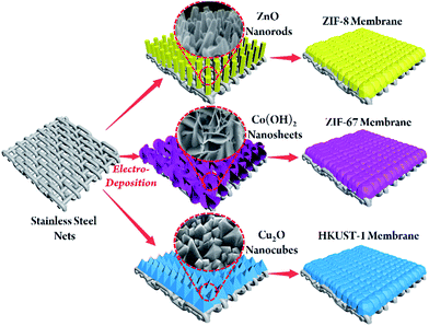
Inspired by electrochemical applications, we developed a novel electrodeposition-assisted strategy to modify substrates to give a versatile platform for the in situ growth of various MOF membranes. Electrodeposition has attracted much attention in the application of electrochemistry.22 As a result of the wide range of metals available and the accelerated rate of formation of the metal precursors by the addition of a small current, electrodeposition can be used as a facile and effective method of preparing various metal oxides/hydroxides on conductive substrates.22 We chose stainless-steel nets (SSNs) as the substrate as they are inexpensive and easily welded. The preparation concept is shown schematically in Fig. 1. A metal oxide/hydroxide with a morphology exactly corresponding to the metal centres of the targeted MOFs is introduced onto the SSN via electrodeposition. For example, ZnO nanorods, Co(OH)2 nanosheets and Cu2O nanocubes can be electrodeposited onto substrates quickly and provide active sites for the crystallization of Zn–ZIF-8, Co–ZIF-67 and Cu–HKUST-1, followed by in situ growth to form continuous MOF membranes.
 | ||
| Fig. 1 Schematic illustration of the in situ growth of three different MOF membranes on supports modified by electrodeposition. | ||
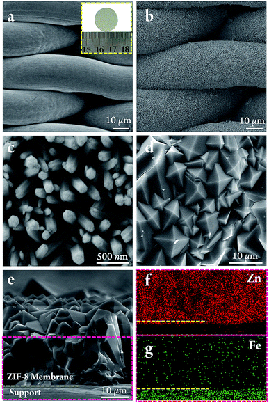
The SSN substrate had a uniform pore size of 30 × 6 μm, the microstructure of which is shown in Fig. 2a. The SSN modified by ZnO nanorods was prepared by immersing the pre-cleaned SSN into an aqueous mixture containing Zn(NO3)2·6H2O and NH4NO3 (see ESI†). With the application of a constant current, the concentration of OH− near the SSN increased due to the electrolysis of water (eqn (1)) and the precursor of Zn(OH)2 was initially formed on the substrates as in eqn (2). As a result of the low stability of Zn(OH)2 under these conditions, it transformed to ZnO through the dehydration reaction in eqn (3). Fig. 2c shows that the ZnO nanorods were closely aligned on the surface of the SSN fibres. The pure phase of ZnO was confirmed by XRD (Fig. S1†). The whole process was environmentally friendly and uniform modification was complete within 90 min.
| H2O → H+ + OH− | (1) |
| Zn2+ + 2OH− → Zn(OH)2 | (2) |
| Zn(OH)2 → ZnO + H2O | (3) |
The ZnO nanorods prepared by electrodeposition had a reactivity comparable with that of commonly used organic modifiers. Thus the SSN modified with ZnO nanorods was used directly for the in situ growth of ZIF-8 membranes. Fig. 2d and e show that there were no defects or pinholes in the top view and cross-sectional images.
Zhang et al.19 have previously reported the preparation of ZIF-8 membranes on substrates modified with ZnO nanorods, but the ZnO grown by a seeding procedure under hydrothermal conditions was not sufficiently reactive and required an additional step of activation to create nucleation sites on the surface of the ZnO nanorods. No pre-activation treatment was required for the ZnO nanorods in our study and well-intergrown ZIF-8 membranes were obtained in only one step within 10 h. The enhancement in the reactivity of the ZnO nanorods can be explained by the low synthesis temperature and the presence of intrinsic defects in the ZnO nanorods arising from the electrodeposition strategy.
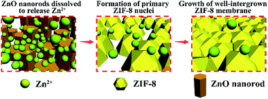
The proposed in situ growth process of ZIF-8 membranes is shown schematically in Fig. 3. The ZnO nanorods served as sacrificial precursors for the in situ nucleation of ZIF-8 crystals because the ZnO nanorods ultimately disappeared, as shown in the membrane cross-section image (Fig. 2e) and XRD patterns (Fig. S1†). At the initial stage, the ZnO nanorods, as amphoteric oxides, dissolved and released Zn2+ in the weak alkaline reaction system. Zn2+ and 2-methylimidazole then coordinated immediately and anchored on the SSN substrates by forming ZIF-8. It is crucial to balance the reaction rates between the two processes of Zn2+ release from ZnO nanorods and Zn2+ consumption during the formation of ZIF-8, otherwise the mismatched reaction rates block the in situ crystallization of ZIF-8 nuclei on the surface of the substrates. The ZIF-8 crystals at the position of the ZnO nanorods can be regarded as “in situ seeds” because they behave as nucleation sites for the subsequent intergrowth of dense ZIF-8 membranes. The final XRD patterns of the ZIF-8 membrane (Fig. S1†) matched well with the simulated ZIF-8 crystals, indicating the successful synthesis of pure phase membranes. By contrast, when unmodified bare SSNs were used, only loosely distributed ZIF-8 crystals were grown on the SSN substrates (Fig. S2†), which demonstrates the requirement for, and advantages of, modification with the ZnO nanorods.
The gas separation performance of the as-synthesized ZIF-8 membrane is shown in Fig. 4. For a 1![[thin space (1/6-em)]](https://www.rsc.org/images/entities/char_2009.gif) :
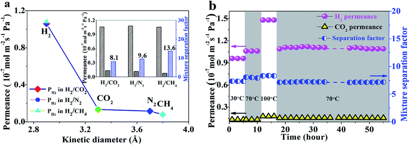
:![[thin space (1/6-em)]](https://www.rsc.org/images/entities/char_2009.gif) 1 binary gas mixture as a feed gas at 70 °C and 1 bar, the permeation of H2 was 1.1 × 10⁻⁷ mol m−2 s−1 Pa−1, much higher than that of other gases such as CO2, N2 and CH4, and a clear cut-off was seen. CH4 molecules, with a kinetics diameter (0.38 nm) larger than the pore size of ZIF-8 (0.34 nm), could also pass through the membranes due to the flexibility of the framework.23 Thus the separation factors of the H2/CO2, H2/N2 and H2/CH4 gas pairs were 8.1, 9.6 and 13.6, respectively, much higher than their corresponding Knudsen coefficients and comparable with those of many other ZIF-8 membranes (Table S1†).24 The ZIF-8 membrane also showed excellent stability during long-term operation, even after series changes in temperature (Fig. 4b).
1 binary gas mixture as a feed gas at 70 °C and 1 bar, the permeation of H2 was 1.1 × 10⁻⁷ mol m−2 s−1 Pa−1, much higher than that of other gases such as CO2, N2 and CH4, and a clear cut-off was seen. CH4 molecules, with a kinetics diameter (0.38 nm) larger than the pore size of ZIF-8 (0.34 nm), could also pass through the membranes due to the flexibility of the framework.23 Thus the separation factors of the H2/CO2, H2/N2 and H2/CH4 gas pairs were 8.1, 9.6 and 13.6, respectively, much higher than their corresponding Knudsen coefficients and comparable with those of many other ZIF-8 membranes (Table S1†).24 The ZIF-8 membrane also showed excellent stability during long-term operation, even after series changes in temperature (Fig. 4b).
To check the general application of the strategy by electrodeposition modification, another two MOF membranes with different metal centres, including Co–ZIF-67 and Cu–HKUST-1, were also successfully fabricated using a similar route. The performance of both membranes were tested in the separation of different gases.
For the preparation of ZIF-67 membranes, flower-like Co(OH)2 nanosheets were first introduced onto the SSNs by electrodeposition within 40 minutes (Fig. S3b†). In contrast with the full self-sacrifice of ZnO nanorods during ZIF-8 membrane growth, the Co(OH)2 nanosheets were not completely consumed (Fig. S3e†). There was still a visible layer of Co(OH)2 with a thickness of around 3 μm between the substrate and the ZIF-67 membrane. The existence of Co(OH)2 buffer layer was confirmed by energy-dispersive X-ray spectroscopy (EDXS) of the cross-section of the ZIF-67 membrane, where O was only distributed in the intermediate buffer layer and N was only distributed in the upper layer of ZIF-67 (Fig. S3f†). However, the modifier was still highly reactive and the in situ growth of the ZIF-67 membrane was completed in one step without any activation treatment. The XRD patterns in Fig. S4† further confirm the formation of the ZIF-67 phase. The ZIF-67 membrane showed an excellent gas separation performance and the ideal separation factors of H2/CO2, H2/N2 and H2/CH4 were 8.2, 9.0 and 12.4, respectively, at room temperature (Fig. S5†).
For the preparation of the HKUST-1 membrane with a central Cu2+, the electrodeposited metal precursor of Cu2O in a different valence state also assisted the in situ growth of the HKUST-1 membrane. The microstructure of the electrodeposited Cu2O nanocubes is shown in Fig. S6b† and the pure phase was confirmed by XRD (Fig. S7†). The SEM images in Fig. S6† show the successful formation of the HKUST-1 membrane after in situ growth and the pure phase was also confirmed by XRD (Fig. S7†). The as-prepared HKUST-1 membrane was tested for gas separation and an ideal separation factor of 9.7 for H2/CO2 was obtained, indicating that the membrane was intact and well grown (Fig. S8†).
Conclusions
An efficient electrodeposition strategy is proposed for the introduction of diverse metal clusters into inexpensive SSN substrates. These metal clusters universally act as inorganic modifiers for the subsequent facile in situ growth of the MOF membranes. The fast and mild process of modification assisted by electrodeposition is promising for scaled-up production as well as low-cost manufacturing. The excellent reactivity of these metal oxide/hydroxide precursors arising from electrodeposition plays a vital part in the one-step in situ synthesis of various MOF membranes. The proposed electrodeposition-assisted strategy simplifies the procedure and can be applied to the preparation of different kinds of metal-centred MOF membranes.Acknowledgements
We gratefully acknowledge the funding from the Natural Science Foundation of China for Distinguished Young Scholars of China (no. 21225625), the Natural Science Foundation of China (21536005, 51621001) and the Natural Science Foundation of the Guangdong Province (2014A030312007).Notes and references
- N. W. Ockwig and T. M. Nenoff, Chem. Rev., 2007, 107, 4078 CrossRef CAS PubMed.
- (a) O. Shekhah, J. Liu, R. Fischer and C. Wöll, Chem. Soc. Rev., 2011, 40, 1081 RSC; (b) J. Yao and H. Wang, Chem. Soc. Rev., 2014, 43, 4470 RSC; (c) H. Furukawa, K. E. Cordova, M. O'Keeffe and O. M. Yaghi, Science, 2013, 341, 1230444 CrossRef PubMed.
- H. Bux, F. Liang, Y. Li, J. Cravillon, M. Wiebcke and J. Caro, J. Am. Chem. Soc., 2009, 131, 16000 CrossRef CAS PubMed.
- O. Shekhah, L. Fu, R. Sougrat, Y. Belmabkhout, A. J. Cairns, E. P. Giannelis and M. Eddaoudi, Chem. Commun., 2012, 48, 11434 RSC.
- O. Shekhah and M. Eddaoudi, Chem. Commun., 2013, 49, 10079 RSC.
- O. Shekhah, R. Swaidan, Y. Belmabkhout, M. Du Plessis, T. Jacobs, L. J. Barbour, I. Pinnau and M. Eddaoudi, Chem. Commun., 2014, 50, 2089 RSC.
- S. Qiu, M. Xue and G. Zhu, Chem. Soc. Rev., 2014, 43, 6116 RSC.
- A. Huang, H. Bux, F. Steinbach and J. Caro, Angew. Chem., 2010, 122, 5078 CrossRef.
- A. Huang, W. Dou and J. Caro, J. Am. Chem. Soc., 2010, 132, 15562 CrossRef CAS PubMed.
- A. Huang, Y. Chen, N. Wang, Z. Hu, J. Jiang and J. Caro, Chem. Commun., 2012, 48, 10981 RSC.
- Q. Liu, N. Wang, J. r. Caro and A. Huang, J. Am. Chem. Soc., 2013, 135, 17679 CrossRef CAS PubMed.
- N. Wang, Y. Liu, Z. Qiao, L. Diestel, J. Zhou, A. Huang and J. Caro, J. Mater. Chem. A, 2015, 3, 4722 CAS.
- Y. S. Li, H. Bux, A. Feldhoff, G. L. Li, W. S. Yang and J. Caro, Adv. Mater., 2010, 22, 3322 CrossRef CAS PubMed.
- T. Ben, C. Lu, C. Pei, S. Xu and S. Qiu, Chem.–Eur. J., 2012, 18, 10250 CrossRef CAS PubMed.
- J. Fu, S. Das, G. Xing, T. Ben, V. Valtchev and S. Qiu, J. Am. Chem. Soc., 2016, 138, 7673 CrossRef CAS PubMed.
- Z. Kang, M. Xue, L. Fan, L. Huang, L. Guo, G. Wei, B. Chen and S. Qiu, Energy Environ. Sci., 2014, 7, 4053 CAS.
- H. Guo, G. Zhu, I. J. Hewitt and S. Qiu, J. Am. Chem. Soc., 2009, 131, 1646 CrossRef CAS PubMed.
- P. Neelakanda, E. Barankova and K.-V. Peinemann, Microporous Mesoporous Mater., 2016, 220, 215 CrossRef CAS.
- X. Zhang, Y. Liu, S. Li, L. Kong, H. Liu, Y. Li, W. Han, K. L. Yeung, W. Zhu and W. Yang, Chem. Mater., 2014, 26, 1975 CrossRef CAS.
- (a) Y. Liu, N. Wang, J. H. Pan, F. Steinbach and J. Caro, J. Am. Chem. Soc., 2014, 136, 14353 CrossRef CAS PubMed; (b) Y. Liu, J. H. Pan, N. Wang, F. Stein-bach, X. Liu and J. Caro, Angew. Chem., 2015, 127, 3071 CrossRef.
- X. Zhang, Y. Liu, L. Kong, H. Liu, J. Qiu, W. Han, L.-T. Weng, K. L. Yeung and W. Zhu, J. Mater. Chem. A, 2013, 1, 10635 CAS.
- (a) G. H. A. Therese and P. V. Kamath, Chem. Mater., 2000, 12, 1195 CrossRef CAS; (b) L.-X. Ding, A.-L. Wang, G.-R. Li, Z.-Q. Liu, W.-X. Zhao, C.-Y. Su and Y.-X. Tong, J. Am. Chem. Soc., 2012, 134, 5730 CrossRef CAS PubMed.
- D. Fairen-Jimenez, S. Moggach, M. Wharmby, P. Wright, S. Parsons and T. Duren, J. Am. Chem. Soc., 2011, 133, 8900 CrossRef CAS PubMed.
- (a) J. Yao, D. Dong, D. Li, L. He, G. Xu and H. Wang, Chem. Commun., 2011, 47, 2559 RSC; (b) K. Tao, L. Cao, Y. Lin, C. Kong and L. Chen, J. Mater. Chem. A, 2013, 1, 13046 RSC; (c) J. Li, W. Cao, Y. Mao, Y. Ying, L. Sun and X. Peng, CrystEngComm, 2014, 16, 9788 RSC; (d) Y. Hu, J. Wei, Y. Liang, H. Zhang, X. Zhang, W. Shen and H. Wang, Angew. Chem., Int. Ed., 2016, 55, 2048 CrossRef CAS PubMed.
Footnote |
| † Electronic supplementary information (ESI) available: Experimental procedures, characterization data. See DOI: 10.1039/c6ta09469d |
| This journal is © The Royal Society of Chemistry 2017 |


