 Open Access Article
In situ anchor of Na2Ti3O7 in nitrogen-rich carbon hollow red blood cell-like structure as a 0D-3D hierarchical electrode material for efficient electrochemical desalination†
Yingying
Zhang
,
Xiaogeng
Feng
,
Yuejiao
Wang
,
Weijun
Shan
,
Zhenning
Lou
and
Ying
Xiong
 *
*
College of Chemistry, Key Laboratory of Rare-scattered Elements of Liaoning Province, Liaoning University, Shenyang 110036, P. R. China. E-mail: xiongying_1977@hotmail.com
First published on 18th March 2022
Abstract
Reasonable design of the structure and complementary compounding of electrode materials is helpful to enhance capacitive deionization (CDI) performance. Herein, a novel 0D–3D hierarchical electrode material containing Na2Ti3O7 nanoparticles anchored at hollow red blood cell (HRBC)-like nitrogen-rich carbon (HRBC-NTO/N-C-60) was prepared via selective protection, pyrolysis, and alkalization. Specifically, a HRBC-like NH2-MIL-125-based material (HRBC-MOF-60) was first constructed by a selective protection approach of tannic acid (TN), which addresses the shortcomings of using sacrificial templates or corrosive agents. Afterwards, HRBC-NTO/N-C-60 was obtained in situ by annealing and alkalization of HRBC-MOF-60. The nitrogen-rich carbon with a HRBC-like structure has the ability to rapidly transport electrons, and its porous structure enables remarkable charge transfer. Benefiting from the grafted 3D N-doped porous carbon with a HRBC-like structure, well-dispersed 0D Na2Ti3O7 nanoparticles, and satisfactory bonding effects, HRBC-NTO/N-C-60 exhibited high specific capacitance and fast ionic and electronic diffusion kinetics. Moreover, HRBC-NTO/N-C-60 was well-suited for desalination by functioning as a cathode material for capacitive deionization (CDI), and delivering a high desalination capacity of 66.8 mg g−1 in 200 mg L−1 NaCl solution at 1.4 V. This work introduces an excellent high-performance candidate for electrochemical deionization as well as affording afflatus for accurately inventing OD-3D hierarchical materials with hollow structures.
1. Introduction
With the ever-increasing world population and ongoing climate change, the demand for clean water is greater than the available freshwater supply, which is becoming insufficient due to rapid depletion by humans.1,2 Desalination of salt water and brackish water is a crucial approach to address the freshwater crisis because it will promote the sustainable development of human society.3,4 Among various desalination technologies, capacitive deionization (CDI) has been identified as a potentially promising technology in view of its low cost and eco-friendliness as compared with the traditional desalination technologies of reverse osmosis and thermal distillation.5,6In the field of CDI, the creation of advanced cathode materials is one of the most efficient ways to enhance desalination performance. Faradaic electrodes outperform carbon-based materials as cathode alternatives, mechanistically working via faradaic reactions.7,8 Among various potential faradaic electrodes, the performance of transition oxometallates (TOMS) for use in electrochemical desalination has been proven to be superior to that of metal oxides, which are their counterpart.9 Superior to pure TOMS, TOMS nanoparticles anchored in carbon skeletons or coated with carbon can decrease the aggregation of nanoparticles, increase the ion diffusion efficiency, enhance electrical conductivity, and thus boost desalination performance.10,11
Programming a suitable structure to assume the function of an electrode material is a great strategy to improve its electrochemical performance.12,13 Hollow spherical structures have been extensively applied in many electrochemical correlative fields because of their large surface area and ample active sites. However, this structure is in need of improvement because the relatively low volumetric energy densities result in much unemployed space between the spheres even when those spheres are ideally arranged, and such large hollow voids are undesirable for practical application.14 Designs of complex hollow structures, such as that of a hollow red blood cell (HRBC), could partly overcome the volume loss problem of hollow spherical structures.15 A packing arrangement with greater density than that of spheres can be attained with HRBC structures, and such arrangements are nearly identical to that of red blood cells (RBCs, erythrocytes) stacked up one by one, thus resulting in a greater amount of active material per unit volume.16 As illustrated in Fig. S1,† a greater number of RBC-like particles can be closely packed within a given amount of space compared to hollow spheres. Thus, HRBC structures exhibit remarkable performance that differs from their hollow sphere counterparts with the advantages of high packing densities and high loading capacity. In this context, the manufacture of electrode materials with HRBC structures might be a viable approach to increase desalination performance.
At present, numerous methods, including the hard-template method, soft-template method, and self-template method, have been used for preparing hollow structures that can be used to improve sodium ion storage performance. Compared to the hard- and soft-template methods, it is thought that the operation of the self-template method is more facile,17 and thus there has been greater interest in the use of self-template methods. However, it is greatly fulfilling yet terribly challenging to prepare a precursor with HRBC structures and tailored components.
Metal–organic frameworks (MOFs) have been widely applied as self-templates for the preparation of metal/metal oxide-carbon composites. In general, MOF-derived materials usually possess high porosity and high surface area,18 which are conducive to metal components evenly scattered on a carbon frame. Furthermore, during annealing processes, organic ligands containing N atoms easily produce N-doped porous carbon. Nitrogen-rich carbon is beneficial for increasing the speed of charge transfer.19 In addition, composites with complex structures (such as hollow spheres or core–shells) of metal/metal oxide with carbon can be prepared using MOFs with corresponding structures as a template.20 Therefore, MOFs, which are well-known precursors, are suitable for constructing materials with HRBC structures. The fabrication of MOFs with HRBC structures, however, has rarely been reported because of their rigidity and low mechanical stability.
Herein, we propose a novel method for constructing zero-dimensional (0D) Na2Ti3O7 (NTO, titanate) nanoparticles anchored on hollow RBC-like nitrogen-rich carbon (HRBC-NTO/N-C-60). Concretely, this procedure is meant to achieve HRBC-MOF-60 by a one-step hydrothermal synthesis with tannic acid (TN) as the selective protective reagent, followed by sequential pyrolysis and alkalization reaction to prepare HRBC-NTO/N-C-60. Encouragingly, a CDI system assembled with HRBC-NTO/N-C-60 as the cathode and Ag@rGO as the anode achieved high desalination (66.8 mg g−1, 8.9 mg g−1 min−1), which can be attributed to its unique hollow RBC-like architecture and satisfactory components. Consequently, this study provides an access path to prepare TOMS/C composites with hollow RBC-like structures and provides an additional choice among the electrode materials currently available for desalination.
2. Results and discussion
2.1. Characterization of HRBC-MOF-x self-template
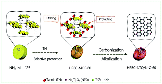
Fig. 1 describes the general course of HRBC-MOF-60 production. Specifically, cake-like NH2-MIL-125 (Fig. 2a) was first prepared, and then hydrothermally reacted with TN at 150 °C. The TN attaches on the surface of the cake-like NH2-MIL-125 (with a diameter of approximately 4 nm), which originates from their abundant hydroxyl groups and large molecular weight (average molecular weight of 1700 Da). Free protons released from TN enter into the central region of the cake-like NH2-MIL-125 and destroy weak Ti–O bonding. Thus, TN protects the surface of cake-like NH2-MIL-125, while the inner part of the cakes were etched, which ultimately forms a NH2-MIL-125-based self-template (HRBC-MOF-x, where x represents the hydrothermal reaction time).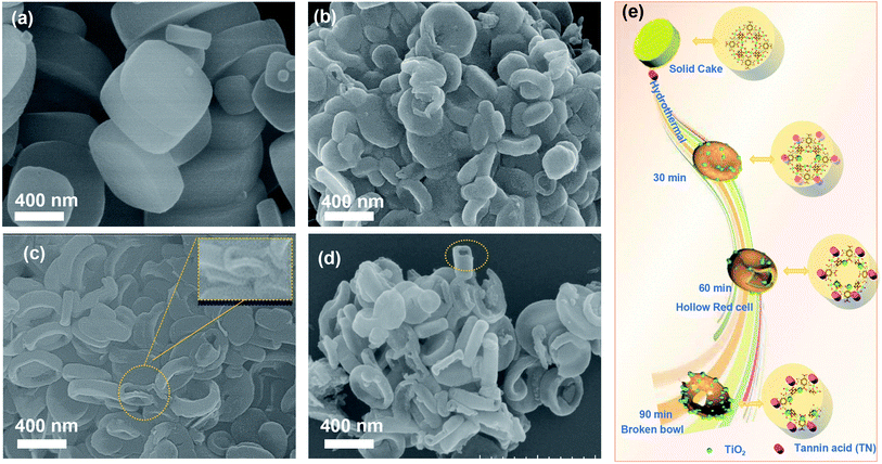 | ||
| Fig. 2 SEM images of (a) NH2-MIL-125, (b) HRBC-MOF-30, (c) HRBC-MOF-60, and (d) HRBC-MOF-90. (e) Schematic illustration of the process of HRBC-MOF-x. | ||
Scanning electron microscopy (SEM) images (Fig. 2b–d) clearly show that the microstructure of HRBC-MOF-x was decided by the hydrothermal reaction time. Moreover, the transformation from cakes to a hollow RBC-like structure was very rapid. After hydrothermal reaction for 30 min (Fig. 2b), there were almost no observed HRBC structures on NH2-MIL-125, and the product after reaction for 60 min (HRBC-MOF-60) contained almost all HRBC structures (Fig. 2c and inset of Fig. 2c). When the reaction time was extended to 90 min, the HRBC structures were generally destroyed (Fig. 2d), perhaps because the free protons released from the TN reacted with the surface of NH2-MIL-125. Remarkably, breakdown of the frame occurred during the hydrothermal process, which was unfavorable for the surface area of the final electrode materials. To confirm the protective effect of TN on NH2-MIL-125 during hydrolysis, material (NH2-MIL-125-60) prepared from NH2-MIL-125 without TN was also synthesized, and its microstructure was tested. The SEM image in Fig. S3† confirmed the particle structures of NH2-MIL-125-60, which indicated that TN preserved the outer framework of the MOFs from being etched.
The protective effect of TN on NH2-MIL-125 was further confirmed by Fourier transform infrared (FTIR) spectra (Fig. S2a†). For NH2-MIL-125, the peaks at 644, 1253, 1564, 1669, and 3325 cm−1 were regarded as the O–Ti–O stretching vibration, N–H in-plane bending vibration, C–N stretching vibration, C![[double bond, length as m-dash]](https://www.rsc.org/images/entities/char_e001.gif) O stretching of aromatic amine, and the N–H stretching vibration, respectively, which were in agreement with previous reports on NH2-MIL-125.21,22 As expected, there was very little change in the characteristic bands of NH2-MIL-125 after hydrolysis in the presence of TN (see the curves for HRBC-MOF-x). In comparison, the C
O stretching of aromatic amine, and the N–H stretching vibration, respectively, which were in agreement with previous reports on NH2-MIL-125.21,22 As expected, there was very little change in the characteristic bands of NH2-MIL-125 after hydrolysis in the presence of TN (see the curves for HRBC-MOF-x). In comparison, the C![[double bond, length as m-dash]](https://www.rsc.org/images/entities/char_e001.gif) O on HRBC-MOF-x at approximately 1705 cm−1 visibly increased. Moreover, the peaks of N–H on HRBC-MOF-x were not observed, demonstrating the bonding interaction between TN and amino functional groups of NH2-MIL-125. More importantly, without TN, characteristic bands disappear after hydrolysis, verifying the protection provided by TN for NH2-MIL-125. In addition, all peaks of NH2-MIL-125-60 were consistent with those of previously reported TiO2.23,24 In detail, the bands at 3420, 1620, 1300, and 718 cm−1 were vested in the O–H stretching, O–H bending, water adsorption, and Ti–O–Ti stretching vibrations, respectively. The FTIR spectroscopy results further demonstrated that TN plays a central role in the preparation of MOF-based self-templates with HRBC-like structures.
O on HRBC-MOF-x at approximately 1705 cm−1 visibly increased. Moreover, the peaks of N–H on HRBC-MOF-x were not observed, demonstrating the bonding interaction between TN and amino functional groups of NH2-MIL-125. More importantly, without TN, characteristic bands disappear after hydrolysis, verifying the protection provided by TN for NH2-MIL-125. In addition, all peaks of NH2-MIL-125-60 were consistent with those of previously reported TiO2.23,24 In detail, the bands at 3420, 1620, 1300, and 718 cm−1 were vested in the O–H stretching, O–H bending, water adsorption, and Ti–O–Ti stretching vibrations, respectively. The FTIR spectroscopy results further demonstrated that TN plays a central role in the preparation of MOF-based self-templates with HRBC-like structures.
X-ray diffraction (XRD) was employed to further confirm the existence of TN in HRBC-MOF-x (Fig. S2b†). The diffraction peaks at 24° were assigned to the TN component of HRBC-MOF-x, which was consistent with that of the FTIR analysis. In addition, the XRD pattern of HRBC-MOF-x exhibited diffraction peaks from NH2-MIL-125 and faintly from anatase, indicating that the HRBC-MOF-x was composed of NH2-MIL-125, TN, and TiO2. Longer hydrothermal reaction time led to additional TiO2.
On the basis of the above results, it can be concluded that hollow RBC-like structures were synthesized by a controlled selective protection process. Specifically, the inner part with high crystallization dissolves and forms TiO2 into a hollow cake structure due to the high surface energy at the shell. With the reaction time prolonged, imbalanced growth occurs, leading to a collapse of the hollow cake and the formation of a RBC-like nanoparticle (Fig. 2e).
2.2. Characterization of HRBC-NTO/N-C-x electrode materials
After pyrolysis and alkalization of these self-templates, HRBC-NTO/N-C-x (x = 0, 30, 60, and 90) variants were obtained (Fig. 3a–d and S3b†). Compared with numerous self-template counterparts, the morphology and average size of HRBC-NTO/N-C-0, HRBC-NTO/N-C-60, HRBC-NTO/N-C-90, and NTO-60 did not dramatically change, except that the surface coarsened. However, HRBC-NTO/N-C-30 (Fig. 3b) was significantly smaller than the initial HRBC-MOF-30 (Fig. 2b). This occurred because the large cavity of HRBC-MOF-30 was unable to resist the impact of gas produced by the annealing process, leading to size shrinkage of the materials. More significantly, it was easily found that HRBC-NTO/N-C-60 formed the hollow RBC-like structures in Fig. 3c and the inset of Fig. 3c. Materials with HRBC-like structures exhibit remarkable performances that differ from their hollow and solid spherical counterparts, with the advantages of effective ion transport paths. Therefore, HRBC-NTO/N-C-60 may exhibit outstanding desalination capability.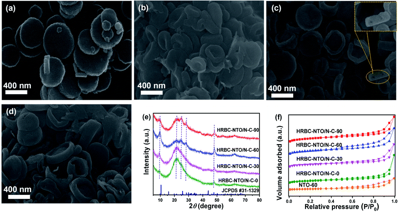 | ||
| Fig. 3 SEM images of (a) HRBC-NTO/N-C-0, (b) HRBC-NTO/N-C-30, (c) HRBC-NTO/N-C-60, and (d) HRBC-NTO/N-C-90. (e) XRD patterns of HRBC-NTO/N-C-x. (f) N2 sorption isotherms of HRBC-NTO/N-C-x and NTO-60. | ||
The microstructure of HRBC-NTO/N-C-60 was further ascertained by transmission electron microscopy (TEM) images (Fig. S4a†). We observed that Na2Ti3O7 nanoparticles (average diameters of approximately 4 nm) were well-dispersed in the carbon matrix (Fig. S4b†), which would serve to increase the charge transport and prevent agglomeration of Na2Ti3O7 nanoparticles. The high-resolution (HRTEM) images (Fig. S4c and d†) showed that the lattice fringes of 0.34 and 0.35 nm readily correspond to the (101) and (201) layers of Na2Ti3O7,25,26 respectively, indicating that the titanium component of HRBC-MOF-60 transformed into Na2Ti3O7. Thus, the prepared HRBC-NTO/N-C-60 with a unique HRBC architecture can integrate the features of 0D nanoparticles for direct charge transfer pathways and 3D hollow RBC-like structures for abundant active sites, which will enhance charge transport, induce interface polarization, and extend the active surface area.
The detailed crystal phase of HRBC-NTO/N-C-x was observed by XRD spectra. The diffraction peaks of HRBC-NTO/N-C-60 as well as HRBC-NTO/N-C-90 located at 9.7°, 25.1°, 28.1°, and 49.1° were assigned to the (100), (102), (111), and (303) crystalline planes of layered Na2Ti3O7 (JCPDS #31-1329) (Fig. 3e),27,28 respectively. This analysis was in accordance with the HRTEM results. Moreover, the diffraction peak at approximately 21° (Fig. 3e) indicated the existence of the components of carbon. This result also suggested that the Na2Ti3O7/N-C composite was prepared using the strategy of a MOF self-template. Moreover, the intensity of the peaks of Na2Ti3O7 in HRBC-NTO/N-C-0 and HRBC-NTO/N-C-30 were lower than those in HRBC-NTO/N-C-60 and HRBC-NTO/N-C-90, which indicated that bits of Na2Ti3O7 were contained in HRBC-NTO/N-C-0 and HRBC-NTO/N-C-30.
The surface area (SBET) and pore volume (Vpore) of materials play a central role in the electrochemical desalination performance of materials. Therefore, N2 adsorption–desorption measurements were conducted. A sharply increased trend at low pressure (P/P0 < 0.1) and a hysteresis loop appearing at the high pressure region (Fig. 3f) were observed, indicating that a porous feature exists in HRBC-NTO/N-C-x.29 The values of SBET and Vpore were fitted by the Brunauer–Emmett–Teller (BET) method (Table 1). The SBET and Vpore of NTO-60 (46.12 m2 g−1, 0.23 cm3 g−1) were lower than those of HRBC-NTO/N-C-x, indicating the importance of the selective protection of TN. In addition, the SBET and Vpore of HRBC-NTO/N-C-30 were much smaller than those of the other HRBC-NTO/N-C-x (x is unequal to 30), perhaps because of the annealing-induced shrinkage of HRBC-MOF-30 during the formation of HRBC-NTO/N-C-30. More importantly, the electrode of HRBC-NTO/N-C-60 exhibited a higher surface area (311.11 m2 g−1) and larger pore volume (0.61 cm3 g−1) compared to HRBC-NTO/N-C-0 (278.28 m2 g−1, 0.57 cm3 g−1) and HRBC-NTO/N-C-30 (160.44 m2 g−1, 0.50 cm3 g−1), as well as HRBC-NTO/N-C-90 (195.49 m2 g−1, 0.60 cm3 g−1), due to the superiority of the hollow RBC-like structure. Moreover, it is commonly accepted that a high surface area and pore volume will enhance the desalination performance of electrode materials.30 Thus, HRBC-NTO/N-C-60 with the highest surface area may have the greatest desalination capacity.
| Samples | BET surface area (m2 g−1) | Pore volume (cm3 g−1) |
|---|---|---|
| HRBC-NTO/N-C-0 | 278.28 | 0.57 |
| HRBC-NTO/N-C-30 | 160.44 | 0.50 |
| HRBC-NTO/N-C-60 | 311.11 | 0.61 |
| HRBC-NTO/N-C-90 | 195.49 | 0.60 |
| NTO-60 | 46.12 | 0.23 |
The X-ray photoelectron spectroscopy (XPS) survey spectrum of HRBC-NTO/N-C-60 (Fig. 4a) showed the presence of C, Ti, Na, N, and O elements. Elemental N appeared in the spectrum of HRBC-NTO/N-C-60, perhaps because the amino terephthalic acid of HRBC-MOF-60 can be used as a N source during the process of preparing HRBC-NTO/N-C-60. The N 1s spectrum of HRBC-NTO/N-C-60 can be divided into four peaks, which were attributed to pyridine-N (338.5 eV), pyrrolic-N (339.8 eV), oxidized-N (400.9 eV), and graphitic-N (403.1 eV) species (Fig. 4b).31,32 The results proved that N was introduced into the carbon skeletons.
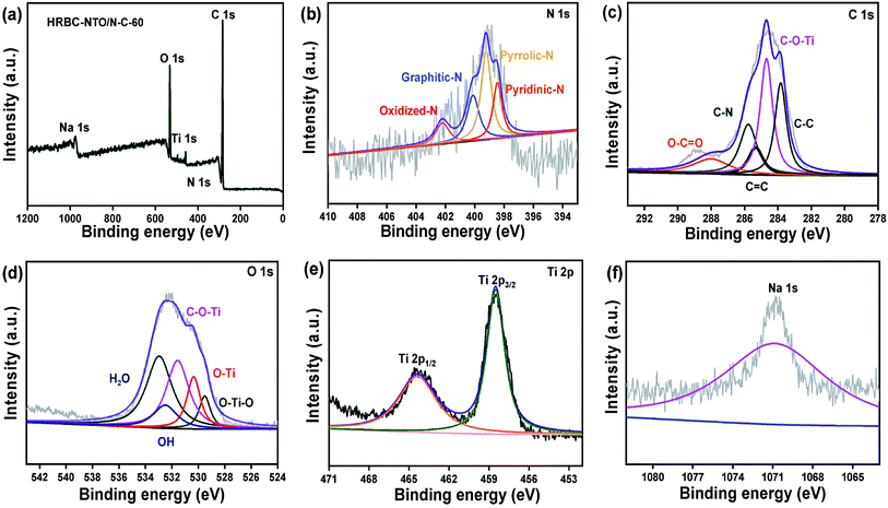 | ||
| Fig. 4 (a) XPS survey spectra and (b) N 1s, (c) C 1s, (d) O 1s, (e) Ti 2p, and (f) Na 1s high-resolution XPS spectra of HRBC-NTO/N-C-60. | ||
HRBC-NTO/N-C-60 can integrate the advantages of pyridine-N (pyrrolic-N) for rich cationic storage sites and graphitic-N for low electron transfer resistance,33 thereby further enhancing its desalination performance. For the C 1s spectrum (Fig. 4c), the peaks at 283.8, 284.8, 286.0, 286.5, and 287.9 eV were well matched with C–C, C–O–Ti, C–O, C![[double bond, length as m-dash]](https://www.rsc.org/images/entities/char_e001.gif) O, and C–N, respectively.34 Thus, the bond of C–N was observed, further confirming the existence of elemental N in materials. In addition, the appearance of C–O–Ti bonds clearly proved the existence of bonds between Na2Ti3O7 and nitrogen-rich carbon. It is commonly accepted that the formation of a chemical bond between Na2Ti3O7 and a carbon body supports electron transport. The high-resolution O 1s spectrum (Fig. 4d) further verified the presence of C–O–Ti bonds (531.1 eV). From Fig. 4d, four other types of O environments can be found in HRBC-NTO/N-C-60, including O–Ti–O (529.4 eV), O–Ti (530.5 eV), O–H (531.8 eV), and absorbed water (denoted as H2O, 532.9 eV).35,36 With regard to the Ti 2p XPS spectrum (Fig. 4e), the two peaks at 464.6 and 458.9 eV were derived from Ti 2p1/2 and Ti 2p3/2 of Ti4+ in HRBC-NTO/N-C-60, respectively.37 For the Na 1s XPS spectrum (Fig. 4f), the peak at 1071.6 eV was assigned to Na with a proton.
O, and C–N, respectively.34 Thus, the bond of C–N was observed, further confirming the existence of elemental N in materials. In addition, the appearance of C–O–Ti bonds clearly proved the existence of bonds between Na2Ti3O7 and nitrogen-rich carbon. It is commonly accepted that the formation of a chemical bond between Na2Ti3O7 and a carbon body supports electron transport. The high-resolution O 1s spectrum (Fig. 4d) further verified the presence of C–O–Ti bonds (531.1 eV). From Fig. 4d, four other types of O environments can be found in HRBC-NTO/N-C-60, including O–Ti–O (529.4 eV), O–Ti (530.5 eV), O–H (531.8 eV), and absorbed water (denoted as H2O, 532.9 eV).35,36 With regard to the Ti 2p XPS spectrum (Fig. 4e), the two peaks at 464.6 and 458.9 eV were derived from Ti 2p1/2 and Ti 2p3/2 of Ti4+ in HRBC-NTO/N-C-60, respectively.37 For the Na 1s XPS spectrum (Fig. 4f), the peak at 1071.6 eV was assigned to Na with a proton.
All of the above-mentioned SEM, XPS, XRD, and TEM results confirmed that the 0D–3D hierarchical Na2Ti3O7 nanoparticles were formed into a hollow N-doped porous carbon RBC-like architecture by a self-template strategy. The morphology and structure of Ag@rGO was discussed in detail in our previous study.38
2.3. Electrochemical performance
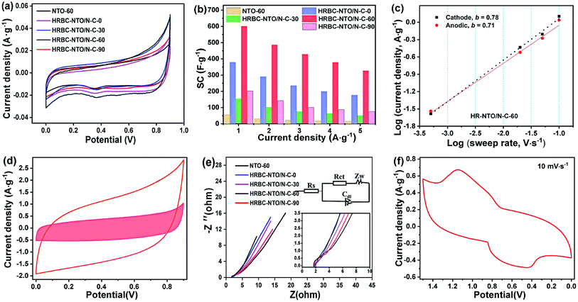
To gain additional insight into the electrochemical capability of HRBC-NTO/N-C-x and NTO-60 to store sodium ion, a series of electrochemical measurements were obtained in 2 mol L−1 NaCl electrolyte using a three-electrode system. Cyclic voltammetry (CV) curves of as-prepared cathode materials at 0.05 mV s−1 show that there are two peaks located at 0.3 V (reduction peak) and 0.7 V (oxidation peak), and they were attributed to Na+ insertion and extraction, respectively (Fig. 5a). The relevant reaction is depicted in the following formula:39| Na2Ti3O7 + xNa+ + xe− ↔ Na2 + xTi3O7 |
Compared with other materials, the HRBC-NTO/N-C-60 electrode showed a larger integrated area of CV curves, implying that HRBC-NTO/N-C-60 had the ability to store a higher quantity of sodium ion.40 The storage property can be estimated by specific capacitance (SC), which was approximated from the galvanostatic charge–discharge (GCD) curves. Fig. S5a–e† shows that the discharge time for the GCD curves of HRBC-NTO/N-C-60 was longer than that of other as-prepared cathode materials at every current density. Hence, the value of SC for HRBC-NTO/N-C-60 was much larger than that of HRBC-NTO/N-C-0, HRBC-NTO/N-C-30, HRBC-NTO/N-C-90, or NTO-60 (Fig. 5b), which was consistent with the CV analysis. The current response can be divided into two parts, which were assigned to the surface-controlled and diffusion-controlled Na+ insertion. According to previous reports, the power-law formula (i = avb) can be used to estimate the current contribution of an electrode,41 and i and v correspond to the current and scan rate, respectively. By determining the b values, the mechanisms of current response can be preliminarily determined. Specifically, b = 0.5 represents a diffusion-controlled process, and b = 1.0 indicates a surface capacitance controlled process. To clearly depict the current response of HRBC-NTO/N-C-60, we have conducted CV tests at different scan rates (v) (Fig. S5f†), and the plot (b) of the log(i)−log(v) line was calculated (Fig. 5c). Obviously, the electrochemical processes of HRBC-NTO/N-C-60 were dual-mode.42 These results can be confirmed using Trasatti's method, i = k1ν + k2ν1/2, thereinto, k1ν and k2ν1/2 were the capacitance contribution and diffusion-controlled contribution, respectively.43 The capacitance contribution was 8.59%, 19.67%, 25.69%, 33.65%, and 37.51% at the scan rate of 0.05, 2, 5, 10, and 20 mV s−1, respectively, for the HRBC-NTO/N-C-60 electrode (Fig. 5d and S6a†). These results further prove that the total capacitance was controlled by a dual mode, which was beneficial for obtaining a high desalination capacity and rate.34
We used electrochemical impedance spectroscopy (EIS) to attempt to determine the potential reasons for the occurrence of the outstanding specific capacitance (SC) of HRBC-NTO/N-C-60. Briefly, the Nyquist impedance plot can be considered as a combination of parts, namely the (semicircle) and low frequency (straight line). It is recognized that the charge transfer resistance (Rct) of electrode materials can be estimated from a semicircle. The semicircle of HRBC-NTO/N-C-60 was the smallest (Fig. 5e), suggesting that the lowest charge transfer resistance was from HRBC-NTO/N-C-60. Thus, this appreciable SC performance could be attributed to the hollow RBC-like structural features, improved charge-transfer characteristics, and high conductivity of HRBC-NTO/N-C-60, and all of these properties were significant for increasing the number of effective active sites.
In addition, the electrochemical performance of Ag@rGO was explored by CV test. As shown in Fig. S6b,† a pair of obvious redox peaks can be seen, indicating the intercalation/de-intercalation of Cl− that occurred within Ag@rGO.13 Thereafter, an asymmetrical supercapacitor was found using HRBC-NTO/N-C-60 and Ag@rGO. Fig. 5f shows two pairs of redox peaks, which denote the adsorption and desorption of amphoteric ion in brine solution, whose reactions can be proposed as the following chemical equation:
| Na2Ti3O7 + xNaCl + xAg ↔ Na2 + xTi3O7 + xAgCl |
It should be noted that water splitting does not obviously occur at the stated operating voltage range (−0.6 to 1.5 V) due to the inner resistance existing in the circuit. Thus, the maximum operating voltage for this desalination test can be set as 1.4 V.
2.4. Deionization performance
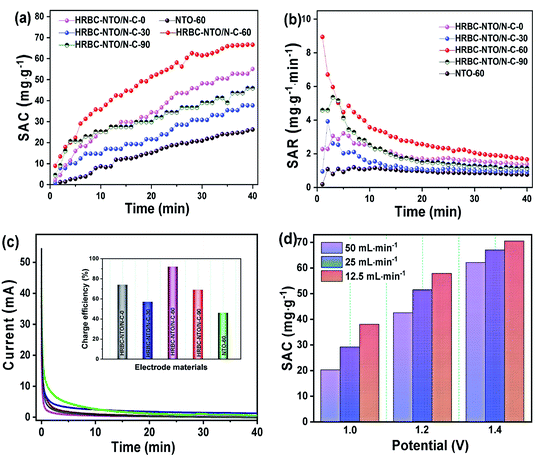
To probe the desalination property of NTO-60 and HRBC-NTO/N-C-x, a desalination battery device was constructed, with Na2Ti3O7-based materials as the cathode for Na+ capture and Ag@rGO as the anode for Cl− capture (Fig. S6c†), and it was estimated in 200 mg L−1 NaCl solution at 1.4 V with a flow rate of 25 mL min−1. The corresponding conductivity differentiations versus time curves are shown in Fig. S6d.† The conductivity of the HRBC-NTO/N-C-60 electrode was clearly lower than that of the other as-prepared materials, indicating the presence of abundant active sites in the electrode interior due to the favorable electron transport in the hollow RBC-like structures and the excellent electrical connection between the 0D Na2Ti3O7 nanoparticles and conductive 3D N-doped porous carbon matrixes.Desalination in terms of the value of the salt adsorption capacity (SAC) was quantized in terms of the relationship between solution conductivity (y, us cm−1) and concentration (x, mg L−1) of the NaCl solution (y = 86.74 + 1.85x) as well as eqn (S2†). As shown in Fig. 6a, a high SAC of 66.8 mg g−1 was measured for HRBC-NTO/N-C-60, which was much larger than those found for NTO-60, HRBC-NTO/N-C-0, HRBC-NTO/N-C-30, or HRBC-NTO/N-C-90, the values of which were 25.1, 54.2, 37.5, and 46.0 mg g−1, respectively. Moreover, HRBC-NTO/N-C-60 also exhibited a high salt absorption rate (SAR) of 8.9 mg g−1 min−1 (Fig. 6b), surpassing those of NTO-60 (1 mg g−1 min−1), HRBC-NTO/N-C-0 (5.4 mg g−1 min−1), HRBC-NTO/N-C-30 (3.2 mg g−1 min−1), and HRBC-NTO/N-C-90 (3.9 mg g−1 min−1).
Fig. 6c and the inset of Fig. 6c indicate that the charge efficiency of HRBC-NTO/N-C-60 (0.92) was higher than those of NTO-60 (0.46), HRBC-NTO/N-C-0 (0.74), HRBC-NTO/N-C-30 (0.57), and HRBC-NTO/N-C-90 (0.69). Those results confirmed that the preparation of materials with HRBC structures can improve the desalination performance of electrode materials. Surprisingly, the SAC and SAR of HRBC-NTO/N-C-60 was nearly 1.2 times as much as the reported materials (Table S1†), including C@NTO, rGO@NTO, MnO2, Co–Fe-LDH, MoS2, and so on. The ultra-desalination capacity of our HRBC-NTO/N-C-60 can be ascribed as follows: The unique novel hollow 3D RBC-like architecture of HRBC-NTO/N-C-60 increases the packing density of electrode materials and promotes access of the ions to the electrode. In addition, benefiting from the well-dispersed 0D Na2Ti3O7 nanoparticles, additional active sites were introduced onto the surface of the material, which can further facilitate ionic/electronic diffusion kinetics.
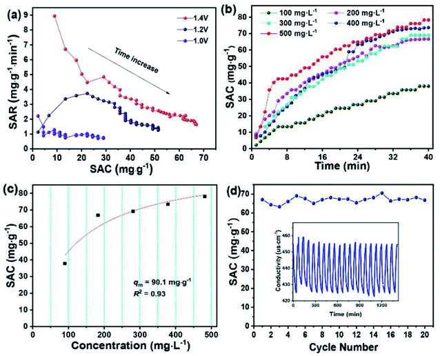
The desirable properties of HRBC-NTO/N-C-60 for desalination were further determined at different applied voltages and various flow rates (Fig. S7a–c†). Obviously, at 1.4 V, the maximum SAC of HRBC-NTO/N-C-60 was obtained regardless of the flow rate of the NaCl solution (Fig. 6d). A faster SAR at 1.4 V was also obtained, as shown in Fig. S8a† and 7a, which might have resulted because of the greater electrostatic interaction at a higher electrical pressure.7 Thus, at 1.4 V, the highest SAC and SAR was obtained for HRBC-NTO/N-C-60. Furthermore, the SAC for HRBC-NTO/N-C-60 in 200 mg L−1 NaCl solution at 1.4 V decreased from 70.5 and 66.8 to 60.3 as the flow rate increased from 12.5 and 25 to 50 mL min−1 (Fig. 6d), because the ions in solution were insufficient to contact the active sites of the electrode materials at a high flow rate.44 Distinctly, when the flow rate was 12.5 and 25 mL min−1, there was a minor difference in the deionization property of HRBC-NTO/N-C-60 (Fig. 6d and S8a†). Thus, the flux rate of 25 mL min−1 was adopted in follow-up studies.
For CDI practical applications, there are usually different concentrations in real-world sources of brine that require desalination.4 Thus, it was important to achieve high desalination performance over a range of concentrations. To this end, NaCl solutions with different initial concentrations in the range 100 to 500 mg L−1 were used to further study the deionization performance of HRBC-NTO/N-C-60. In Fig. S8b–f,† the conductivity of the solutions was decreased with the lengthening of the electro-adsorption time, which revealed that the salt ions in the solutions were removed. Moreover, the SAC values of HRBC-NTO/N-C-60 ranged from 37.9, 66.8, 69.1, and 73.4 to 78.1 mg g−1 as the concentrations increased from 100, 200, 300, and 400 to 500 mg L−1 (Fig. 7b), demonstrating its favorable potential for electrochemical applications involving high salinity feeds. Ulteriorly, the maximum desalination capacity (qm) of HRBC-NTO/N-C-60 was fitted by Langmuir isotherm:45
In the above equation, KL, q, and C represent a constant, SAC (mg g−1), and equilibrium concentration (mg L−1), respectively. The Langmuir curves of HRBC-NTO/N-C-60 are shown in Fig. 7c. The qm value for HRBC-NTO/N-C-60 was 90.1 mg g−1.
Finally, the reusability of HRBC-NTO/N-C-60 was also investigated in a 200 mg L−1 NaCl solution at 1.4 V with a flow rate of 25 mL min−1. As shown in Fig. 7d, the HRBC-NTO/N-C-60-based desalination system displays an outstanding cycling stability with only 5% desalination capacity degradation over 20 cycles, which indicated the favorable reusability of HRBC-NTO/N-C-60. The superior long-term stability can be ascribed to its unique composite structure that can enhance stability during the repeated intercalation and deintercalation process. Notably, the 5% desalination capacity reduction after 20 cycles could be mainly due to two factors: (i) The repeated intercalation and deintercalation of Na+ during the desalination process could cause some slight morphology change in HRBC-NTO/N-C-60 (Fig. S9a†), which will degrade the performance of the desalination system; (ii) Fig. S9† shows that most of the electrode materials remain intact, but mild agglomeration of Ag occurs during the multi-cycle desalination test, which may cause a reduction in the desalination capacity.
3. Conclusions
We successfully synthesized NH2-MIL-125-based hollow red blood cells (HRBC-MOF-60) by simply reacting cake-like NH2-MIL-125 with TN. An interesting selective protection mechanism was revealed to account for the fabrication of hollow RBC-like structures. After annealing and controlled hydrothermal reaction, HRBC-MOF-60 was transformed into a Na2Ti3O7/N-doped porous carbon composite with hollow RBC-like structures (HRBC-NTO/N-C-60). The anchor of 0D Na2Ti3O7 nanoparticles into N-doped porous carbon with a unique hollow RBC-like structure provides the composite with abundant effective active sites, modified electron transport, and accelerated charge/mass transfer ability as well as weakened agglomeration, thereby enhancing the storage performance of sodium ions. Therefore, when evaluated as an electrode material for a desalination battery, HRBC-NTO/N-C-60 exhibited enhanced desalination properties (66.8 mg g−1) compared with solid materials. The present success not only indicates the ability to create hollow structures using a self-template method for MOFs, but it also provides a new method for facile preparation of materials with hollow structures for diverse applications.Data availability
The data that support the findings of this study are available in the article and its ESI,† or from the corresponding authors on reasonable request.Author contributions
Yingying Zhang: conceptualization, data curation, methodology, software, writing – original draft. Xiaogeng Feng: reviewed and edited the manuscript. Yuejiao Wang: data curation. Weijun Shan: data curation, Visualization. Zhenning Lou: conceptualization. Ying Xiong: conceptualization, funding acquisition, supervision, writing – review and editing. All persons who have made a substantial contribution to the work have been reported in the manuscript.Conflicts of interest
There are no conflicts to declare.Acknowledgements
This project is supported by the National Natural Science Foundation of China (51674131, 21373005, 51902149, 22006062), Natural Science Foundation of Liaoning Province of China (2021-MS-154, 2019-MS-156, RC190346), the LiaoNing Revitalization Talents Program (XLYC1907197), the Liaoning BaiQianWan Talents Program (LBTP2019025), and the Liaoning Innovative Research Team in University (LDGY2019009, LT2019006).References
- Z. B. Ding, X. X. Tao, J. B. Li, Y. Q. Li, K. Wang, T. Lu, M. S. A. Hossain, M. A. Amin, S. H. Zhang, L. K. Pan and Y. Yamauchi, Chem. Eng. J., 2022, 430, 133161–133168 CrossRef CAS.
- D. H. Nam, M. A. Lumley and K. S. Choi, ACS Energy Lett., 2021, 6, 1034–1044 CrossRef CAS.
- Z. Q. Chen, X. T. Xu, Z. B. Ding, K. Wang, X. Sun, T. Lu, M. Konarova, M. Eguchi, J. G. Shapter, L. K. Pan and Y. Yamauchi, Chem. Eng. J., 2021, 407, 127148–127156 CrossRef CAS.
- Q. Li, X. T. Xu, J. R. Guo, J. P. Hill, H. S. Xu, L. X. Xiang, C. Li, Y. Yamauchi and Y. Y. Mai, Angew. Chem., Int. Ed., 2021, 60, 26528–26534 CrossRef CAS PubMed.
- S. Dutta, S. Y. Huang, C. Chen, J. E. Chen, Z. A. Alothman, Y. Yamauchi, C. H. Hou and K. C. W. Wu, ACS Sustainable Chem. Eng., 2016, 4, 1885–1893 CrossRef CAS.
- W. H. Shi, X. T. Qian, M. B. Xue, W. B. Que, X. L. Gao, D. Zheng, W. X. Liu, F. F. Wu, J. N. Shen, X. H. Cao and C. J. Gao, ACS Appl. Mater. Interfaces, 2021, 13, 21149–21156 CrossRef CAS PubMed.
- K. Wang, Y. Liu, Z. B. Ding, Z. Q. Chen, X. X. Tao, M. Wang, T. Lu and L. K. Pan, Chem. Eng. J., 2022, 433, 133578–133588 CrossRef CAS.
- K. Wang, Y. Liu, Z. B. Ding, Z. Q. Chen, G. Zhu, X. T. Xu, T. Lu and L. K. Pan, Sep. Purif. Technol., 2022, 278, 119565–119576 CrossRef CAS.
- S. Y. Wang, G. Wang, X. Che, S. Wang, C. Li, D. Li, Y. Zhang, Q. Dong and J. Qiu, Environ. Sci.: Nano, 2019, 6, 2379–2388 RSC.
- F. Zhou, T. Gao, M. Luo and H. B. Li, Chem. Eng. J., 2018, 343, 8–15 CrossRef CAS.
- Z. Yue, T. Gao and H. Li, Desalination, 2019, 449, 69–77 CrossRef CAS.
- C. L. Li, O. Dag, T. D. Dao, T. Nagao, Y. Sakamoto, T. Kimura, O. Terasaki and Y. Yamauchi, Nat. Commun., 2015, 6, 6608–6616 CrossRef CAS PubMed.
- C. L. Li, M. Iqbal, B. Jiang, J. Kim, A. K. Nanjundan, A. E. Whitten, K. Wood and Y. Yamauchi, Chem. Sci., 2019, 10, 4054–4061 RSC.
- J. Liang, X. Y. Yu, H. Zhou, H. B. Wu, S. J. Ding and X. W. Lou, Angew. Chem., Int. Ed., 2014, 126, 13017–13021 CrossRef.
- J. Liang, H. Kou and S. J. Ding, Adv. Funct. Mater., 2021, 31, 2007801–2007822 CrossRef CAS.
- S. Chen, Y. C. Pang, J. Liang and S. J. Ding, J. Mater. Chem. A, 2018, 6, 13164–13170 RSC.
- J. Feng and Y. Yin, Adv. Mater., 2019, 31, 1802349–1802363 CrossRef PubMed.
- M. Wang, X. T. Xu, J. Tang, S. J. Hou, M. S. A. Hossain, L. K. Pan and Y. Yamauchi, Chem. Commun., 2017, 53, 10784–10787 RSC.
- Y. J. Li, Y. Liu, M. Wang, X. T. Xu, T. Lu, C. Q. Sun and L. K. Pan, Carbon, 2018, 130, 377–383 CrossRef CAS.
- X. F. Lu, B. Y. Xia, S. Q. Zang and X. W. Lou, Angew. Chem., Int. Ed., 2020, 59, 4634–4650 CrossRef CAS PubMed.
- Q. Q. Huang, Y. Hu, Y. Pei, J. H. Zhang and M. L. Fu, Appl. Catal., B, 2019, 259, 118106–118120 CrossRef CAS.
- G. L. Mo, L. X. Wang and J. H. Luo, Sep. Purif. Technol., 2021, 277, 119643–119655 CrossRef CAS.
- M. Y. Chi, X. N. Sun, G. Lozano-Blanco and B. J. Tatarchuk, Appl. Surf. Sci., 2021, 570, 151147–151159 CrossRef CAS.
- L. B. Bi, Z. L. Chen, L. H. Li, J. Kang, S. X. Zhao, B. Y. Wang, P. W. Yan, Y. B. Li, X. X. Zhang and J. M. Shen, J. Hazard. Mater., 2021, 407, 124759–124771 CrossRef CAS PubMed.
- S. Dong, Z. Li, I. A. Rodríguez-Pérez, H. Jiang, J. Lu, X. Zhang and X. Ji, Nano Energy, 2017, 40, 233–239 CrossRef CAS.
- C. Ding, T. Nohira and R. Hagiwara, J. Power Sources, 2017, 354, 10–15 CrossRef CAS.
- X. Qiu, X. Zhang and L. Z. Fan, J. Mater. Chem. A, 2018, 6, 16186–16195 RSC.
- I. M. Iani, V. Teodoro, N. L. Marana, U. Coleto, J. R. Sambrano, A. Z. Simoes, M. D. Teodoro, E. Longo, L. A. Perazolli, R. A. C. Amoresi and M. Aparecida Zaghete, Appl. Surf. Sci., 2021, 538, 148137–148150 CrossRef CAS.
- X. T. Xu, H. Tang, M. Wang, Y. Liu, Y. Li, T. Lu and L. K. Pan, J. Mater. Chem. A, 2016, 4, 16094–16100 RSC.
- J. Guo, X. Xu, J. P. Hill, L. Wang, J. Dang, Y. Kang, Y. Li, W. Guan and Y. Yamauchi, Chem. Sci., 2021, 12, 10334–10340 RSC.
- X. Hu, X. Sun, S. J. Yoo, B. Evanko, F. Fan, S. Cai, C. Zheng, W. Hu and G. D. Stucky, Nano Energy, 2019, 56, 828–839 CrossRef CAS.
- J. Zhang, T. T. Yan, J. Fang, J. Shen, L. Y. Shi and D. S. Zhang, Environ. Sci.: Nano, 2020, 7, 926–937 RSC.
- Y. H. Tang, X. X. Wang, J. J. Chen, D. J. Wang and Z. Y. Mao, Chem. Eng. J., 2022, 427, 131951–131961 CrossRef CAS.
- K. Wang, Y. Liu, Z. B. Ding, Z. Q. Chen, G. Zhu, X. T. Xu, T. Lu and L. K. Pan, Sep. Purif. Technol., 2021, 278, 119565–119576 CrossRef.
- S. Y. Wang, Z. L. Li, G. Wang, Y. W. Wang, Z. Ling and C. P. Li, ACS Nano, 2022, 16, 1239–1249 CrossRef CAS PubMed.
- K. Wang, L. Chen, G. Zhu, X. T. Xu, L. J. Wan, T. Lu and L. K. Pan, Desalination, 2022, 522, 115420–115429 CrossRef CAS.
- L. Huang, T. T. Yan, A. E. D. Mahmoud, S. Li, J. Zhang, L. Y. Shi and D. S. Zhang, Environ. Sci.: Nano, 2021, 8, 950–959 RSC.
- Y. Y. Zhang, K. Yang, H. Yu, W. Shan, Z. Lou and Y. Xiong, J. Mater. Chem. A, 2021, 9, 24374–24386 RSC.
- W. Wang, C. Yu, Y. Liu, J. Hou, H. Zhu and S. Jiao, RSC Adv., 2013, 3, 1041–1044 RSC.
- H. Zhang, C. Wang, W. Zhang, M. Zhang, J. Qi, J. Qian, X. Sun, B. Yuliarto, J. Na, T. Park, H. G. A. Gomaa, Y. V. Kaneti, J. W. Yi, Y. Yamauchi and J. Li, J. Mater. Chem. A, 2021, 9, 12807–12817 RSC.
- B. S. Li, B. J. Xi, F. Wu, H. Z. Mao, J. Liu, J. K. Feng and S. L. Xiong, Adv. Energy Mater., 2019, 9, 1803070–1803079 CrossRef.
- S. Huo, P. Zhang, M. He, W. Zhang, B. Liang, M. Zhang, H. Wang and K. Li, Green Chem., 2021, 23, 8554–8565 RSC.
- X. H. Liu, S. H. Zhang, G. L. Feng, Z. G. Wu, D. Wang, M. D. Albaqami, B. H. Zhong, Y. X. Chen, X. D. Guo, X. T. Xu and Y. Yamauchi, Chem. Mater., 2021, 33, 1657–1666 CrossRef CAS.
- Z. Li, S. Mao, Y. Yang, Z. Sun and R. Zhao, J. Colloid Interface Sci., 2021, 585, 85–94 CrossRef CAS PubMed.
- X. Gong, W. Luo, N. Guo, S. Zhang, L. Wang, D. Jia, L. Ai and S. Feng, J. Mater. Chem. A, 2021, 9, 18604–18613 RSC.
Footnote |
| † Electronic supplementary information (ESI) available. See DOI: 10.1039/d1sc06476b |
| This journal is © The Royal Society of Chemistry 2022 |

![[thin space (1/6-em)]](https://www.rsc.org/images/entities/char_2009.gif)
