Single-phase Ni5P4–copper foam superhydrophilic and aerophobic core–shell nanostructures for efficient hydrogen evolution reaction†
Manisha
Das
,
Nityasagar
Jena
,
Taniya
Purkait
,
Navpreet
Kamboj
,
Abir
De Sarkar
and
Ramendra Sundar
Dey
 *
*
Institute of Nano Science and Technology (INST), Mohali-160064, Punjab, India. E-mail: rsdey@inst.ac.in
First published on 2nd August 2019
Abstract
The facile synthesis of a highly durable, low-cost and robust electrocatalyst for hydrogen generation from water is vital to address the existing environmental issues, as well as to provide an environmentally-friendly clean and green energy supply. Electrochemical deposition of single-phase nickel phosphide on galvanostatically deposited copper foam (Cuf@Ni5P4) core–shell nanostructure offers an innovation in the structural design of a new platform for novel electrocatalysts. The Cuf@Ni5P4 provides a superior three-dimensional conductive channel for ion transport during the catalytic process. The catalyst exhibits an excellent electrocatalytic activity towards the hydrogen evolution reaction (HER) in acidic media. The superhydrophilic and aerophobic properties of the porous electrode help the H2 gas bubbles to quickly leave the surface. Interestingly, it requires a very low overpotential of 90 mV for HER at a current density of 10 mA cm−2. The very small Tafel slope of 49 mV dec−1 and the very high exchange current density (∼0.76 mA cm−2) originate from the large electrochemically active surface area and the fast mass and electron transfer efficiency of the Cuf@Ni5P4 catalyst. A theoretical study was performed to investigate the mechanism underlying the HER activity in Cu-supported Ni5P4 at an atomic scale. Density functional theory (DFT) calculations suggest a very high negative Gibbs free energy change (ΔGH*) in Ni5P4 (0001)/Cu (111) upon hydrogen adsorption, which is actually responsible for the excellent HER activity of the catalyst. Furthermore, it shows remarkable durability for hydrogen generation under low (10 mA cm−2) and high current densities (160 mA cm−2) for >84 h with ∼96% retention of the overpotential, establishing a low-cost and efficient catalyst for sustainable, future energy generation strategies.
Introduction
The electrochemical generation of H2 from water has attracted considerable attention, as it is one of the promising approaches used for the production of renewable fuels aimed at future energy supply. Hydrogen generation is economically favorable and environmentally friendly as it generally gives pure products, which are free from CO.1,2 In addition, not only is H2 required as the starting material for fuel cells, several industries also have a demand for it as a precursor material for the production of ammonia and the refining of petroleum. To date, several catalysts for the hydrogen evolution reaction (HER) have been developed, among them, noble metal catalysts such as platinum for HER are recognized as benchmark catalysts owing to their high efficiency and low overpotential towards electrocatalytic reactions.2,3 However, due to limited resources and the expense of noble metal catalysts, transition metal (Ni, Co, Fe and Mn)-based catalysts have drawn attention owing to their performance and their abundant sources.Transition metal sulfides, phosphides and selenides are the most studied catalysts and have drawn enormous attention in recent years.4 Typically phosphorous-based transition metal pnictide with the earth abundant element nickel, and nickel phosphides have gained considerable attention as HER catalysts owing to their high activity and stability.5–8 Nickel phosphide exists in several phases in nanostructures such as Ni3P, Ni2P, Ni5P2, Ni5P4, NiP2 and Ni12P5.9 Ni2P was theoretically predicted to be an efficient HER electrocatalyst, even better than Pt,10 and experimental validation has been carried out by several researchers.1,11–15 Recently, Ni5P4 crystalline nanoparticles have been explored to produce H2 in acidic media.6,16,17 Although most of the mixed phased nickel phosphides are reported to have a good electrocatalytic activity towards HER, they also have some disadvantages such as uncontrolled agglomeration, less hydrophilicity and poor contact resistance which stop them from being used in commercial applications.18 Single-phase Ni5P4 has been proven to show better electrode kinetics than the multiphase nickel phosphides during catalysis. Pan et al. successfully synthesized single phase NiP2, Ni12P5 and Ni5P4, and showed that the single phase Ni5P4 was the best electrode material in terms of the HER among the other nickel phosphide based catalysts.5 This is owed to the amount of positive charge on the Ni (Niδ+) in Ni5P4, which is greater than the other nickel phosphides, this helps to achieve better catalytic performances. However, the synthesis of single-phase Ni5P4 is still a challenge to researchers in this field.
Strategic synthetic approaches and stepwise routes have been employed to create rational active sites to achieve the superior catalytic activity of nickel phosphide.13 Several procedures have recently been explored such as hydrothermal, high temperature reactions and wet chemical routes/hydrothermal in combination with a high temperature reaction and an electrochemical method for the synthesis of nanostructured nickel phosphide catalysts.4 However, to the best of our knowledge, to date an electrochemical synthesis of a single-phase nickel phosphide has not been reported, for instance crystalline Ni5P4, for the HER. Electrochemical synthesis has several advantages over other methods, such as: (i) the electrochemical reaction is usually a one-step process; (ii) it does not involve a high temperature for the phosphorization reaction; (iii) the reaction time is reduced; and (iv) self-supported catalyst loading is possible on the electrode surface. It has been established that a rough electrode surface is known to favor the electrodeposition of the desired material.19 Furthermore, an electrodeposited core–shell material offers a synergistic effect between the core and shell that results in the high efficiency of the nanostructures.20,21 Electrodeposited porous architectures have the advantages of creating a hydrophilic as well as a aerophobic surface, which helps to decrease the ohmic resistance of the electrode with electrolyte and the fast removal of gas bubbles from the surface.22 Herein, taking advantage of these effects, for the first time, we have explored the single-phase electrochemical synthesis of nickel phosphide (Ni5P4) on a galvanostatically deposited copper foam (Cuf) electrode. The dendritic nanostructure of Cuf offers a rough surface and acts as template for the deposition of Ni5P4. The core–shell morphology of Cuf@Ni5P4 further shows an excellent catalytic activity towards the HER in acidic medium.
Experimental
Preparation of copper foam electrode
The Cuf thin film was grown on Cu foil using the galvanostatic electrodeposition method following our previous report with a few modifications.23 First, a copper foil (0.5 × 0.5 cm2) was cleaned with dilute nitric acid followed by deionized (DI) water repeatedly and finally with ethanol. The Cu foil was kept in an argon atmosphere when not in use to avoid atmospheric oxidation. The deposition of Cuf was carried out using a two-electrode deposition process, in which the copper foil was used as both the cathode and anode with a fixed distance of 1.5 cm. A constant current density of 1 A cm−2 was applied between the electrodes placed in an electrochemical cell containing 0.4 M CuSO4 in 1.5 M H2SO4 for a duration of 45 s. The as-deposited Cuf was washed in DI water 3–4 times to remove any acidic residue and kept in an argon atmosphere for further use.Electrodeposition of Ni5P4 on copper foam
Electrodeposition of Ni5P4 on the Cuf was carried out under a constant potential of −0.8 V in a three-electrode system. Typically, electrodeposition was carried out in an aqueous solution of NiCl2·6H2O (60 mM), NaH2PO2·H2O (50 mM), and NaH2PO4 (0.5 M) for different periods of time (30, 60, 90 and 120 min). Previously deposited Cuf was used as a working electrode, platinum wire as the counter electrode, and Ag/AgCl (3 M KCl) as the reference electrode for all of the depositions. The as-deposited black layer of nickel phosphide (Fig. S1†) on Cuf thin film was washed thoroughly with Millipore water and stored under a vacuum when not in use.Electrode fabrication with Pt/C
A glassy carbon (GC) (2 mm diameter) electrode was cleaned with alumina powder as mentioned earlier for the preparation of Pt/C. Homogeneous ink was prepared using commercially available Pt/C (20 wt%) and was dispersed in a mixed solution of water and ethanol (1![[thin space (1/6-em)]](https://www.rsc.org/images/entities/char_2009.gif) :
:![[thin space (1/6-em)]](https://www.rsc.org/images/entities/char_2009.gif) 1, v/v) and followed by sonication for 30 min. The ink was further drop casted onto the GC electrode for Pt/C to obtain a mass loading of 0.5 mg cm−2.
1, v/v) and followed by sonication for 30 min. The ink was further drop casted onto the GC electrode for Pt/C to obtain a mass loading of 0.5 mg cm−2.
Electrochemical measurements
All of the electrochemical characterization measurements for the HER were conducted at room temperature (25 °C) with Cuf@Ni5P4 (0.5 × 0.5 cm2) as the working electrode, Ag/AgCl (3 M KCl) and the graphite rod were used as the reference and counter electrode, respectively. All of the linear sweep voltammetry (LSV) and cyclic voltammetry (CV) experiments were carried out to check the HER activity with 0.5 M H2SO4 as the electrolyte. All of the potentials used in this study were calibrated to a reversible hydrogen electrode (RHE) based on the formula| ERHE = (EAg/AgCl(3 M KCl) + 0.210 + 0.0591 pH)V |
The chronopotentiometric (CP) measurements were conducted to evaluate the durability of the as-prepared electrocatalyst under the same experimental conditions without compensating the iR drop. Commercial Pt/C catalysts were employed for hydrogen evolution, respectively, as the baseline catalysts for comparison. Electrochemical impedance spectroscopy (EIS) measurements were carried out at a potential of −0.2 V (vs. RHE) in the frequency range of 105–10−2 Hz. The polarization curves for all of the catalysts were iR corrected (unless mentioned otherwise) to minimize the effect of the ohmic resistance present at the electrode electrolyte interface and the current was normalized with the geometrical surface area. The iR-correction was performed according to the following equation:
| Ecorr = Emea − iRs |
Computational methodology
Density functional theory (DFT) calculations were performed within the Vienna ab initio simulation package (VASP).24 The ion-electron exchange correlation functionals were treated with the projector augmented wave (PAW)25,26 pseudopotentials by considering the Perdew–Burke–Ernzerhof (PBE)27 parametrization form of the generalized gradient approximation (GGA) with a kinetic energy cutoff of 500 eV to expand the electronic wave functions in a plane wave basis-set. A Γ-centered 5 × 5 × 1 k – mesh was used for the Brillouin zone (BZ) sampling with an energy threshold of 1 × 10⁻⁵ eV for the total energy convergence and a force tolerance of 0.01 eV Å−1 for the ionic and electronic relaxation. The periodic replicas of the slab geometry were decoupled by considering a large vacuum spacing of more than 20 Å along the z-axis. In addition, the van der Waals (vdW) corrections to the dispersive forces were explicitly treated using the Grimme DFT-D2 method for the surface adsorbed geometries.Results and discussion
Characterization of the electrode materials
The core–shell Cuf@Ni5P4 thin film electrode (Fig. S1, ESI†) was synthesized by the electrodeposition method in a three-electrode system at a constant potential of −0.8 V, which is schematically shown in Fig. 1 (details are given in the experimental section). The growth of Ni5P4 at different deposition times (30, 60, 90 and 120 min) was performed with the aim of achieving the best electrocatalytic activity of Cuf@Ni5P4 and the optimized time was found to be 90 min. All of the characterizations were conducted using Cuf@Ni5P4 prepared under the optimal conditions (i.e. a deposition time of 90 min). The structural analysis was investigated using X-ray powder diffraction (XRD) analysis. Fig. 2a and b displays the XRD pattern of Cuf@Ni5P4, in which all of the diffraction peaks are in good agreement with the hexagonal structure of Ni5P4 (JCPDS PDF 01-089-2588). The diffraction peaks at the 2θ values of 28.69°, 32.57°, 36.06°, 41.42°, 47.06°, 47.84°, 52.96°, 53.98°, 57.74°, 61.06°, 69.66°, 76.46° and 79.01° were attributed to the planes of (103), (004), (104), (211), (300), (301), (214), (220), (304), (107), (320), (226) and (413), respectively for Ni5P4. However, the diffraction peaks for bare Cuf at a 2θ of 43.19°, 50.30° and 73.89° correspond to the (111), (200) and (220) planes, respectively, for the cubic lattice (JCPDS PDF 01-070-3038), which were also observed as expected in the diffraction pattern of Cuf@ Ni5P4. However, the peaks of Cuf@Ni5P4 were observed to be shifted by an angle of approximately 0.3° with respect to the peak for bare Cuf towards a lower angle of 2θ owing to the uniform interfacial strain induced in the geometry of the core and shell which originated from the strong size mismatch between them.28,29 This confirms the interfacial interaction of the hybrid core–shell nanostructure formed during electrochemical synthesis.30 The two small peaks are observed at a 2θ of 37.24° and 38.95°, which corresponds to the (111) plane of NiO (PDF 00-047-1049) and the (111) plane of CuO (PDF 00-001-1117), respectively. The peak arising for CuO may be due to the exposure of the sample to the air atmosphere and the appearance of a small oxide peak of nickel (NiO) may be due to its formation in the working electrolyte conditions during the electrodeposition process.31,32 The selected area electron diffraction (SAED) pattern obtained during the transmission electron microscopic (TEM) measurement (Fig. 2c), again reveals the single-phase Ni5P4 formation on Cuf, which is well correlated with the XRD pattern.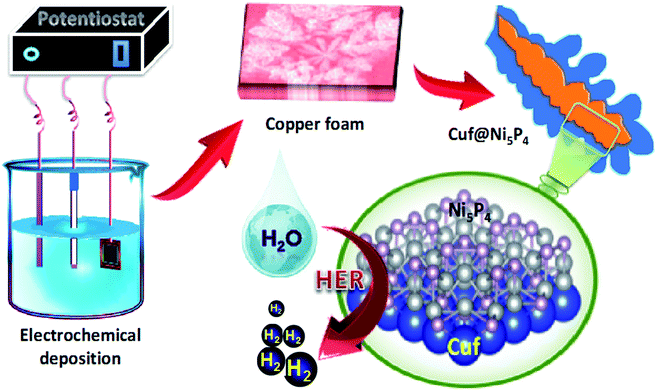 | ||
| Fig. 1 Schematic illustration of the electrochemical synthesis of the copper foam-nickel phosphide active material and the HER activity. | ||
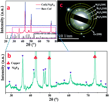 | ||
| Fig. 2 (a) XRD pattern for Cuf (blue) and Cuf@Ni5P4 (red); (b) scaled image of XRD of Cuf@Ni5P4; and (c) SAED pattern for Cuf@Ni5P4. | ||
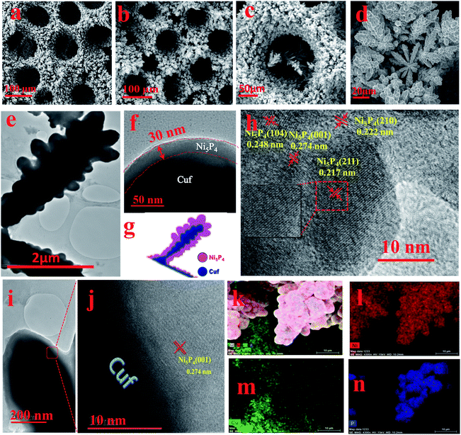
The surface morphological information for the as-deposited Cuf and Cuf@Ni5P4 was systematically investigated using scanning electron microscopy (SEM) and TEM. The SEM images of Cuf (Fig. 3a and S2, ESI†) show the honeycomb porous structure resulting from the generation and dissipation of H2 bubbles during the electrodeposition process.33 The SEM images of Cuf@Ni5P4 at different deposition durations demonstrate the growth of Ni5P4 with time (Fig. S3, ESI†). Cuf@Ni5P4 shows a similar structure to Cuf with uniformly distributed continuous macropores across the surface (Fig. 3b and S4, ESI†). Unlike Cuf@Ni5P4, the SEM images of the electrodeposited Ni5P4/GP, Ni5P4/Cu foil and the Ni5P4/Nif samples are particulate in nature (Fig. S5, ESI†). Although they have different morphologies, all of the materials exhibit aggregated particles throughout the surface. The pore size distribution (Fig. S6, ESI†) reveals that the average pore size of the bare Cuf was approximately 110 μm, which was reduced to an average pore size of approximately 85 μm in the Cuf@Ni5P4, which indicates the deposition of Ni5P4 is via the electrodeposition technique. The high-resolution SEM images at different magnifications, (Fig. 3c and d) further suggests the formation of a dendritic Ni5P4 film onto the copper foam.
The TEM images of the Cuf@Ni5P4 (Fig. 3e and S7a and b, ESI†) show the dendritic structure of the material. A close look at Fig. 3e and f shows the different intensities of the layer, which arise from the transmission dependency of the different atomic layers as schematically represented in Fig. 3g. The thickness of the deposited layer calculated from the high-resolution TEM (HRTEM) image was 30–40 nm (Fig. 3f) with a core diameter of 0.4–0.8 μm which proves the formation of a core shell nanostructure with copper as the core and Ni5P4 as the shell. This hierarchically structured electrode with a core–shell configuration is known to show excellent electrocatalytic activity towards hydrogen generation.21 The HRTEM study was performed with the Ni5P4 material as the shell (Fig. 3h). Well-resolved lattice fringes were observed with d-spacing values of 0.222, 0.248 and 0.217 nm, which correspond to the (210), (104) and (211) planes of Ni5P4, respectively. The junction of the core–shell heterostructures, as revealed from the HRTEM images shown in Fig. 3i and j, indicate the presence of the (001) plane of Ni5P4, grown on the copper (111) plane. The energy dispersive X-ray spectra (EDX) suggests the presence of Ni, Cu and P elements in the sample (Fig. S8, ESI†). The EDX mapping study was accomplished over a branched structure of Cuf@Ni5P4 (Fig. 3k–n). The EDX elemental mapping study proves the homogeneous distribution of the nickel, phosphorous and copper elements on the branched structure. It is noteworthy from the mapping analysis that the more intense red (for Ni) and blue (for P) color at the branched structure and the green color (for Cu) throughout the scanned area further confirm that the Ni5P4 thin film fully covered the Cuf nanostructure. The surface area, pore volume and pore size were analysed using the Brunauer–Emmett–Teller (BET) method using N2 adsorption–desorption isotherms (Fig. S9a, ESI†). The specific surface area of our material, Cuf@Ni5P4, was found to be 6.944 m2 g−1. The isotherms were type IV, which are usually identified for mesoporous materials. The average pore size was found to be 9.29 nm (Fig. S9b, ESI†), which plays a part in the efficient catalytic activity of the catalyst.
X-ray photoelectron spectroscopy (XPS) is an important tool to ascertain the chemical states of the elements present in a sample. As shown in Fig. 4a, the XPS survey scan confirms the presence of Ni, Cu, P, C as well as O elements. The presence of C and O can be attributed to the surface adsorbed electrolyte ion or surface oxidation of the material.11 The high-resolution XPS spectra of Ni 2P were employed to detect the metallic and oxidized peak corresponding to Ni 2P3/2 and Ni 2p1/2 (Fig. 4b). Interestingly, two metallic peaks for Ni (Niδ+) corresponding to 853.4 and 870.3 eV were identified.34,35 The spectrum of Ni 2P also indicates the presence of peaks at 856.8 (oxidized Ni) and 862.3 eV (satellite) for Ni 2p3/2 and at 875.6 (oxidized Ni) and 880.2 eV (satellite) for the Ni 2p1/2 energy level.5 The high-resolution spectrum of P 2p for the Cuf@Ni5P4, in which the peak at 129.9 eV was assigned to the P 2p3/2 and P 2p1/2, whereas the peak at 133.4 eV was attributed to the oxidized P species (Fig. 4c). The XPS spectra of copper present as a core in Cuf@Ni5P4 (Fig. 4d), indicates three main peaks at 932.1, 934.5, and 953.7 eV, which are attributed to metallic Cu (Cuδ+), Cu 2p3/2 (oxidized Cu) and Cu 2p1/2 (oxidized Cu), respectively. The three peaks which appeared at a binding energy of 939.1, 942.4, and 962.4 eV were attributed to the satellite peaks of the Cu 2p3/2 and 2p1/2, respectively.36,37
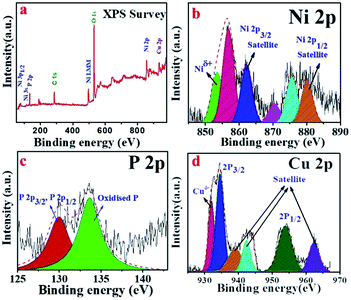 | ||
| Fig. 4 (a) XPS survey spectra of Cuf@Ni5P4, and high-resolution deconvoluted XPS sspectra for: (b) Ni 2p; (c) P 2p; and (d) Cu 2p. | ||
Electrochemical characterization
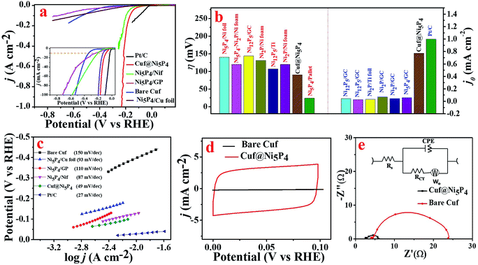
The electrocatalytic activity of the as-prepared catalyst was evaluated by means of the HER in 0.5 M H2SO4. There are only a few reports in the literature of a single-phase synthesis of Ni5P4 used for the generation of H2.16,18 However, all of the reports either failed to achieve a high exchange current density or did not perform for a long time in acidic medium. In order to assess the electrocatalytic activity of the as-prepared Cuf@Ni5P4, a systematic electrochemical characterization for HER was performed. All of the potential used here was converted to the RHE unless mentioned otherwise. The polarization curve of the electrodeposited nickel phosphide on Cuf at different deposition durations (Fig. S10, ESI†), clearly shows that a 90 min deposition time gives the best HER activity in terms of the overpotential and chemical kinetics. As observed from the SEM images (Fig. S3, ESI†), more coverage of electrodeposited Ni5P4 films is obtained with a deposition time of up to 90 min. Further deposition (120 min) inhibits the charge transfer between the Cuf and Ni5P4, which weakens the catalytic performances of the electrode. Fig. 5a displays the obtained polarization curve for Pt/C, Cuf@Ni5P4, Ni5P4/GP, Ni5P4/Cu foil, Ni5P4/Nif and bare Cuf at a scan rate of 10 mV s−1. The Cuf@Ni5P4 catalyst attained an overpotential (η) of 90 mV at a current density of 10 mA cm−2, which is 239 mV more positive than bare Cuf, 148 mV more positive than Ni5P4/GP, 113 mV more positive than Ni5P4/Cu foil, 36 mV more positive than Ni5P4/Nif and 63 mV more negative in comparison to Pt/C. Interestingly, the Cuf@Ni5P4 catalyst displays a η of only 164 mV even at a very high current density of 100 mA cm−2. It is noteworthy to mention here that the achieved overpotential of Cuf@Ni5P4 is very low compared to the previously reported data on nickel phosphide based electrocatalysts (Fig. 5b and Table S1, ESI†).1,18,38 The excellent electrocatalytic activity of Cuf@Ni5P4 reveals the important role of the core shell nanostructures of the catalyst and confirms that the surface nickel phosphide (shell) exploited the copper (core) in terms of the porosity and surface area, resulting in a superior catalytic performance of these a core/shell nanostructures. The HER electrocatalytic activity crucially depends on the uneven electrode surface.39The corresponding Tafel plots were employed to determine the kinetics of the HER rate for the different catalysts (Fig. 5c). The Tafel slope for Cuf@Ni5P4 derived from the Tafel plot was found to be 49 mV dec−1, which is less than that of the Ni5P4/Cu foil (slope = 93 mV dec−1), Ni5P4/GP (110 mV dec−1), Ni5P4/Nif (87 mV dec−1) and bare Cuf (150 mV dec−1), which determines the better kinetic rate of Cuf@Ni5P4 for hydrogen generation. However, the Tafel slope of Pt/C was found to be 27 mV dec−1.
An electrode with a larger exchange current density needs less driving force (smaller current density) to conduct the HER.40 The exchange current density of Cuf@Ni5P4 was calculated to be 0.76 mA cm−2 by extrapolating the linear part of the Tafel plot to the X-axis and it was found to be very close to that of the exchange current density of Pt/C (1.00 mA cm−2) in 0.5 M H2SO4 (Fig. S11, ESI†). The exchange current density achieved by Cuf@Ni5P4 was the highest in comparison with the recently reported nickel phosphide based electrocatalysts38,41–43 (Table S2, ESI†). The exchange current density is usually expressed in terms of the projected or geometric surface area and depends on the surface roughness or roughness factor (RF) of the catalyst.37 The porous nature of the nanostructure offers a high electrochemically active surface area (ECSA) and leads to more electrochemically active sites that undoubtedly help to improve the electrocatalytic activity.44 A comparative CV scan was performed to calculate the ECSA and RF of Cuf@Ni5P4 (Fig. 5d). The CV response obtained from Cuf@Ni5P4 at different scan rates in a non-faradic region (0 to 0.1 V) and the corresponding scan rate versus the anodic and cathodic peak current for the calculation of the value of the double layer capacitance (Cdl) are shown Fig. S12 (ESI†). The ECSA was calculated and found to be 423.5 cm2 by considering the Cdl of 33.9 mF cm−2 and the specific capacitance (Csp = 0.02 mF cm−2) of the Ni surface in the 0.5 M H2SO4 electrolyte.45 The RF was calculated to be 1694 (see ESI† for details), which is very high and outperforms the state-of-the-art catalysts reported to date.46–50
To study the electrode kinetics (charge transfer behavior), EIS of the bare Cuf and Cuf@Ni5P4 (Fig. 5e) were recorded at −0.2 V (vs. RHE). An equivalent circuit model was employed to fit the Nyquist plot as shown in the inset of Fig. 5e. Interestingly, Cuf@Ni5P4 possesses a very small solution resistance (Rs = 2.59 Ω) which indicates a reduced interfacial resistance and the superior catalytic activity of the as-prepared catalyst. The charge transfer resistance (Rct) of Cuf@Ni5P4 was only 3.62 Ω (giving rise to the rapid charge transfer kinetics), which is much lower than that of bare Cuf (Rct = 20 Ω). The EIS of the nickel phosphide deposited on Cuf for different periods of time (Fig. S13, ESI†), clearly indicates that the minimum Rct of Cuf@Ni5P4 with a 90 min deposition time was obtained as compared to the other catalyst. The low Rs and Rct value of Cuf@Ni5P4 ensures the fast charge transfer kinetics between the catalyst and the electrolyte, as well as the catalyst to the electrode, which facilitates the faster reaction rate. It is generally accepted that small values of Rs correspond to close contact between the current collector and catalysts.
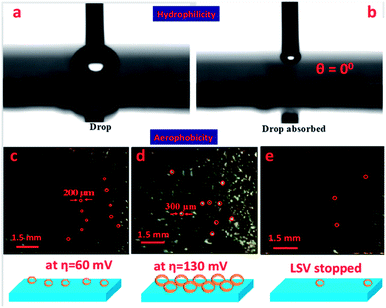
During the catalytic process, plenty of bubbles are generated from the surface of the electrode which blocks electrolyte diffusion and increases the ohmic resistance between the electrode and the electrolyte interfaces, which decreases the ECSA and eventually leads to degradation of the catalytic performance. To overcome this challenge, it is necessary to design a fine surface catalyst which is hydrophilic as well as aerophobic in nature.51 To understand the hydrophilicity of the as-synthesized catalyst, wettability analysis on the surface of the Cuf@Ni5P4 electrode was performed by measuring the contact angle of the water drop on the surface of the catalyst. Fig. 6a shows that the droplet imposes no contact with the surface of Cuf@Ni5P4 and when the drop falls on the surface, the Cuf@Ni5P4 catalyst absorbed the liquid drop instantly (Fig. 6b) with a contact angle of 0°, indicating that the material is superhydrophilic in nature. An aerophobic study of the catalyst was also performed by analysing the bubble formation during and after the LSV run, demonstrated in Fig. 6c–e. The aerophobic nature of the foam-like Cuf@Ni5P4 core–shell nanostructure provides an abrupt renewal of the gas bubbles (as schematically shown in the bottom panel of Fig. 6),52 which helps to increase the efficiency of the catalyst towards hydrogen evolution. When the HER process has just started the average size of the bubbles formed on the surface were approximately 200 μm at an overpotential of approximately 60 mV and the size starts to increase and is observed to be approximately 300 μm at an overpotential of approximately 130 mV, which is due to the rapid renewal of the minor gas bubbles. Interestingly, when the LSV was stopped it was observed that only a few bubbles, which were trapped in the pores, were seen resembling the superior aerophobic behavior of the catalyst. The superhydrophilic and aerophobic nature of the sample originated from the fine nanostructures and selection of an appropriate material is crucial for HER electrocatalysis.
To ascertain the origin of the high electrocatalytic activity in the as-synthesized materials and to deepen the understanding of the HER mechanism, DFT calculations were performed. As established, the electrochemical reduction of ionic hydrogen on a metal-catalyst surface is a combination of a hydrogen adsorption process called the Volmer reaction step followed by either the Tafel or Heyrovsky reaction mechanism for H2 desorption (see ESI† for details). The H* (in which * refers to atomic hydrogen over the surface of the catalyst) is the rate determining step for proton adsorption in an acidic medium. To estimate the hydrogen adsorption energy (EAds.) and the ΔGH* of the reaction intermediate, H*, different metal-catalyst surfaces were explored using the computational hydrogen electrode model proposed by Nørskov et al.53 as follows:
| ΔGH* = EAds. + ΔEZPE − TΔS |
| EAds. = Esurface+H − Esurface − 1/2EH2 |
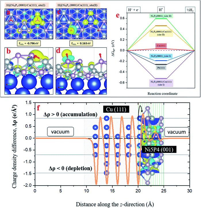
In order to explore the HER activity of the pure Ni5P4 (0001) and Ni5P4 (0001)/Cu (111) hybrid catalyst surface, several hydrogen adsorption sites around the surface Ni and P atoms in the optimized geometry of the Ni5P4 (0001) surface (Fig. S14, ESI†) have been considered to rule out the most probable ones. As demonstrated in Fig. 3i and j, the (001) plane of Ni5P4 is present at the Cuf@Ni5P4 interface. Fig. S15 in ESI† describes how the three-fold Ni hollow site (site I) and the on-top P site (site II) turn out to be the two most favorable hydrogen adsorption sites with binding energies of −0.54 eV and 0.21 eV, respectively. These adsorption sites have been used for further studies on the Ni5P4 (0001)/Cu (111) hybrid interface structure with the Cu (111) surface underneath the Ni5P4 (0001) surface. Fig. 7a and b shows the adsorption geometry of H* on the three-fold Ni site (site I) of Ni5P4 (0001)/Cu (111) with a binding energy of −0.79 eV, which is the highest among all of the surfaces explored in this study, indicating the importance of Cuf support in facilitating the HER activity in the Ni5P4 nanostructures. Similar to the hydrogen adsorption over the on-top P site (site II) of Ni5P4 (0001), the interface structure of Ni5P4 (0001)/Cu (111) also exhibits a positive H binding energy of 0.16 eV with a strong delocalization of the valence charge density around the P atom, as shown in Fig. 7c and d. Details of the H* adsorption on various metal-catalyst surfaces and computational details have been provided in the ESI (Fig. S15, S16, and Table S3, ESI†).
The change in the Gibbs free energy (ΔGH*) of the reaction intermediate, for example H*, is a well-known descriptor of the HER activity of any adsorbate (1/2EH2 in this case) over a metal-catalyst surface. According to the Sabatier principle, a good catalyst should have a ΔGH* value as close as possible to 0 eV. The ΔGH* of the reaction intermediate H* on different metal-catalyst surfaces was measured. The Ni5P4 (0001) and Ni5P4 (0001)/Cu (111) surface with H* adsorbed over the three-fold Ni site (site I) exhibited a negative value of ΔGH*, favoring the HER activity (Fig. 7e). In addition, the negative value of ΔGH* was found to be much higher (−0.52 eV) for the Ni5P4 (0001)/Cu (111) surface as compared to the value of −0.18 eV for the Ni5P4 (0001) surface. This is attributable to a very high negative adsorption energy, EAds. = −0.79 eV of H* over the Ni5P4 (0001)/Cu (111) surface and a localized charge density distribution around the three-fold Ni site of the adsorbate, which strongly binds the atomic hydrogen to its surface (Fig. 7a and b). While for H* at the on-top P site of Ni5P4 (0001) and the Ni5P4 (0001)/Cu (111) surface, a very high positive value of ΔGH* indicates a much weaker binding of H* or a reduction in the desorption of hydrogen, resulting in a much lower HER activity. The adsorption geometry of H* on the three-fold Ni site (site I) of Ni5P4 (0001)/Cu (111) with a binding energy of −0.79 eV, which is the highest among all of the surfaces explored in this study, indicates the importance of Cuf for the deposition of Ni5P4 nanostructures towards HER activity. The high value of the H-binding energy results from the charge transfer between Cu (111) and Ni5P4 (0001), as the interface is chemical in nature. The interfacial study of the Cuf@Ni5P4 was validated by the interfacial charge density distribution. The interface between Cu and Ni5P4 was found to be chemical in nature as shown in Fig. 7f. The charges accumulating at the Cuf@Ni5P4 interface are transferred from the portion of the Cu (111) surface, which in turn, becomes depleted. The difference in the charge density distribution was calculated via Δρ = ρ[interface system] − ρ[Cu (111)] − ρ[Ni5P4 (001)]. This calculation is based on the explicit inclusion of the vDW-D3 dispersive interactive forces, which accounts for the long range electronic interactions in the surface geometries.
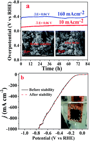
The electrochemical stability or durability of the catalyst in the working electrolyte is an important parameter that one should look for in a catalyst. The chronopotentiometry test was performed to check the durability of the Cuf@Ni5P4 catalyst at a low (10 mA cm−2) as well as high current density (160 mA cm−2) in 0.5 M H2SO4 for 84 h. As demonstrated in Fig. 8a, the electrocatalyst showed an excellent stability performance with approximately 96% retention of the overpotential even at a high current density of 160 mA cm−2. The LSV pattern of the Cuf@Ni5P4 catalyst was recorded before and after the chronoamperometry study and found a minute change in the overpotential as shown in Fig. 8b, which indicates the excellent durability of the catalyst. In order to check the structural integrity of the catalyst during the stability test, SEM (Fig. 8a, inset) as well as elemental mapping analysis (Fig. S17, ESI†) were performed before and after the chronoamperometry test. The SEM study confirmed the morphology of the catalyst is not altered upon continuous evolution (84 h) of hydrogen gas. Elemental mapping further revealed the presence of Ni, Cu and P even after 84 h of the chronoamperometry test, which proved the structural integrity and superior durability of the Cuf@Ni5P4 catalyst. The ultrathin deposited layer (30 nm) of the catalyst on the Cuf could increase the contact area between them and thus decrease the average stress suffered by the hosts upon H2 generation ensuring excellent structural integrity during continuous gas evolution by the as-prepared catalyst. The excellent durability, along with the outstanding catalytic activity of the catalyst, opens up a new method for the electrochemical generation of hydrogen.
Conclusions
In summary, we present here a simple electrochemical approach to design a single-phase Ni5P4 catalyst deposited on a galvanostatically-grown Cuf nanoarchitecture. The core–shell Cuf@Ni5P4 catalyst showed a high catalytic activity towards HER in acidic medium with a significantly reduced overpotential and a superior exchange current density. The high ECSA and excessive RF that originates from the foam-like surface of Cuf is essentially responsible for the high electrocatalytic activity of the catalyst. DFT calculations elucidated the origin of a very high negative ΔGH* in Ni5P4 (0001)/Cu (111) upon hydrogen adsorption. This arises owing to a localized charge density distribution around the three-fold Ni site of the adsorbate, which is favorable for the HER activity of the catalyst. The superhydrophilic and aerophobic nanostructured surface actually helps by reducing the contact resistance and the fast release of air bubbles during the catalysis process. Moreover, the Cuf@Ni5P4 catalyst shows a long-term durability of 84 h measured using a chronopotentiometry test at a low and high current density with approximately 96% retention of the initial overpotential and preserving the structural consistency, which strongly indicates the superiority of the catalyst. This study opens up a new route for the synthesis of efficient and robust catalysts for the generation of H2 in a cost-effective and less time-consuming pathway, which will have encouraging future applications in the field of renewable energy.Conflicts of interest
There are no conflicts to declare.Acknowledgements
MD acknowledges SERB EMR and INST, Mohali for providing fellowship. This work was financially supported by the DST SERB EMR (EMR/2016/000040) and DST INSPIRE (DST/INSPIRE/04/2015/000337) funding agencies. The authors acknowledge INST, Mohali for instrumental support. Our sincere thanks are extended to CDAC, Pune's supercomputing resources on PARAM YUVA II for the theoretical calculations.Notes and references
- X. Wang, Y. V. Kolen'Ko, X. Q. Bao, K. Kovnir and L. Liu, Angew. Chem., Int. Ed., 2015, 54, 8188–8192 CrossRef CAS PubMed.
- X. Wang, W. Li, D. Xiong, D. Y. Petrovykh and L. Liu, Adv. Funct. Mater., 2016, 26, 4067–4077 CrossRef CAS.
- P. W. Menezes, A. Indra, C. Das, C. Walter, C. Göbel, V. Gutkin, D. Schmeißer and M. Driess, ACS Catal., 2017, 7, 103–109 CrossRef CAS.
- S. Anantharaj, S. R. Ede, K. Sakthikumar, K. Karthick, S. Mishra and S. Kundu, ACS Catal., 2016, 6, 8069–8097 CrossRef CAS.
- Y. Pan, Y. Liu, J. Zhao, K. Yang, J. Liang, D. Liu, W. Hu, D. Liu, Y. Liu and C. Liu, J. Mater. Chem. A, 2015, 3, 1656–1665 RSC.
- J. Li, J. Li, X. Zhou, Z. Xia, W. Gao, Y. Ma and Y. Qu, ACS Appl. Mater. Interfaces, 2016, 8, 10826–10834 CrossRef CAS PubMed.
- A. Han, H. Chen, Z. Sun, J. Xu and P. Du, Chem. Commun., 2015, 51, 11626–11629 RSC.
- D. Li, K. Senevirathne, L. Aquilina and S. L. Brock, Inorg. Chem., 2015, 54, 7968–7975 CrossRef CAS PubMed.
- I. K. Mishra, H. Zhou, J. Sun, F. Qin, K. Dahal, J. Bao, S. Chen and Z. Ren, Energy Environ. Sci., 2018, 11, 2246–2252 RSC.
- P. Liu and J. A. Rodriguez, J. Am. Chem. Soc., 2005, 127, 14871–14878 CrossRef CAS PubMed.
- P. Wang, Z. Pu, Y. Li, L. Wu, Z. Tu, M. Jiang, Z. Kou, I. S. Amiinu and S. Mu, ACS Appl. Mater. Interfaces, 2017, 9, 26001–26007 CrossRef CAS PubMed.
- C. Du, M. Shang, J. Mao and W. Song, J. Mater. Chem. A, 2017, 5, 15940–15949 RSC.
- X. Xiao, D. Huang, Y. Fu, M. Wen, X. Jiang, X. Lv, M. Li, L. Gao, S. Liu, M. Wang, C. Zhao and Y. Shen, ACS Appl. Mater. Interfaces, 2018, 10, 4689–4696 CrossRef CAS PubMed.
- B. You, N. Jiang, M. Sheng, M. W. Bhushan and Y. Sun, ACS Catal., 2016, 6, 714–721 CrossRef CAS.
- J. Xu, J. P. S. Sousa, N. E. Mordvinova, J. D. Costa, D. Y. Petrovykh, K. Kovnir, O. I. Lebedev and Y. V. Kolen'Ko, ACS Catal., 2018, 8, 2595–2600 CrossRef CAS.
- A. B. Laursen, K. R. Patraju, M. J. Whitaker, M. Retuerto, T. Sarkar, N. Yao, K. V. Ramanujachary, M. Greenblatt and G. C. Dismukes, Energy Environ. Sci., 2015, 8, 1027–1034 RSC.
- C. Lai, X. Liu, Y. Deng, H. Yang, H. Jiang, Z. Xiao and T. Liang, Inorg. Chem. Commun., 2018, 97, 98–102 CrossRef CAS.
- M. Ledendecker, S. Krick Calderón, C. Papp, H.-P. Steinrück, M. Antonietti and M. Shalom, Angew. Chem., Int. Ed., 2015, 54, 12361–12365 CrossRef CAS PubMed.
- N. A. C. Hirst, in The Energy Conundrum, World Scientific (Europe), 2018, pp. 119–190 Search PubMed.
- S. J. Hwang, S. J. Yoo, J. Shin, Y.-H. Cho, J. H. Jang, E. Cho, Y. Sung, S. W. Nam, T. Lim, S. Lee and S. Kim, Sci. Rep., 2013, 3, 1309 CrossRef PubMed.
- M. B. Gawande, A. Goswami, T. Asefa, H. Guo, A. V. Biradar, D. Peng, R. Zboril and R. S. Varma, Chem. Soc. Rev., 2015, 44, 7540–7590 RSC.
- Z. Lu, W. Zhu, X. Yu, H. Zhang, Y. Li, X. Sun, X. Wang, H. Wang, J. Wang, J. Luo, X. Lei and L. Jiang, Adv. Mater., 2014, 26, 2683–2687 CrossRef CAS PubMed.
- T. Purkait, G. Singh, D. Kumar, M. Singh and R. S. Dey, Sci. Rep., 2018, 8, 640 CrossRef PubMed.
- G. Kresse and J. Furthmüller, Phys. Rev. B: Condens. Matter Mater. Phys., 1996, 54, 11169–11186 CrossRef CAS PubMed.
- P. E. Blöchl, Phys. Rev. B: Condens. Matter Mater. Phys., 1994, 50, 17953–17979 CrossRef PubMed.
- D. Joubert, Phys. Rev. B: Condens. Matter Mater. Phys., 1999, 59, 1758–1775 CrossRef.
- J. P. Perdew, K. Burke and M. Ernzerhof, Phys. Rev. Lett., 1996, 77, 3865–3868 CrossRef CAS PubMed.
- B. D. Cullity and S. R. Stock, Elements of X-ray Diffraction, 2nd edn, 1978 Search PubMed.
- I. Meunier, G. Tréglia, J.-M. Gay, B. Aufray and B. Legrand, Phys. Rev. B: Condens. Matter Mater. Phys., 1999, 59, 10910–10917 CrossRef CAS.
- S. Shao, J. Shao, H. He and Z. Fan, Opt. Lett., 2005, 30, 2119 CrossRef CAS PubMed.
- K. Neuróhr, L. Pogány, B. G. Tóth, Á. Révész, I. Bakonyi and L. Péter, J. Electrochem. Soc., 2015, 162, D256–D264 CrossRef.
- X. Ma, Y. Chang, Z. Zhang and J. Tang, J. Mater. Chem. A, 2018, 6, 2100–2106 RSC.
- R. S. Dey, H. A. Hjuler and Q. Chi, J. Mater. Chem. A, 2015, 3, 6324–6329 RSC.
- J. Jiang, C. Wang, W. Li and Q. Yang, J. Mater. Chem. A, 2015, 3, 23345–23351 RSC.
- P. W. Menezes, A. Indra, C. Das, C. Walter and C. Göbel, ACS Catal., 2017, 7(1), 103–109 CrossRef CAS.
- S. Wei, K. Qi, Z. Jin, J. Cao, W. Zheng, H. Chen and X. Cui, ACS Omega, 2016, 1, 1367–1373 CrossRef CAS.
- J. Tian, Q. Liu, N. Cheng, A. M. Asiri and X. Sun, Angew. Chem., Int. Ed., 2014, 53, 9577–9581 CrossRef CAS PubMed.
- Z. Huang, Z. Chen, Z. Chen, C. Lv, H. Meng and C. Zhang, ACS Nano, 2014, 8, 8121–8129 CrossRef CAS PubMed.
- M. H. Suliman, A. Adam, M. N. Siddiqui, Z. H. Yamani and M. Qamar, Catal. Sci. Technol., 2019, 9, 1497–1503 RSC.
- Y. Pan, Y. Liu, J. Zhao, K. Yang, J. Liang, D. Liu, W. Hu, D. Liu, Y. Liu and C. Liu, J. Mater. Chem. A, 2015, 3, 1656–1665 RSC.
- T. Tian, L. Ai and J. Jiang, RSC Adv., 2015, 5, 10290–10295 RSC.
- Y. Pan, Y. Liu, J. Zhao, K. Yang, J. Liang, D. Liu, W. Hu, D. Liu, Y. Liu and C. Liu, J. Mater. Chem. A, 2015, 3, 1656–1665 RSC.
- E. J. Popczun, J. R. McKone, C. G. Read, A. J. Biacchi, A. M. Wiltrout, N. S. Lewis and R. E. Schaak, J. Am. Chem. Soc., 2013, 135, 9267–9270 CrossRef CAS PubMed.
- C. C. Chusuei, M. A. Brookshier and D. W. Goodman, Langmuir, 1999, 15, 2806–2808 CrossRef CAS.
- C. C. L. McCrory, S. Jung, J. C. Peters and T. F. Jaramillo, J. Am. Chem. Soc., 2013, 135, 16977–16987 CrossRef CAS PubMed.
- J. Chang, K. Li, Z. Wu, J. Ge, C. Liu and W. Xing, ACS Appl. Mater. Interfaces, 2018, 10, 26303–26311 CrossRef CAS PubMed.
- L. Wei, K. Goh, Ö. Birer, H. E. Karahan, J. Chang, S. Zhai, X. Chen and Y. Chen, Nanoscale, 2017, 9, 4401–4408 RSC.
- J. Chang, K. Li, Z. Wu, J. Ge, C. Liu and W. Xing, ACS Appl. Mater. Interfaces, 2018, 10, 26303–26311 CrossRef CAS PubMed.
- Y. Yang, H. Fei, G. Ruan and J. M. Tour, Adv. Mater., 2015, 27, 3175–3180 CrossRef CAS PubMed.
- A. Dutta, A. K. Samantara, S. K. Dutta, B. K. Jena and N. Pradhan, ACS Energy Lett., 2016, 1, 169–174 CrossRef CAS.
- Y. Shi and B. Zhang, Chem. Soc. Rev., 2016, 45, 1529–1541 RSC.
- H. Li, S. Chen, Y. Zhang, Q. Zhang, Q. Zhang, X. Jia, L. Gu, X. Sun, L. Song and X. Wang, Nat. Commun., 2018, 9, 1–12 CrossRef PubMed.
- J. Greeley, T. F. Jaramillo, J. Bonde, I. Chorkendorff and J. K. Nørskov, Nat. Mater., 2006, 5, 909–913 CrossRef CAS PubMed.
Footnote |
| † Electronic supplementary information (ESI) available. See DOI: 10.1039/c9ta06729a |
| This journal is © The Royal Society of Chemistry 2019 |


