 Open Access Article
Blade-coated perovskite nanoplatelet polymer composites for sky-blue light-emitting diodes†
Jiale
Chen
a,
Jiaxiong
Li
 a,
Georgian
Nedelcu
b,
Paul
Hansch
a,
Lorenzo
Di Mario
a,
Georgian
Nedelcu
b,
Paul
Hansch
a,
Lorenzo
Di Mario
 a,
Loredana
Protesescu
 b and
Maria A.
Loi
 *a
*a
aPhotophysics & OptoElectronics, Zernike Institute for Advanced Materials, University of Groningen, Nijenborgh 3, 9747AG, Groningen, The Netherlands. E-mail: M.A.Loi@rug.nl
bMaterials Chemistry, Zernike Institute for Advanced Materials, University of Groningen, Nijenborgh 3, 9747AG, Groningen, The Netherlands
First published on 31st July 2024
Abstract
Colloidal perovskite nanoplatelets (NPLs) have shown promise in tackling blue light-emitting diode challenges based on their tunable band gap and high photoluminescence efficiencies. However, high quality and large area dense NPL films have been proven to be very hard to prepare because of their chemical and physical fragility during the liquid phase deposition. Herein, we report a perovskite-polymer composite film deposition strategy with fine morphology engineering obtained using the blade coating method. The effects of the polymer type, solution concentration, compounding ratio and film thickness on the film quality are systematically investigated. We found that a relatively high-concentration suspension with an optimized NPL to polymer ratio of 1![[thin space (1/6-em)]](https://www.rsc.org/images/entities/char_2009.gif) :
:![[thin space (1/6-em)]](https://www.rsc.org/images/entities/char_2009.gif) 2 is crucial for the suppression of phase separation and arriving at a uniform film. Finally, sky-blue NPL-based perovskite light-emitting diodes were fabricated by blade coating showing an EQE of 0.12% on a device area of 16 mm2.
2 is crucial for the suppression of phase separation and arriving at a uniform film. Finally, sky-blue NPL-based perovskite light-emitting diodes were fabricated by blade coating showing an EQE of 0.12% on a device area of 16 mm2.
1 Introduction
Colloidal lead halide perovskite nanocrystals (PNCs) can be easily synthesized in liquid phase reactions (hot injection) and due to their prominent optoelectronic properties, such as high photoluminescence quantum yield (PLQY), tunable band gap and narrow emission spectra, they are promising materials for the fabrication of light-emitting diodes.1–5 Specifically, by taking advantage of the precise crystal size control obtained by tuning the parameters of the hot-injection reaction, PNCs and nanoplatelets (NPLs) displaying spectrally stable blue-light emission can be obtained.5–11 In particular, bromide-based two-dimensional perovskite NPLs have been reported to display a PLQY above 80%, with an adjustable emitting wavelength from 425 nm to 520 nm through altering the layer numbers,12–14 showing the potential of achieving the same level of performance in phase-pure quasi-2D perovskite thin films.15,16So far, many investigations have been devoted to changing the organic ligands on the PNC surface to enhance the efficiency of NPL-based perovskite light-emitting diodes (PeLEDs), since the consensus is that the low electrical conductivity of the organic ligand at the surface is the main limiting factor in device performance.17,18 However, few reports have focused on the quality of NPL thin films, which also determines the device efficiency.19–23 It is clear that to fabricate high-performance blue PeLEDs, high-quality and reproducible thin films are the prerequisites. The film coverage and morphology can be directly associated with the structural integrity of the built-up device and the charge injection and recombination schemes. Previous reports on spin coating deposition methods suggested that NPLs are susceptible to self-aggregation during the film formation process.2,24–27 Poor substrate coverage and large NC agglomerates can often be observed after coating, which could result in high leakage current, low EQE and color stability. This drawback is often regarded as the bottleneck for successful large-area LED manufacturing.
Though most of the top-efficiency PeLEDs were achieved via spin coating, large-area deposition by blade-coating has recently attracted great attention and is deemed more suitable than spin-coating for industrial-scale production, not only because the latter is much more prone to material wasting but also since uneven materials distribution could easily happen during the fast film formation of the composite.28–31 One notable example of blade coating in the fabrication of large-area sky-blue PeLEDs was demonstrated with an active area of 28 cm2.32 A similar approach has also been used for colloidal PNCs by using a bar-coating process, with which highly efficient green PeLEDs (22.5% EQE) with an area of 102 mm2 (ref. 30) were achieved. Yet to date, it is still a great challenge to blade-coat a conductive thin film (<50 nm) composed of a polymer matrix and perovskite nanoparticles with a homogenous morphology. It should be highlighted that much know-how gained from spin-coating may not be directly transferred to blade-coating fabrication. One of the most important features is that the latter is in thermodynamic equilibrium with the solvent removal obtained only by tuning the temperature of the substrate. It is also important to note that blade-coated films containing quantum-confined perovskite NPLs for blue LEDs are still to be demonstrated.
Our strategy to obtain uniform and pinhole-free NPL perovskite thin films is to blend the NPLs with a hole-transport polymer of wide band gap. Using a polymeric matrix can help to stabilize the perovskite nanostructures and enhance the charge transport of the active layer where NPLs still have the original ligands.19,22,33 In fact, colloidal NPLs are easy to aggregate due to the loss of ligands and confinement during the film's formation, which may result in strong non-radiative recombination and inadequate film morphology.21,33,34 In 2016, Gao and colleagues used poly(ethylene oxide) to obtain small microcrystalline perovskite domains and pinhole-free surfaces and realized high-efficiency green PeLEDs.35 Zhong and co-workers have shown that using polyvinylidene fluoride improves both the PL properties and air stability of the nanocrystal/polymer composite film.36 Jiang and co-workers used this strategy to prepare a FAPbI3 quantum dot composite film with poly(methyl methacrylate) showing no microscopic aggregation with a minor red-shift in PL from 529 nm to 534 nm.33 However, there is very little or no success reported on the use of NPL-polymer composites for PeLEDs.
In this work, we demonstrate a convenient strategy for preparing uniform and non-aggregated blue-emitting CsPbBr3 NPL/polymer composite thin films via blade-coating at room temperature. Two very common hole transport polymers, namely, poly(9-vinylcarbazole) (PVK) and poly(4-butyl-N,N-diphenylamine) (P-TPD), were each used as a matrix to form corresponding composite films with NPLs. Important factors, including the selection of the polymer, the concentration of solution, the ratio of NPL to polymer, and the composite film thickness, are systematically investigated, aiming for a homogeneous morphology by blade-coating.37 Our study revealed that using a compatible polymer in a highly concentrated suspension is indispensable for suppressing phase separation and forming conformal and compact films. The optimal ratio and concentration of NPLs and P-TPD yielded promising electroluminescence properties leading to PeNPLLED devices with an EQE of 0.12% at 16 mm2 area. The electrical properties and photophysics of these high-quality films are discussed in relationship with the device performance.
2. Results and discussion
In this work, CsPbBr3 NPLs were synthesized following a procedure reported elsewhere (consult the ESI† for the detailed procedure).38,39Fig. 1a shows the optical properties of our NPLs measured in suspension showing 72% photoluminescence quantum yield (PLQY). Fig. 1b schematically depicts the steps involved in the ink preparation and deposition process to obtain the thin films. The ink is made by mixing freshly synthesized NPLs (see the Experimental section in the ESI†) bearing oleic acid and oleylamine ligands with the polymer at specific ratios and concentrations under a nitrogen atmosphere. The blade-coating setting and the concentration of NPL solution can significantly affect the morphology of the nanocomposite films, which we will discuss below.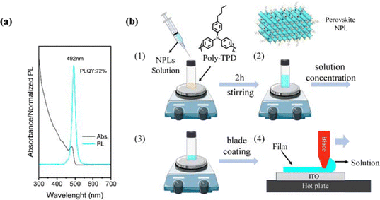 | ||
| Fig. 1 (a) Absorption and PL spectra of CsPbBr3 NPLs. (b) Schematic representation for polymer/NPLs composite solution preparation (ink) and the doctor-blading process for deposition. | ||
Many reports have found that closed NPL films were very hard to prepare starting from low-concentration solutions18,40 such as 5 mg mL−1. However, when increasing the concentration of NPL suspension from 5 mg mL−1 to 20 mg mL−1, severe aggregation and followed by precipitation of the NPLs is observed. In our experiments, two different concentrations of NPL suspensions (5 mg mL−1 and 15 mg mL−1) were prepared to investigate their film formation behavior in blade coating. The optical-microscopy study revealed aggregation behavior in the film prepared by the high-concentrated suspensions (Fig. S1, ESI†). We, therefore, seek to select a proper conductive polymer that can provide a conductive matrix to embed the NPLs and that is soluble in the same solvent.
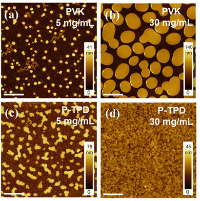
Common HTL materials, such as PVK and P-TPD, were selected as the matrix since both have a high electrical conductivity and good energy level matching with NPLs41 to form a type one heterostructure. Their solubility in toluene assists a facile blending with NPLs in the solvent of choice. Atomic force microscopy (AFM) was used to study the morphology of blade-coated films from NPL blends with different polymers. The topography of films deposited from NPL-PVK inks (10 mg mL−1 for NPLs and 5 mg mL−1 for PVK) (Fig. 2a) exhibits serious phase separation with many randomly distributed islands of round shape, which are probably composed of polymer. When the concentration of PVK is increased from 5 mg mL−1 to 30 mg mL−1 (Fig. 2b), the phase separation is not improved, but the size of the polymer islands increased from 300 nm to 1 μm on average. Therefore, regardless of the starting ratio, the combination between PVK and the perovskite NPLs doesn’t lead to homogeneous films. In the case of P-TPDP-TPD-based thin films, similar phase-separation is observed for low concentrations of P-TPDP-TPD (5 mg mL−1), Fig. 2c, but the morphology of these samples appeared substantially different than the one of the samples based on PVK, showing more dendritic like polymer structures. However, when the concentration of P-TPD is increased from 5 mg mL−1 to 30 mg mL−1, the film quality notably improves, showing a rather homogeneous and compact morphology, displayed in Fig. 2d. This observation is in line with other studies reporting dramatically different morphologies of colloidal PNCs when spin-coated on PVK or P-TPD layers.42 Such a drastic difference was mainly attributed to the better affinity of P-TPD towards the NCs ligands, contributing to an increase in the miscibility of the hetero-phases at high polymer concentrations. At the same time, the mixing of the NPLs with PVK may be limited by its bulky side groups. These favorable behaviors recommend P-TPD as the preferred candidate for compounding with perovskite NPLs. Therefore, we carried out further optimizations of NPLs/P-TPD systems, and we focused on understanding the critical parameters determining the film morphology, the absolute concentration of polymer and NPLs, and the polymer-to-NPL ratio.
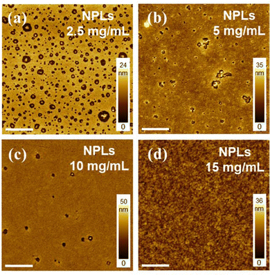
In the blade-coating process, the concentration of the suspension can have a significant effect on the solvent evaporation rate and rheological behavior, all being important parameters that affect the morphology of the formed film.28,30,43 Suspensions with NPL concentrations of 2.5 mg mL−1, 5 mg mL−1, 10 mg mL−1, and 15 mg mL−1 with a fixed NPL to polymer ratio of 1![[thin space (1/6-em)]](https://www.rsc.org/images/entities/char_2009.gif) :
:![[thin space (1/6-em)]](https://www.rsc.org/images/entities/char_2009.gif) 2 were prepared and used to investigate this phenomenon. All the samples were blade-coated with the same speed and blade height, and the corresponding AFM micrographs are reported in Fig. 3. As shown in Fig. 3a, an uneven surface showing scattered holes of different sizes was observed for films using low-concentration NPLs (2.5 mg mL−1). AFM images in Fig. S2 (ESI†) indicate that aggregates of NPLs are most probably located inside the holes. We believe this results from a combination of incomplete film coverage and the self-aggregation properties of NPLs at low concentrations. When increasing the solution concentration from 2.5 mg mL−1 to 5 mg mL−1 and 10 mg mL−1, the number of the holes gradually decreases, and their diameter also decreases as shown in Fig. 3b and 3c. Finally, at 15 mg mL−1 (Fig. 3d), the film shows a smooth and pinhole-free surface. We concluded that blade coating with high-concentration NPLs/polymer blends is essential to obtain continuous films with good morphology.
2 were prepared and used to investigate this phenomenon. All the samples were blade-coated with the same speed and blade height, and the corresponding AFM micrographs are reported in Fig. 3. As shown in Fig. 3a, an uneven surface showing scattered holes of different sizes was observed for films using low-concentration NPLs (2.5 mg mL−1). AFM images in Fig. S2 (ESI†) indicate that aggregates of NPLs are most probably located inside the holes. We believe this results from a combination of incomplete film coverage and the self-aggregation properties of NPLs at low concentrations. When increasing the solution concentration from 2.5 mg mL−1 to 5 mg mL−1 and 10 mg mL−1, the number of the holes gradually decreases, and their diameter also decreases as shown in Fig. 3b and 3c. Finally, at 15 mg mL−1 (Fig. 3d), the film shows a smooth and pinhole-free surface. We concluded that blade coating with high-concentration NPLs/polymer blends is essential to obtain continuous films with good morphology.
Intuitively, a higher NPL ratio in the binary system is preferred for strong and clean emissions, though clearly the film quality and the NPL dispersion/connectivity are also expected to strongly determine the device performance. It is thus essential to explore the threshold ratio of NPLs to polymer, above which a well-mixed film cannot be achieved. Based on the concentration optimizations described earlier (15 mg mL−1 NPLs), we prepared four blends with this concentration and different NPLs to polymer ratios (1![[thin space (1/6-em)]](https://www.rsc.org/images/entities/char_2009.gif) :
:![[thin space (1/6-em)]](https://www.rsc.org/images/entities/char_2009.gif) 1.6, 1
1.6, 1![[thin space (1/6-em)]](https://www.rsc.org/images/entities/char_2009.gif) :
:![[thin space (1/6-em)]](https://www.rsc.org/images/entities/char_2009.gif) 1.8, 1
1.8, 1![[thin space (1/6-em)]](https://www.rsc.org/images/entities/char_2009.gif) :
:![[thin space (1/6-em)]](https://www.rsc.org/images/entities/char_2009.gif) 2.0, and 1
2.0, and 1![[thin space (1/6-em)]](https://www.rsc.org/images/entities/char_2009.gif) :
:![[thin space (1/6-em)]](https://www.rsc.org/images/entities/char_2009.gif) 2.2). The target thickness for films is about 45 nm. As shown in Fig. 4a, the composite film blade coated with the 1
2.2). The target thickness for films is about 45 nm. As shown in Fig. 4a, the composite film blade coated with the 1![[thin space (1/6-em)]](https://www.rsc.org/images/entities/char_2009.gif) :
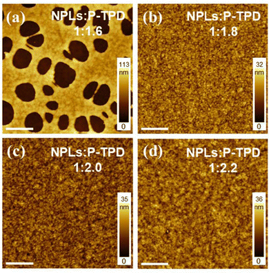
:![[thin space (1/6-em)]](https://www.rsc.org/images/entities/char_2009.gif) 1.6 ratio mixture, (polymer concentration of 24 mg mL−1) exhibited large holes (diameter ∼ 2 μm) on the surface, which is quite different from the low concentration scenario in Fig. 3a. This clean-cut and large-scale pinhole formation could be correlated to an insufficient amount of polymer needed to prevent the self-aggregation of high-concentration NPLs. Fig. 4b shows that increasing the polymer content to NPLs: P-TPD to 1
1.6 ratio mixture, (polymer concentration of 24 mg mL−1) exhibited large holes (diameter ∼ 2 μm) on the surface, which is quite different from the low concentration scenario in Fig. 3a. This clean-cut and large-scale pinhole formation could be correlated to an insufficient amount of polymer needed to prevent the self-aggregation of high-concentration NPLs. Fig. 4b shows that increasing the polymer content to NPLs: P-TPD to 1![[thin space (1/6-em)]](https://www.rsc.org/images/entities/char_2009.gif) :
:![[thin space (1/6-em)]](https://www.rsc.org/images/entities/char_2009.gif) 1.8, resulted in the disappearance of all pinholes and the composite film showed a well-mixed and homogenous surface. This uniform morphology persisted when we further increased the polymer content to 1
1.8, resulted in the disappearance of all pinholes and the composite film showed a well-mixed and homogenous surface. This uniform morphology persisted when we further increased the polymer content to 1![[thin space (1/6-em)]](https://www.rsc.org/images/entities/char_2009.gif) :
:![[thin space (1/6-em)]](https://www.rsc.org/images/entities/char_2009.gif) 2 and 1
2 and 1![[thin space (1/6-em)]](https://www.rsc.org/images/entities/char_2009.gif) :
:![[thin space (1/6-em)]](https://www.rsc.org/images/entities/char_2009.gif) 2.2 ratio (Fig. 4c and d). Based on this trend, we consider that a minimum of 1.8 times the NPL weight of polymer must be included to yield homogeneous blade-coated composite films.
2.2 ratio (Fig. 4c and d). Based on this trend, we consider that a minimum of 1.8 times the NPL weight of polymer must be included to yield homogeneous blade-coated composite films.
In general, thinner active layers are favorable for the confinement and radiative recombination of charge carriers in PeLEDs.44 In blade coating deposition, the final film thickness can be altered with the solution concentration and by tuning the blading speed. The higher the blading speed, the thicker the films will be obtained, as more ink remains behind the blade. We perform experiments to demonstrate the effect of blading speed on the film thickness and morphology. From the above optimization, four different thicknesses (15, 20, 30 and 45 nm) of the composite film were obtained using the optimized mixed solution (c(NPLs) = 15 mg mL−1, NPLs to polymer ratio = 1![[thin space (1/6-em)]](https://www.rsc.org/images/entities/char_2009.gif) :
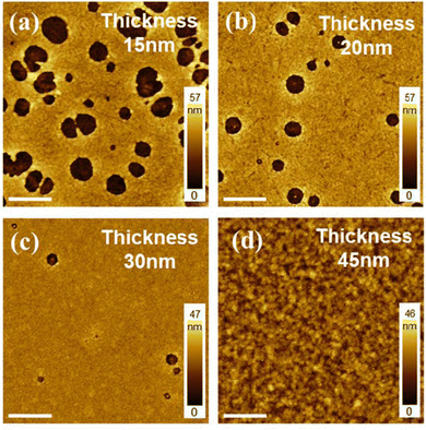
:![[thin space (1/6-em)]](https://www.rsc.org/images/entities/char_2009.gif) 2.0), each at the blading speed of 2 mm s−1, 3 mm s−1, 5 mm s−1 and 10 mm s−1. Their corresponding AFM images are reported in Fig. 5. In Fig. 5a, the composite film of 15 nm thickness showed a large number of holes of about 1 μm diameter on average on the surface. Under such blading conditions, the fast evaporation of solvents may have mimicked the precipitation kinetics in poorly distributed NPL suspensions. By increasing the thickness of the film to 20 nm and 30 nm, not only the number of pinholes but also their sizes (300 nm and 200 nm on average, respectively) significantly decreased. Apparently, maintaining the optimal morphology while achieving thinner active layer thickness is very challenging, and only when reaching 45 nm (Fig. 5d), a homogeneous film can be obtained again. It is expected that for each desired thickness the optimization process described earlier would give rise to a different optimal ratio among the active layer components.
2.0), each at the blading speed of 2 mm s−1, 3 mm s−1, 5 mm s−1 and 10 mm s−1. Their corresponding AFM images are reported in Fig. 5. In Fig. 5a, the composite film of 15 nm thickness showed a large number of holes of about 1 μm diameter on average on the surface. Under such blading conditions, the fast evaporation of solvents may have mimicked the precipitation kinetics in poorly distributed NPL suspensions. By increasing the thickness of the film to 20 nm and 30 nm, not only the number of pinholes but also their sizes (300 nm and 200 nm on average, respectively) significantly decreased. Apparently, maintaining the optimal morphology while achieving thinner active layer thickness is very challenging, and only when reaching 45 nm (Fig. 5d), a homogeneous film can be obtained again. It is expected that for each desired thickness the optimization process described earlier would give rise to a different optimal ratio among the active layer components.
Before attempting the fabrication of light-emitting devices, it is important to measure the photoluminescence properties of the NPL-polymer composite film. Four composite films with different P-TPD ratios (1![[thin space (1/6-em)]](https://www.rsc.org/images/entities/char_2009.gif) :
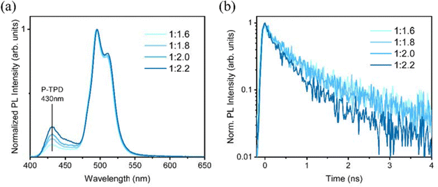
:![[thin space (1/6-em)]](https://www.rsc.org/images/entities/char_2009.gif) 1.6, 1.8, 2.0 and 2.2) were prepared under the same blade coating condition. The steady-state PL (Fig. 6a) shows that for all the films, the emission spectrum is dominated by a peak at around 495 nm, consistent with the PL measurements of the NPLs in solution. However, the spectrum shows a second peak at lower energy, which may derive from energy transfer to a different population of NPLs of slightly different sizes. Furthermore, the steady-state PL (Fig. 6a) shows that a peak at about 430 nm is present in the spectrum for all the samples, and it is increasing intensity as the amount of P-TPD from ratio NPLs: P-TPD increases from 1
1.6, 1.8, 2.0 and 2.2) were prepared under the same blade coating condition. The steady-state PL (Fig. 6a) shows that for all the films, the emission spectrum is dominated by a peak at around 495 nm, consistent with the PL measurements of the NPLs in solution. However, the spectrum shows a second peak at lower energy, which may derive from energy transfer to a different population of NPLs of slightly different sizes. Furthermore, the steady-state PL (Fig. 6a) shows that a peak at about 430 nm is present in the spectrum for all the samples, and it is increasing intensity as the amount of P-TPD from ratio NPLs: P-TPD increases from 1![[thin space (1/6-em)]](https://www.rsc.org/images/entities/char_2009.gif) :
:![[thin space (1/6-em)]](https://www.rsc.org/images/entities/char_2009.gif) 1.6 to 1
1.6 to 1![[thin space (1/6-em)]](https://www.rsc.org/images/entities/char_2009.gif) :
:![[thin space (1/6-em)]](https://www.rsc.org/images/entities/char_2009.gif) 2.22. Since the concentration of P-TPD increases with the ratio while the concentration of NPLs is fixed, the peak is attributed to the emission from P-TPD. In Fig. 6b, we report the time-resolved PL of the different NPLs: P-TPD concentration. The lifetime of photoluminescence can be indicative of the quality of the film, the interaction between the components, and the status of aggregation of the nanoplatelets therein. The decay time of the PL signal of NPLs at 495 nm (Fig. 6b) shows a dependence on their concentration in the film, decreasing faster as the ratio increases. Four composite films with different P-TPD ratios (1
2.22. Since the concentration of P-TPD increases with the ratio while the concentration of NPLs is fixed, the peak is attributed to the emission from P-TPD. In Fig. 6b, we report the time-resolved PL of the different NPLs: P-TPD concentration. The lifetime of photoluminescence can be indicative of the quality of the film, the interaction between the components, and the status of aggregation of the nanoplatelets therein. The decay time of the PL signal of NPLs at 495 nm (Fig. 6b) shows a dependence on their concentration in the film, decreasing faster as the ratio increases. Four composite films with different P-TPD ratios (1![[thin space (1/6-em)]](https://www.rsc.org/images/entities/char_2009.gif) :
:![[thin space (1/6-em)]](https://www.rsc.org/images/entities/char_2009.gif) 1.6, 1.8, 2.0 and 2.2) were prepared under the same blade coating condition. The PL lifetime of such emission, calculated fitting the experimental data with exponential decay, is 1.39ns, 1.32 ns, 1.29 ns and 0.79 ns for ratios of 1
1.6, 1.8, 2.0 and 2.2) were prepared under the same blade coating condition. The PL lifetime of such emission, calculated fitting the experimental data with exponential decay, is 1.39ns, 1.32 ns, 1.29 ns and 0.79 ns for ratios of 1![[thin space (1/6-em)]](https://www.rsc.org/images/entities/char_2009.gif) :
:![[thin space (1/6-em)]](https://www.rsc.org/images/entities/char_2009.gif) 1.6, 1
1.6, 1![[thin space (1/6-em)]](https://www.rsc.org/images/entities/char_2009.gif) :
:![[thin space (1/6-em)]](https://www.rsc.org/images/entities/char_2009.gif) 1.8, 1
1.8, 1![[thin space (1/6-em)]](https://www.rsc.org/images/entities/char_2009.gif) :
:![[thin space (1/6-em)]](https://www.rsc.org/images/entities/char_2009.gif) 2.0 and 1
2.0 and 1![[thin space (1/6-em)]](https://www.rsc.org/images/entities/char_2009.gif) :
:![[thin space (1/6-em)]](https://www.rsc.org/images/entities/char_2009.gif) 2.2, respectively. The decrease of the PL lifetime with the ratio together with a substantial unvaried spectral shape, suggests a competition between NPLs and polymer matrix radiative recombination, with a mechanism of charge or energy transfer possibly involved. Further evidence of energy transfer upon optical excitation can be obtained by comparing the PL of the blend in solution (see Fig. S3a and b, ESI†) and in a thin film (Fig. S3c, ESI†). While in solution, the signals seem to sum, in a thin film, the polymer intensity is much smaller when interacting with the NPLs. However, no evidence of rise time is evident in the NPLs signal, which could be explained by the short-range transfer (high relative ratio of NPLs). Overall, the PL characterization highlights the importance of an optimal nanocomposite mixing towards light-emitting applications. In particular, the PL measurements seem to suggest an upper limit of 1
2.2, respectively. The decrease of the PL lifetime with the ratio together with a substantial unvaried spectral shape, suggests a competition between NPLs and polymer matrix radiative recombination, with a mechanism of charge or energy transfer possibly involved. Further evidence of energy transfer upon optical excitation can be obtained by comparing the PL of the blend in solution (see Fig. S3a and b, ESI†) and in a thin film (Fig. S3c, ESI†). While in solution, the signals seem to sum, in a thin film, the polymer intensity is much smaller when interacting with the NPLs. However, no evidence of rise time is evident in the NPLs signal, which could be explained by the short-range transfer (high relative ratio of NPLs). Overall, the PL characterization highlights the importance of an optimal nanocomposite mixing towards light-emitting applications. In particular, the PL measurements seem to suggest an upper limit of 1![[thin space (1/6-em)]](https://www.rsc.org/images/entities/char_2009.gif) :
:![[thin space (1/6-em)]](https://www.rsc.org/images/entities/char_2009.gif) 2.0 for the NPLs: P-TPD ratio, to reduce the contribution of the polymer matrix to the emission.
2.0 for the NPLs: P-TPD ratio, to reduce the contribution of the polymer matrix to the emission.
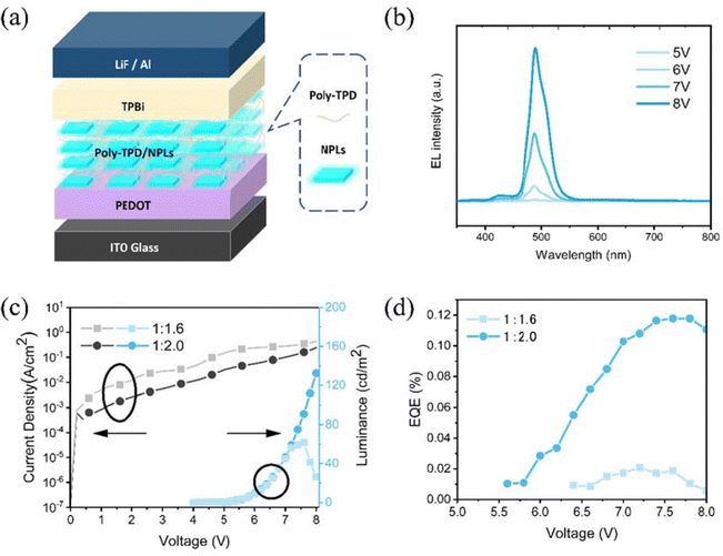
From these blade-coated films, PeNPLLED devices were fabricated utilizing a structure composed of indium tin oxide (ITO)/PEDOT: PSS (10 nm)/the nanocomposite film/TPBi (35 nm)/LiF (1 nm)/Al (100 nm), as shown in Fig. 7a. Fig. 7b shows the EL spectra of the optimized device (thickness 45 nm, solution concentration 15 mg mL−1 and NPLs-polymer ratio of 1![[thin space (1/6-em)]](https://www.rsc.org/images/entities/char_2009.gif) :
:![[thin space (1/6-em)]](https://www.rsc.org/images/entities/char_2009.gif) 2.0) under the forward bias of 5, 6, 7 and 8 V with the major EL peak located at 492 nm. Interestingly, the EL spectra show less emission from the polymer with respect to the PL spectra reported in Fig. 6a. We believe that this is determined by the recombination occurring directly in the NPLs due to electron and hole injection. The bad conductivity of poly-TBD for electrons gives rise to spurious recombination in the polymer.
2.0) under the forward bias of 5, 6, 7 and 8 V with the major EL peak located at 492 nm. Interestingly, the EL spectra show less emission from the polymer with respect to the PL spectra reported in Fig. 6a. We believe that this is determined by the recombination occurring directly in the NPLs due to electron and hole injection. The bad conductivity of poly-TBD for electrons gives rise to spurious recombination in the polymer.
LEDs made from suspensions of NPLs (15 mg mL−1): poly-TBD at 1![[thin space (1/6-em)]](https://www.rsc.org/images/entities/char_2009.gif) :
:![[thin space (1/6-em)]](https://www.rsc.org/images/entities/char_2009.gif) 1.6, and 1
1.6, and 1![[thin space (1/6-em)]](https://www.rsc.org/images/entities/char_2009.gif) :
:![[thin space (1/6-em)]](https://www.rsc.org/images/entities/char_2009.gif) 2.0 ratios were adjusted to a thickness of 45 nm. Fig. 7c shows the current density–voltage–luminance (J–V–L) curves of a device with an area of 16 mm2. The 1
2.0 ratios were adjusted to a thickness of 45 nm. Fig. 7c shows the current density–voltage–luminance (J–V–L) curves of a device with an area of 16 mm2. The 1![[thin space (1/6-em)]](https://www.rsc.org/images/entities/char_2009.gif) :
:![[thin space (1/6-em)]](https://www.rsc.org/images/entities/char_2009.gif) 1.6 device exhibited higher current density at low voltages compared to the other devices made from a higher amount of polymer (1
1.6 device exhibited higher current density at low voltages compared to the other devices made from a higher amount of polymer (1![[thin space (1/6-em)]](https://www.rsc.org/images/entities/char_2009.gif) :
:![[thin space (1/6-em)]](https://www.rsc.org/images/entities/char_2009.gif) 2.0), we believe that this difference is determined by some topographic defects in the active layer caused by the penetration of the cathode metal through the device stack. This device showed a maximum EQE of 0.02% and a maximum luminance of 61 cd m−2 (Fig. 7e and d), which further increased to maximum EQEs of 0.12% and a maximum luminance of 132 cd m−2 for the devices with a ratio of 1
2.0), we believe that this difference is determined by some topographic defects in the active layer caused by the penetration of the cathode metal through the device stack. This device showed a maximum EQE of 0.02% and a maximum luminance of 61 cd m−2 (Fig. 7e and d), which further increased to maximum EQEs of 0.12% and a maximum luminance of 132 cd m−2 for the devices with a ratio of 1![[thin space (1/6-em)]](https://www.rsc.org/images/entities/char_2009.gif) :
:![[thin space (1/6-em)]](https://www.rsc.org/images/entities/char_2009.gif) 2.0. The repeatability of the samples is rather good as shown by the statistics reported in the ESI,† Fig. S4. It is important also to note that the operational stability is limited to a few minutes. While the thin films are stable when stored in nitrogen.
2.0. The repeatability of the samples is rather good as shown by the statistics reported in the ESI,† Fig. S4. It is important also to note that the operational stability is limited to a few minutes. While the thin films are stable when stored in nitrogen.
It is important to underline that this is one of the first examples of a working perovskite NPL device. The difficulty of finding a suitable matrix for blending them, the presence of the ligands on its surface and the fact that the matrix, in this case, is conducting efficiently only holes are all serious limiting factors in achieving higher efficiency. Better results may be expected in the future, if the NPLs could be inserted in between a hole and electron transport layers of large bandgaps. However, such a device structure may pose several challenges in terms of processability.
3. Conclusions
In conclusion, we developed a nanoplatelet–perovskite–polymer composite film strategy for making uniform blade-coated thin films. The different blade-coating conditions were systematically studied, as well as the selection of polymers, the solution concentration, the ratio of NPL to polymer and the film thickness, to investigate their corresponding effect on the film formation. Our study revealed that using a high-concentration solution with an optimized NPL to polymer ratio at 1![[thin space (1/6-em)]](https://www.rsc.org/images/entities/char_2009.gif) :
:![[thin space (1/6-em)]](https://www.rsc.org/images/entities/char_2009.gif) 2 can be helpful for the suppression of phase separation and allow obtaining films of uniform surface morphology, which is a first pre-condition for the fabrication of LEDs. As a result, the optimized NPL-based LED shows a sharp emission peak at 492 nm with a peak EQE of 0.12% at 16 mm2 area. Our work highlights the important role of film morphology engineering through designing polymer composites and optimizing blade coating parameters to facilitate the large-scale application of perovskite NPLs in light-emitting solid-state devices.
2 can be helpful for the suppression of phase separation and allow obtaining films of uniform surface morphology, which is a first pre-condition for the fabrication of LEDs. As a result, the optimized NPL-based LED shows a sharp emission peak at 492 nm with a peak EQE of 0.12% at 16 mm2 area. Our work highlights the important role of film morphology engineering through designing polymer composites and optimizing blade coating parameters to facilitate the large-scale application of perovskite NPLs in light-emitting solid-state devices.
Data availability
Data are available upon request from the authors.Conflicts of interest
There are no conflicts to declare.Acknowledgements
The authors would like to express their gratitude for the technical assistance from Arjen Kamp and Teodor Zaharia. J. Chen appreciates financial funding from the Chinese Scholar Council (CSC). This work is funded by the European Union (ERC-AdvancedGrant, DEOM, 101055097). Views and opinions expressed are however those of the author(s) only and do not necessarily reflect those of the European Union or the European Research Council. Neither the European Union nor the granting authority can be held responsible for them.References
- C. Otero-Martínez, J. Ye, J. Sung, I. Pastoriza-Santos, J. Pérez-Juste, Z. Xia, A. Rao, R. L. Z. Hoye and L. Polavarapu, Adv. Mater., 2021, 2107105 Search PubMed.
- H. Wang, F. Ye, J. Sun, Z. Wang, C. Zhang, J. Qian, X. Zhang, W. C. H. Choy, X. W. Sun, K. Wang and W. Zhao, ACS Energy Lett., 2022, 1137–1145, DOI:10.1021/acsenergylett.1c02642,.
- L. Zhang, C. Sun, T. He, Y. Jiang, J. Wei, Y. Huang and M. Yuan, Light: Sci. Appl., 2021, 10, 61 CrossRef CAS PubMed.
- Y. Hassan, J. H. Park, M. L. Crawford, A. Sadhanala, J. Lee, J. C. Sadighian, E. Mosconi, R. Shivanna, E. Radicchi, M. Jeong, C. Yang, H. Choi, S. H. Park, M. H. Song, F. De Angelis, C. Y. Wong, R. H. Friend, B. R. Lee and H. J. Snaith, Nature, 2021, 591, 72–77 CrossRef CAS PubMed.
- Y. Dong, Y.-K. Wang, F. Yuan, A. Johnston, Y. Liu, D. Ma, M.-J. Choi, B. Chen, M. Chekini, S.-W. Baek, L. K. Sagar, J. Fan, Y. Hou, M. Wu, S. Lee, B. Sun, S. Hoogland, R. Quintero-Bermudez, H. Ebe, P. Todorovic, F. Dinic, P. Li, H. T. Kung, M. I. Saidaminov, E. Kumacheva, E. Spiecker, L.-S. Liao, O. Voznyy, Z.-H. Lu and E. H. Sargent, Nat. Nanotechnol., 2020, 15, 668–674 CrossRef CAS PubMed.
- H. Liu, M. Worku, A. Mondal, T. B. Shonde, M. Chaaban, A. Ben-Akacha, S. Lee, F. Gonzalez, O. Olasupo, X. Lin, J. S. R. Vellore Winfred, Y. Xin, E. Lochner and B. Ma, Adv. Energy Mater., 2022, 2201605 Search PubMed.
- C. Wang, D. Han, J. Wang, Y. Yang, X. Liu, S. Huang, X. Zhang, S. Chang, K. Wu and H. Zhong, Nat. Commun., 2020, 11, 6428 CrossRef CAS PubMed.
- Z. Li, Z. Chen, Y. Yang, Q. Xue, H.-L. Yip and Y. Cao, Nat. Commun., 2019, 10, 1027 CrossRef PubMed.
- Y. Wu, C. Wei, X. Li, Y. Li, S. Qiu, W. Shen, B. Cai, Z. Sun, D. Yang, Z. Deng and H. Zeng, ACS Energy Lett., 2018, 3, 2030–2037 CrossRef CAS.
- E.-P. Yao, Z. Yang, L. Meng, P. Sun, S. Dong, Y. Yang and Y. Yang, Adv. Mater., 2017, 29, 1606859 CrossRef PubMed.
- A. Q. Liu, C. H. Bi and J. J. Tian, Adv. Funct. Mater., 2022, 32(44), 2207069, DOI:10.1002/adfm.202207069.
- Y. Bekenstein, B. A. Koscher, S. W. Eaton, P. Yang and A. P. Alivisatos, J. Am. Chem. Soc., 2015, 137, 16008–16011 CrossRef CAS PubMed.
- B. J. Bohn, Y. Tong, M. Gramlich, M. L. Lai, M. Döblinger, K. Wang, R. L. Z. Hoye, P. Müller-Buschbaum, S. D. Stranks, A. S. Urban, L. Polavarapu and J. Feldmann, Nano Lett., 2018, 18, 5231–5238 CrossRef CAS PubMed.
- Y. Shynkarenko, M. I. Bodnarchuk, C. Bernasconi, Y. Berezovska, V. Verteletskyi, S. T. Ochsenbein and M. V. Kovalenko, ACS Energy Lett., 2019, 4, 2703–2711 CrossRef CAS PubMed.
- M. J. Rivera Medina, L. Di Mario, S. Kahmann, J. Xi, G. Portale, G. Bongiovanni, A. Mura, J. C. Alonso Huitrón and M. A. Loi, Nanoscale, 2023, 15, 6673–6685 RSC.
- J. Xing, Y. Zhao, M. Askerka, L. N. Quan, X. Gong, W. Zhao, J. Zhao, H. Tan, G. Long, L. Gao, Z. Yang, O. Voznyy, J. Tang, Z.-H. Lu, Q. Xiong and E. H. Sargent, Nat. Commun., 2018, 9, 3541 CrossRef PubMed.
- J. Hu, I. W. H. Ostwald, S. J. Stuard, M. M. Nahid, N. Zhou, O. F. Williams, Z. Guo, L. Yan, H. Hu, Z. Chen, X. Xiao, Y. Lin, Z. Yang, J. Huang, A. M. Moran, H. Ade, J. R. Neilson and W. You, Nat. Commun., 2019, 10, 1276 CrossRef PubMed.
- W. Shen, Y. Yu, W. Zhang, Y. Chen, J. Zhang, L. Yang, J. Feng, G. Cheng, L. Liu and S. Chen, ACS Appl. Mater. Interfaces, 2022, 14, 5682–5691 CrossRef CAS PubMed.
- C. Zhao, P. Liu, W. Cai, W. Xu, M. U. Ali, Z. Xu, H. Y. Fu, H. Meng, J. Li and G. Wei, Adv. Mater. Interfaces, 2022, 2102212 CrossRef CAS.
- W. Feng, Y. Zhao, K. Lin, J. Lu, Y. Liang, K. Liu, L. Xie, C. Tian, T. Lyu and Z. Wei, Adv. Funct. Mater., 2022, 2203371 CrossRef CAS.
- Y. Xin, H. Zhao and J. Zhang, ACS Appl. Mater. Interfaces, 2018, 10, 4971–4980 CrossRef CAS PubMed.
- T. Xuan, J. Huang, H. Liu, S. Lou, L. Cao, W. Gan, R.-S. Liu and J. Wang, Chem. Mater., 2019, 31, 1042–1047 CrossRef CAS.
- H. Wu, S. Wang, F. Cao, J. Zhou, Q. Wu, H. Wang, X. Li, L. Yin and X. Yang, Chem. Mater., 2019, 31, 1936–1940 CrossRef CAS.
- R. L. Z. Hoye, M.-L. Lai, M. Anaya, Y. Tong, K. Gałkowski, T. Doherty, W. Li, T. N. Huq, S. Mackowski, L. Polavarapu, J. Feldmann, J. L. MacManus-Driscoll, R. H. Friend, A. S. Urban and S. D. Stranks, ACS Energy Lett., 2019, 4, 1181–1188 CrossRef CAS PubMed.
- C. Bi, S. Wang, S. V. Kershaw, K. Zheng, T. Pullerits, S. Gaponenko, J. Tian and A. L. Rogach, Adv. Sci., 2019, 6, 1900462 CrossRef PubMed.
- Y. Ling, Z. Yuan, Y. Tian, X. Wang, J. C. Wang, Y. Xin, K. Hanson, B. Ma and H. Gao, Adv. Mater., 2016, 28, 305–311 CrossRef CAS PubMed.
- D. Liang, Y. Peng, Y. Fu, M. J. Shearer, J. Zhang, J. Zhai, Y. Zhang, R. J. Hamers, T. L. Andrew and S. Jin, ACS Nano, 2016, 10, 6897–6904 CrossRef CAS PubMed.
- Z. Zhang, J. Shang, H. Ge, Y. Zhang, L. Zhou, W. Zhu, D. Chen, J. Zhang, C. Zhang and Y. Hao, Mater. Today Energy, 2023, 36, 101343 CrossRef CAS.
- K. Wang and L. Dou, Nat. Nanotechnol., 2022, 17, 562–563 CrossRef CAS PubMed.
- Y.-H. Kim, J. Park, S. Kim, J. S. Kim, H. Xu, S.-H. Jeong, B. Hu and T.-W. Lee, Nat. Nanotechnol., 2022, 17(6), 590–597, DOI:10.1038/s41565-022-01113-4.
- M. Remeika and Y. Qi, J. Energy Chem., 2018, 27, 1101–1110 CrossRef.
- S. Chu, Y. Zhang, P. Xiao, W. Chen, R. Tang, Y. Shao, T. Chen, X. Zhang, F. Liu and Z. Xiao, Adv. Mater., 2022, 34, 2108939 CrossRef CAS PubMed.
- H. Zhu, M. Cheng, J. Li, S. Yang, X. Tao, Y. Yu and Y. Jiang, Chem. Eng. J., 2022, 428, 130974 CrossRef CAS.
- K. Hoshi, T. Chiba, J. Sato, Y. Hayashi, Y. Takahashi, H. Ebe, S. Ohisa and J. Kido, ACS Appl. Mater. Interfaces, 2018, 10, 24607–24612 CrossRef CAS PubMed.
- Y. Ling, Y. Tian, X. Wang, J. C. Wang, J. M. Knox, F. Perez-Orive, Y. Du, L. Tan, K. Hanson, B. Ma and H. Gao, Adv. Mater., 2016, 28, 8983–8989 CrossRef CAS PubMed.
- Q. Zhou, Z. Bai, W.-G. Lu, Y. Wang, B. Zou and H. Zhong, Adv. Mater., 2016, 28, 9163–9168 CrossRef CAS PubMed.
- S. G. R. Bade, X. Shan, P. T. Hoang, J. Li, T. Geske, L. Cai, Q. Pei, C. Wang and Z. Yu, Adv. Mater., 2017, 29, 1607053 CrossRef PubMed.
- M. Vasilopoulou, A. Fakharuddin, F. P. García de Arquer, D. G. Georgiadou, H. Kim, A. R. B. Mohd Yusoff, F. Gao, M. K. Nazeeruddin, H. J. Bolink and E. H. Sargent, Nat. Photonics, 2021, 15, 656–669 CrossRef CAS.
- G. Nedelcu, ETH Zurich, 2019 DOI:10.3929/ethz-b-000369809.
- J. A. Sichert, Y. Tong, N. Mutz, M. Vollmer, S. Fischer, K. Z. Milowska, R. García Cortadella, B. Nickel, C. Cardenas-Daw, J. K. Stolarczyk, A. S. Urban and J. Feldmann, Nano Lett., 2015, 15, 6521–6527 CrossRef CAS PubMed.
- S. Peng, S. Wang, D. Zhao, X. Li, C. Liang, J. Xia, T. Zhang, G. Xing and Z. Tang, Small Methods, 2019, 3, 1900196 CrossRef CAS.
- Z. L. Tseng, L. C. Chen, L. W. Chao, M. J. Tsai, D. A. Luo, N. R. Al Amin, S. W. Liu and K. T. Wong, Adv. Mater., 2022, 34(18), 2109785 CrossRef CAS PubMed.
- Y. Zhong, R. Munir, J. Li, M.-C. Tang, M. R. Niazi, D.-M. Smilgies, K. Zhao and A. Amassian, ACS Energy Lett., 2018, 3, 1078–1085 CrossRef CAS.
- Z.-K. Tan, R. S. Moghaddam, M. L. Lai, P. Docampo, R. Higler, F. Deschler, M. Price, A. Sadhanala, L. M. Pazos, D. Credgington, F. Hanusch, T. Bein, H. J. Snaith and R. H. Friend, Nat. Nanotechnol., 2014, 9, 687–692 CrossRef CAS PubMed.
Footnote |
| † Electronic supplementary information (ESI) available. See DOI: https://doi.org/10.1039/d4tc02404d |
| This journal is © The Royal Society of Chemistry 2024 |

