 Open Access Article
Advances in electrochemical energy storage with covalent organic frameworks†
Vikram
Singh
 *abc and
Hye Ryung
Byon
 *ab
*ab
aDepartment of Chemistry, Korea Advanced Institute of Science and Technology (KAIST), 291 Daehak-ro, Yuseong-gu, Daejeon 34141, Republic of Korea. E-mail: hrbyon@kaist.ac.kr; vsingh@kaist.ac.kr
bAdvanced Battery Centre, KAIST Institute for NanoCentury, Daejeon 34141, Republic of Korea
cNational Science Research Centre, Korea Advanced Institute of Science and Technology (KAIST), 291 Daehak-ro, Yuseong-gu, Daejeon 34141, Republic of Korea
First published on 19th April 2021
Abstract
The use of all-organic materials for electrochemical energy storage holds great promise for the development of foldable cellphones, lightweight computers, stretchable patch-type electronic devices, and other technologically advanced applications. Thus, the development of stable, scalable, and inexpensive electroactive organic materials has been extensively investigated. Covalent organic frameworks (COFs) are attractive candidates for two- and three-dimensional integration of small organic molecules. They offer regular-sized pore channels, a rich diversity of the desired chemical motifs, and feasible designs of chemical and bulk structure through the availability of various synthetic approaches. In this review, we highlight the recent studies in the design of COFs for rechargeable metal-ion batteries, (pseudo)capacitors, ion conductors, and solid-state electrolytes. We also discuss the advantages and challenges of future COF design to satisfy the criteria of industrial production.
Introduction
The ongoing development of electronic devices and efforts aiming to reduce our dependence on fossil fuels have increased the demand for electrochemical energy storage techniques.1–3 In particular, energy density defining the operation time per charging process should be significantly ameliorated with the drastic development of cutting-edge technologies ranging from portable electronics to electric vehicles.4,5 In addition, versatile energy storage concepts are vital to utilize both traditionally rigid and robust devices as well as lightweight, flexible, and foldable electronics (e.g., foldable cellphones, flimsy computers, and stretchable patch-type electronic devices).6,7 Given the broad application scope of these devices, diverse up-to-date electronics are expected to become ubiquitous in the near future, which highlights the need for new types of batteries and capacitors.1,8,9 As conventional inorganic compound-based materials are not suitable for such devices, much effort has been directed at the development of reasonably cheap all-organic-molecule batteries with performances similar to those of their inorganic material-based counterparts.10–13In an organic electrode, redox-active organic motifs interact with charge carriers and should be integrated with low-density organic frameworks that help to establish the overall electrode structure, prevent dissolution, and provide electron- and ion-transport channels.14–18 Deep knowledge of molecular engineering and conglomeration allows for tunable structural design and electrochemical characteristic adjustment.14,16,19 For example, much attention has been directed at the fabrication of organic electrodes and solid electrolytes from polymers.17,20,21 However, irregular frameworks comprising polymeric layers may not provide channels for efficient electron and ion transport, and their currently unimpressive performance is ascribed to the lack of periodic porosity and poor electronic conductivity.15,22
Covalent organic frameworks (COFs) are promising electrode materials with metal-free crystalline organic structures. Organic building blocks are regularly integrated through covalent bonds to afford two-dimensional (2D) porous sheets. These organic sheets are stacked via π–π interactions to establish a three-dimensional (3D) framework. Pores create porous channels and provide a high surface area and low density. Yaghi's group first used reticular chemistry to fabricate 2D and 3D COFs featuring organic building blocks linked by boronate ester and/or boroxine units.23,24 These organic frameworks had long-range order and formed a polycrystalline network owing to the partial reversibility of covalent bond formation in the condensation reaction, a phenomenon termed as dynamic covalent chemistry.25–33 Typically, COFs have higher synthetic flexibility than porous organic polymers and zeolites while exhibiting higher stability than metal–organic frameworks. Therefore, these organic structures are highly promising for the fabrication of electrodes and electrolytes for electrochemical energy storage.
Herein, we review the design of COF chemical moieties and structures for capacitors, batteries, and ionic conductors/solid electrolyte applications. Many studies on multiple synthetic methods and functions of chemical groups that are periodically combined constitute a COF library. This compiling knowledge underscores the importance of structural aspects, including π-conjugation in both in-plane and out-of-plane directions, pore engineering, crystallinity, and symmetrical motifs. COF structure is determined by molecular interactions such as strong covalent bonding between organic building blocks. In addition, the desired chemical moieties integrated into the building blocks should communicate with charge carriers in the target system through electrostatic interactions, dipole–dipole interactions, hydrogen bonds, or ionic bonds. All of these components should be stable toward acids, bases, oxidants, reductants, and electrochemical environments. As the design of COFs should primarily target their electrochemical energy storage applications, this review presents various trials and errors for each application to ameliorate cell performance and reveals that such libraries facilitate the fabrication of better and more versatile organic materials for energy storage. Numerous studies have focused on the role of linkages, pore size, symmetry, interlayer interactions, electronic structure, and in-plane/out-of-plane conductivity of COFs, revealing the current challenges and future prospects for electrochemical energy storage.
Design and characterization of electroactive COFs
Design of COF active materials
COFs comprise periodically arranged organic units, and the role and performance of COFs as active materials for electrochemical energy storage are determined by the organic species serving as linkages and chemical functionalities. Favorable combinations of organic material properties such as polarity, electrostatic charge, electron delocalization, rigidity, and flexibility offer cooperative characteristics that can be tuned depending on target applications.COFs comprise both electroactive and -inactive organic species, which act as electrochemical reactors and rigid skeletons, respectively. Quinones, imides, carboxylates (C![[double bond, length as m-dash]](https://www.rsc.org/images/entities/char_e001.gif) O), imines (C
O), imines (C![[double bond, length as m-dash]](https://www.rsc.org/images/entities/char_e001.gif) N), azo compounds (N
N), azo compounds (N![[double bond, length as m-dash]](https://www.rsc.org/images/entities/char_e001.gif) N), pyridines, phenazines, and triazines are often used as electroactive units suitable for the implementation of both faradaic and non-faradaic processes. These active moieties are introduced into COFs through pre- or post-functionalization. In addition, the introduction of ionic (e.g., imidazolate and sulfonic acid) groups and hydrophobic/hydrophilic (e.g., perfluoroalkyl, polyethylene glycol, and polyethylene oxide) groups increases the mobility of charge carriers through the long porous COF channels, making them useful as ion conductors and solid-state electrolytes.34
N), pyridines, phenazines, and triazines are often used as electroactive units suitable for the implementation of both faradaic and non-faradaic processes. These active moieties are introduced into COFs through pre- or post-functionalization. In addition, the introduction of ionic (e.g., imidazolate and sulfonic acid) groups and hydrophobic/hydrophilic (e.g., perfluoroalkyl, polyethylene glycol, and polyethylene oxide) groups increases the mobility of charge carriers through the long porous COF channels, making them useful as ion conductors and solid-state electrolytes.34
The COF skeleton is established using linkage chemistry, with the linker size and symmetry determining the pore size, pore volume, and 3D stacking structure (Table S1, ESI†).26 In bulk COFs, the pores are connected to form nanoporous channels (diameter = 1–6 nm, length = several microns) that enable the transport of ions and electrolyte solutions. The grafting of polar moieties along pore walls enhances wetting and promotes the access of charge carriers to COF redox-active moieties. Control over the COF structure thickness may also allow one to alter wettability. In particular, thin COF films directly synthesized on conductive carbons (e.g., carbon nanotubes and graphene) or formed by exfoliation of bulk COFs via chemical or mechanical methods have been extensively employed to enhance wettability and increase electronic conductivity. The imine and β-ketoenamine moieties widely used in linkage chemistry are often unstable under electrochemical and chemical operating conditions. Specifically, at high pH the imine group is prone to hydrolysis and induces interlayer repulsions in the COF structure,35,36 whereas the β-ketoenamine group suffers from electron delocalization deficiency and may not be an ideal choice under the stringent electrochemical conditions required for molecular redox chemistry.37 Therefore, optimum linkage choice is crucial to avoid COF skeleton degradation.
General characterization of COFs
COF crystals are synthesized using various (e.g., solvothermal, ionothermal, microwave, microfluidic, and mechanochemical) methods38–41 under diverse temperature42 and reaction time conditions.40,43 Subsequently, the residuals (reaction/washing solvents and pore-attached impurities) in pores are removed by heating at high temperatures (100–200 °C) and very low pressures (∼10−5 torr) for >12 h. COFs are generally obtained as powders that are insoluble in both aqueous and non-aqueous solvents28 and are analyzed by solid-state characterization techniques to determine chemical functionality, purity, and crystallinity.Infrared and nuclear magnetic resonance (NMR) spectroscopies are commonly used to probe the functional groups in COFs and confirm the negligible content of residuals,44 whereas the thermal stability of COFs in O2 or N2 environments is probed by thermogravimetric analysis. In general, COFs should be stable up to 350 °C under N2. COF crystallinity can be confirmed by powder X-ray diffraction (PXRD). The PXRD patterns of many COFs feature very intense peaks at low angles (<5°), which can be used to determine the degree of crystallinity. Moreover, the peak at ∼27° indicates a π–π stacked layer structure if weak but reflects poor stacking interactions when broad and intense. The presence of small organic groups tethered to COFs does not generally change the overall framework geometry. Simulated PXRD patterns can be compared with experimental ones using Rietveld, Pawley, and other refinement methods to identify the true COF crystal structure. Strong π–π interlayer interactions typically favor an eclipsed structure, whereas several COFs have been reported to feature staggered and stair-cased structures.45–48 Grazing incidence X-ray diffraction has been used to identify the vertical orientation of COF stacks relative to the substrate and determine film crystallinity.49 The porosity of residual-free COFs can be determined from their N2 adsorption–desorption isotherms recorded at 77 K, which are commonly of type IV and indicate microporosity as well as significant N2 uptake at low pressures. The obtained isotherms can be used to calculate surface areas, pore sizes, and pore volumes using Brunauer–Emmett–Teller (BET; SBET) and Barrett–Joyner–Halenda (SBJH) methods. Microscopic imaging sheds light on COF morphology and thickness and is typically performed using scanning electron microscopy and transmission electron microscopy.50 In the case of COF thin films or exfoliated COF layers, atomic force microscopy is employed for deciphering film thickness.51,52 Scanning tunneling microscopy (STM) supplies atomic-resolution images of the crystal lattice and its defects as well as provides information on electronic structure.53 For instance, Feyter group used STM to demonstrate a localized reversible transformation of supramolecular networks to COFs.54,55
COF electrode preparation and COF conductivity enhancement
Preparation of COF electrodes
Typically, electrodes are prepared by mixing the COF, conductive carbon (e.g., Super P and acetylene black), and a binder (e.g., poly(vinylidene fluoride)). For battery applications, the COF (i.e., active material) should account for >70 wt% of the electrode mass. The above three components are blended using a solvent (e.g., N-methyl pyrrolidone, and water), and the resulting slurry is deposited on metallic substrates through drop-casting or doctor-blading. The complete electrodes are dried under vacuum or in ambient air at a suitable temperature.In the case of sulfur batteries, where COFs serve as the host material to confine elemental sulfur, the COF and sulfur are ground, placed inside a sealed container, and annealed at 150–200 °C for several hours to achieve the impregnation of sulfur into the porous channels of the COF.
In the case of ionic conductors, the ground COFs are pressed using a pellet maker and sandwiched between conducting substrates such as Ti, Li, and Cu using cold-pressing or oil-pressing for impedance measurements.
Enhancement of COF conductivity
The nanoporous channels in the vertically aligned structure of COFs can serve as ionic channels and provide high pore volume and excellent surface area. However, tens of micron-scale ionic channels retard wetting inside the bulk COF. In addition, strong interlayer interactions in the COF structure may hinder the access of charge carriers to the active moieties or the interlayers. From an electronic point of view, organic materials typically have low conductivity unless electron-delocalized π-conjugation is established in the in-plane of COF. The electron/ion transport in the vertical direction, that is, in the out-of-plane direction, should also be reasonably rapid to enable fast charging.Three key strategies have been developed to increase COF conductivity (Fig. 1). In the first method, ion diffusion length is decreased using few-layer covalent organic nanosheets (CONs), which are either prepared by COF exfoliation or synthesized directly, as discussed in detail by Zamora's and Tang's groups.30,56 Briefly, the exfoliation approach can be realized through liquid-phase or mechanical exfoliation, with the former commonly performed by sonication (to weaken interlayer interactions)57 and chemical (stereo-controlled (e.g., Diels–Alder) reactions,58 introduction of charged (e.g., guanidinium) linkers,59 or the use of self-exfoliating (e.g., triazole functionalities)51 techniques. Mechanical exfoliation can be achieved through the mechano-assisted synthesis or mechanical grinding of bulk COFs using a pestle/mortar or ball milling.60 However, the decrease in lateral dimensions due to such top-down exfoliation can deteriorate crystallinity. Alternatively, CONs can be fabricated directly from monomer precursors via on-surface or interfacial synthesis. For on-surface synthesis, monomers are deposited on ultraclean oriented substrates (e.g., SiO2, Au(111), Ag(111), and highly oriented pyrolytic graphite) under solvent-free and ultra-high-vacuum (UHV) conditions at high temperatures.30 Moreover, on-surface synthesis can be realized via the drop-casting of monomers onto the desired substrate. As covalent bonds can be formed in the equilibrium state of a chemical reaction, liquid-assisted synthesis is superior to UHV-condition synthesis, affording CONs with fewer defects and higher crystallinity on a long-range order of 200 × 200 nm2 to 1 μm2.49,61 Interfacial synthesis utilizes monomer reactions at air–liquid or liquid–liquid interfaces using immiscible solvents and affords films that are suspended at the interface and can be easily transferred to the substrate. The advantage of this method is the precise control of film thickness through repeated transfer. Considering the COF–electrode interaction, thin CON deposition/growth on carbon nanotubes (CNTs) or graphene can enhance electron transport. Moreover, the conjugated nature of CONs and CNTs/graphene results in strong π–π interactions.
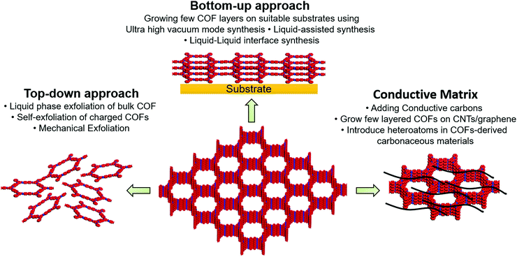 | ||
| Fig. 1 Depiction of three key strategies to improve intrinsic and extrinsic conductivity of covalent organic frameworks. | ||
Although the Li+ diffusion length decreases with decreasing COF structure thickness, which generally results in increased electrical conductivity, the COF content is concomitantly reduced. As an active material (COF) loading of >70 wt% is required for batteries, we believe that the optimization of porous channels is a better strategy.
Capacitors
Capacitors are generally operated through the physisorption of charge carriers, mostly ions, at the electrified interface. This capacitive process, giving rise to the so-called electrochemical double-layer capacitance (EDLC), is fast and does not involve chemical reactions.62 Typically, such supercapacitors have seamless carbon electrodes and should have a high surface area and a large pore volume to exhibit a sufficiently high EDLC. The physical events in capacitors takes advantage of the high power density and high stability toward long-term cycling in a wide temperature range. In comparison, the doping of carbon electrodes with heteroatoms such as oxygen and nitrogen preferentially improves wettability and provides sites for faradaic chemical adsorption (giving rise to pseudo-capacitance) in aqueous electrolyte solutions. Although pseudo-capacitive behavior accounts for a small portion of the overall capacitance, its contribution is significant. Thus, to improve capacitance, one should achieve a high surface area, pore volume, and chemical modification with various moieties.Electrochemical characterizations are typically performed by cyclic voltammetry (CV) in a three-electrode setup, with the rectangular shape of the CV curve attributed to EDLC. The appearance of redox waves in the rectangular profile indicates the contribution of a pseudo-capacitive process. This interfacial event is determined not only by the electrode, but also by the electrolyte. Compared to other ions (Na+, K+, and ionic liquid components), protons (H+) have the largest mobility and ability to enhance the faradaic events involving the heteroatoms of the carbon electrode. The corresponding performance can be evaluated by galvanostatic charge–discharge cycling. Although three-electrode cells are often used for such cycling, the evaluation of practical electrochemical capacitors and hybrid ion capacitors should ideally be performed using two-electrode full cells.63
Pseudo-capacitors
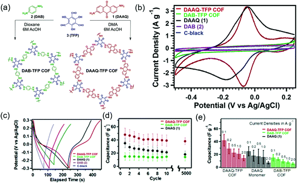
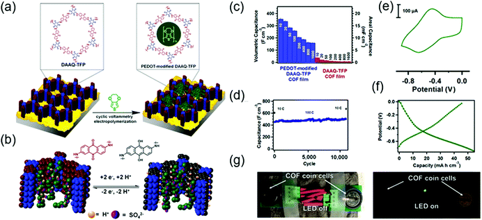
The first demonstration of a COF-based pseudo-capacitor was achieved by the Dichtel group in 2013, who designed 2,6-diaminoanthraquinone (DAAQ)-linked 1,3,5-triformylphloroglucinol (Tp) to form a β-ketoenamine linked DAAQ-Tp COF (Fig. 2).64 This COF had a surface area (SBET) of ∼1800 m2 g−1 and exhibited high chemical stability under acidic conditions. In a three-electrode setup, the DAAQ-Tp COF electrode showed a voltage plateau at −0.05 V vs. Ag/AgCl in 1.0 M H2SO4(aq) and delivered a capacitance of 40 ± 9 F g−1 at 0.1 A g−1 over 5000 galvanostatic cycles. However, the utilization extent of the anthraquinone redox moiety was low (2.5%) and, hence, the accessibility of H+ adsorption to anthraquinone, were low. As a control experiment, the researchers tested a diaminobenzene-based DAB-Tp COF that did not have redox-active sites. The obtained rectangular CV curve and the shark-fin-shaped galvanostatic curve allowed the contribution of EDLC to be estimated as 15 ± 6 F g−1. Lei's group grew a multilayer COF on a 3D graphene aerogel to improve the electronic conductivity and participation of anthraquinone in the pseudocapacitive process. The imine-linked anthraquinone COF was synthesized via the condensation of DAAQ with benzene-1,3,5-tricarbaldehyde (BTA) on graphene layers and was denoted as DAAQ–BTA, with the COF mass loading and thickness equaling 0.253 mg cm−2 and 180 nm, respectively.65 Under alkaline conditions (1.0 M KOH(aq)), three-electrode cells with DAAQ–BTA exhibited a formal redox potential (E0′) of −0.85 V vs. Ag/AgCl. Galvanostatic tests showed that the degree of anthraquinone utilization was close to 13.5% at a current density of 0.025 mA cm−2. However, after 500 cycles at 0.5 mA cm−2, capacitance rapidly decayed to 30% of the initial value (31.7 mF cm−2). Notably, the DAAQ monomer incompletely reacted with BTA during synthesis or remained trapped in COF pores, which was indicative of amorphous structure of the COF. Thus, the above COF was concluded to undergo decomposition and dissolution during cycling.The Dichtel group further investigated the structural orientation of DAAQ-Tp COF in electrodes and its effect on capacitor performance (Fig. 3). In particular, a thin-film DAAQ-Tp COF (thickness = 60–560 nm) was deposited on Au substrates.49,66 The significant (001) peak observed in the grazing-incidence X-ray diffraction pattern of this film indicated the predominantly vertical orientation of the COF with respect to the substrate. When 0.1 M TBAPF6/CH3CN was employed as the electrolyte, the utilization extent of anthraquinone increased with decreasing initial concentration of DAAQ and COF thickness, e.g., 250 nm-thick COF films attained an areal capacitance of 3.0 mF cm−2 at 0.15 mA cm−2. In addition, a capacitance loss of only ∼7% was observed after 5000 galvanostatic cycles. In comparison, the capacitance of a powder COF electrode approached 0.40 mF cm−2, i.e., was 7.5 times lower than that of the above thin-film electrode. Nonetheless, such thin-film electrodes cannot sustain high current densities, which significantly reduces power density. To tackle this limitation, Dichtel group introduced a conducting polymer, poly(3,4-ethylenedioxythiophene) (PEDOT), into the nanopores of DAAQ-Tp COF through electropolymerization (Fig. 4).67 A 1 μm-thick DAAQ-Tp/PEDOT film delivered a charge storage of 9.3 mC in 0.5 M H2SO4(aq), which was more than 40 times higher than that of the PEDOT-free DAAQ-Tp COF. The three-electrode cells demonstrated a high charging rate of up to 1600C, retaining 50% of the maximum capacitance (600 F cm−3). In addition, a capacitance of 450 F cm−3 was maintained at 100C for 10![[thin space (1/6-em)]](https://www.rsc.org/images/entities/char_2009.gif) 000 galvanostatic cycles. Two-electrode cells assembled with porous carbon electrodes displayed a charging rate of up to 800C.
000 galvanostatic cycles. Two-electrode cells assembled with porous carbon electrodes displayed a charging rate of up to 800C.
One of the advantages of organic electrodes is their ability to mechanically sustain flexible electrodes and capacitors. Banerjee's group used a DAAQ-Tp COF with variable contents of a π-electron-rich anthracene (Da),68 showing that enhanced non-covalent interactions between COF layers increased electrode flexibility. The pure Da-Tp COF (i.e., that without DAAQ units) displayed the best mechanical robustness, showing a breaking strain of 9%, which exceeded that of the more fragile DAAQ-only COF (2%). Flexible electrodes were prepared with a 1![[thin space (1/6-em)]](https://www.rsc.org/images/entities/char_2009.gif) :
:![[thin space (1/6-em)]](https://www.rsc.org/images/entities/char_2009.gif) 1 molar ratio of DAAQ and Da, namely the DAAQ1Da1Tp COF film, which was adhered to a graphite substrate using conductive carbon tape. These COF films (thickness = 25–100 μm) displayed a geometric area of 15 cm2,68 while an aerial capacitance of 8.5 mF cm−2 was observed at 0.39 mA cm−2. While the DAAQ1Da1Tp COF achieved a 90% capacitance retention over 2500 galvanostatic cycles owing to its favorable redox and mechanical properties, the DAAQ-Tp COF showed capacitance retention of only 80% under the same conditions.
1 molar ratio of DAAQ and Da, namely the DAAQ1Da1Tp COF film, which was adhered to a graphite substrate using conductive carbon tape. These COF films (thickness = 25–100 μm) displayed a geometric area of 15 cm2,68 while an aerial capacitance of 8.5 mF cm−2 was observed at 0.39 mA cm−2. While the DAAQ1Da1Tp COF achieved a 90% capacitance retention over 2500 galvanostatic cycles owing to its favorable redox and mechanical properties, the DAAQ-Tp COF showed capacitance retention of only 80% under the same conditions.
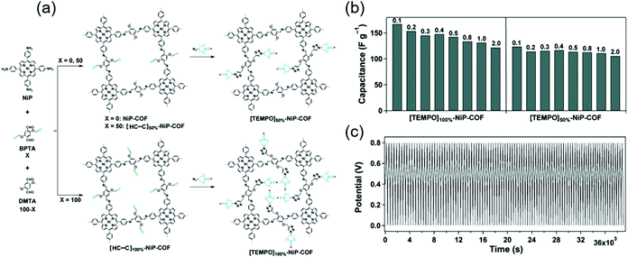
Jiang's group covalently linked a stable redox-active organic radical, 4-azido-2,2,6,6-tetramethyl-1-piperidinyloxy (TEMPO), to the porous walls of nickel-porphyrin COFs (NiP COF) to afford a new redox core (Fig. 5).69 NiP COFs with ethynyl group contents of 50 and 100% were functionalized with TEMPO through click chemistry, and the obtained products were named as [TEMPO]50%-NiP and [TEMPO]100%-NiP, respectively. The SBET of the latter COF (5.2 m2 g−1) was much less than that of the non-functionalized parent COF (1219 m2 g−1), indicating the dense loading of TEMPO in [TEMPO]100%-NiP. In a three-electrode cell with 0.1 M TBAClO4/CH3CN, the capacitances of [TEMPO]100%-NiP and [TEMPO]50%-NiP were determined as 113 and 101 F g−1 at 2 A g−1, respectively. Thus, both TEMPO-functionalized COFs featured comparable capacitances, and [TEMPO]50%-NiP additionally provided stable cyclability.
Tang's group utilized a pyridine (Py)-linked β-ketoenamine to create a TpPa-Py COF.70 The two redox waves observed at −0.3 and 0.4 V vs. Ag/AgCl in 1.0 M H2SO4(aq) were ascribed to the reduction of Py units to afford a pyridinyl radical and then dihydropyridine. Capacitances of 209 and 164 F g−1 were determined at 0.5 and 5.0 A g−1, respectively. According to CV measurements performed at a scan rate of 1 mV s−1, the Py unit was utilized to 2.7%. Galvanostatic cyclability tests showed that only ∼8% of capacitance was lost after 6000 cycles at 2 A g−1. The monomer diaminopyridine provided only 47 F g−1 at 0.5 A g−1, which underscores the role of COFs in hindering the dissolution of redox-active molecules. A triazine-based COF (TDFP-1) reported by Bhaumick's group71 achieved a maximum specific capacitance of 354 F![[thin space (1/6-em)]](https://www.rsc.org/images/entities/char_2009.gif) g−1 at a CV scan rate of 2 mV
g−1 at a CV scan rate of 2 mV![[thin space (1/6-em)]](https://www.rsc.org/images/entities/char_2009.gif) s−1 in a conventional three-electrode setup with 0.1 M H2SO4(aq). In addition, a capacitance retention of ∼95% was achieved after 1000 cycles at 10 A
s−1 in a conventional three-electrode setup with 0.1 M H2SO4(aq). In addition, a capacitance retention of ∼95% was achieved after 1000 cycles at 10 A![[thin space (1/6-em)]](https://www.rsc.org/images/entities/char_2009.gif) g−1. This superior performance was ascribed to the high surface area (651 m2 g−1) of TDFP-1.
g−1. This superior performance was ascribed to the high surface area (651 m2 g−1) of TDFP-1.
Banerjee's group focused on the role of interlayer hydrogen bonding in COFs for capacitor applications37,72 and synthesized a hydroquinone-based COF with β-ketoenamine linkage (TpPa-(OH)2).72 In a three-electrode setup with 1.0 M phosphate buffer (pH = 7.2), capacitances of 211 and 416 F g−1 were obtained at a CV scan rate of 2 mV s−1 and a galvanostatic current density of 0.5 A g−1, respectively. Both of the above values exceeded that of the aforementioned thin-film DAAQ-Tp COF and were ascribed to the benzoquinone/hydroquinone redox event in the pH range of 3.6–7.2. In addition, a capacitance retention of 66% was obtained after 10![[thin space (1/6-em)]](https://www.rsc.org/images/entities/char_2009.gif) 000 galvanostatic cycles at 5 A g−1. This highly stable cell performance was ascribed to hydrogen bonding between the carbonyl oxygen (C
000 galvanostatic cycles at 5 A g−1. This highly stable cell performance was ascribed to hydrogen bonding between the carbonyl oxygen (C![[double bond, length as m-dash]](https://www.rsc.org/images/entities/char_e001.gif) O) of benzoquinone and the secondary N atom of the β-ketoenamine linkage. The above researchers also prepared a hydrogen bond–free phenolic group-based COF, TpBD-(OH)2, for comparison, achieving a capacitance of 86 F g−1 at a CV scan rate of 2 mV s−1 and a capacitance retention of 2% after 1000 cycles. This poor performance was attributed to the formation of unstable phenoxy radicals during reduction. In contrast, when the DAAQ COF was modified with both imine linkage and methoxy (OMe) functional groups to afford TpOMe-DAAQ,37 the C
O) of benzoquinone and the secondary N atom of the β-ketoenamine linkage. The above researchers also prepared a hydrogen bond–free phenolic group-based COF, TpBD-(OH)2, for comparison, achieving a capacitance of 86 F g−1 at a CV scan rate of 2 mV s−1 and a capacitance retention of 2% after 1000 cycles. This poor performance was attributed to the formation of unstable phenoxy radicals during reduction. In contrast, when the DAAQ COF was modified with both imine linkage and methoxy (OMe) functional groups to afford TpOMe-DAAQ,37 the C![[double bond, length as m-dash]](https://www.rsc.org/images/entities/char_e001.gif) N groups of the imine linkage, which repelled each other through interlayers, were stabilized by forming interlayer hydrogen bonds with the OMe group (C–H⋯NH–). Self-standing 200 μm-thick TpOMe-DAAQ COF films in three-electrode cells delivered capacities of 1600 mF cm−2 (or 169 F g−1) at 3.3 mA cm−2. Galvanostatic cycling revealed high stability, showing a negligible capacitance loss for up to 100
N groups of the imine linkage, which repelled each other through interlayers, were stabilized by forming interlayer hydrogen bonds with the OMe group (C–H⋯NH–). Self-standing 200 μm-thick TpOMe-DAAQ COF films in three-electrode cells delivered capacities of 1600 mF cm−2 (or 169 F g−1) at 3.3 mA cm−2. Galvanostatic cycling revealed high stability, showing a negligible capacitance loss for up to 100![[thin space (1/6-em)]](https://www.rsc.org/images/entities/char_2009.gif) 000 cycles at 10 mA cm−2. Vaidyanathan group employed triazine and Py as redox-active moieties and prepared imine-linked triazine-Py COFs containing one, two, or three hydroxyl groups (IISERP-COF10, 11, 12, respectively).73 As expected, the hydroxyl groups could stabilize Py and/or triazine via hydrogen bonding and prevented hydrolysis by invoking keto–enol tautomerism. In a three-electrode cell with 1.0 M H2SO4(aq), all three COFs exhibited multiple redox peaks, with the redox characteristics due to triazine and Py appearing even at a high scan rate of 1000 mV s−1. Capacitance also increased with increasing quantity of heteroatoms (N atoms) in COFs. IISERP-COF10 had the highest SBET of 1233 m2 g−1 and attained the highest capacitance of 546 F g−1 at 0.5 A g−1. However, the capacity retention obtained after 5000 cycles at 5 A g−1 (70%) was lower than those of IISERP-COF11 (75%) and IISERP-COF12 (82%), which demonstrated the stabilizing effect of hydroxy groups due to keto–enol tautomerism. Yang's group studied a melamine-containing triazine COF denoted as PDC-MA-COF.74 The C–H⋯N hydrogen bonds in the adjacent layers of piperazine rings could ameliorate molecular stability during the redox process.75 Under strongly alkaline conditions (6 M KOH(aq)), the three-electrode system showed redox peaks arising from the triazine units, attaining a capacity of 335 F g−1 at 1.0 A g−1 by utilizing 19.71% of redox-active triazine units. Two-electrode cells assembled with carbon electrodes achieved a capacity of 94 F g−1 at 1.0 A g−1 and a capacitance retention of 88% after 20
000 cycles at 10 mA cm−2. Vaidyanathan group employed triazine and Py as redox-active moieties and prepared imine-linked triazine-Py COFs containing one, two, or three hydroxyl groups (IISERP-COF10, 11, 12, respectively).73 As expected, the hydroxyl groups could stabilize Py and/or triazine via hydrogen bonding and prevented hydrolysis by invoking keto–enol tautomerism. In a three-electrode cell with 1.0 M H2SO4(aq), all three COFs exhibited multiple redox peaks, with the redox characteristics due to triazine and Py appearing even at a high scan rate of 1000 mV s−1. Capacitance also increased with increasing quantity of heteroatoms (N atoms) in COFs. IISERP-COF10 had the highest SBET of 1233 m2 g−1 and attained the highest capacitance of 546 F g−1 at 0.5 A g−1. However, the capacity retention obtained after 5000 cycles at 5 A g−1 (70%) was lower than those of IISERP-COF11 (75%) and IISERP-COF12 (82%), which demonstrated the stabilizing effect of hydroxy groups due to keto–enol tautomerism. Yang's group studied a melamine-containing triazine COF denoted as PDC-MA-COF.74 The C–H⋯N hydrogen bonds in the adjacent layers of piperazine rings could ameliorate molecular stability during the redox process.75 Under strongly alkaline conditions (6 M KOH(aq)), the three-electrode system showed redox peaks arising from the triazine units, attaining a capacity of 335 F g−1 at 1.0 A g−1 by utilizing 19.71% of redox-active triazine units. Two-electrode cells assembled with carbon electrodes achieved a capacity of 94 F g−1 at 1.0 A g−1 and a capacitance retention of 88% after 20![[thin space (1/6-em)]](https://www.rsc.org/images/entities/char_2009.gif) 000 cycles.
000 cycles.
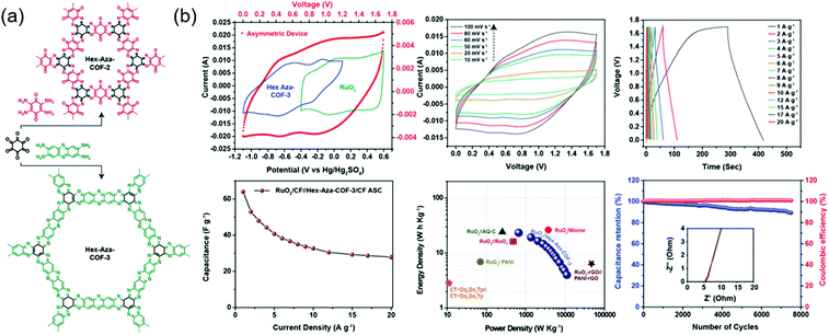
Eddaoudi's group integrated two (benzoquinone and phenazine) redox-active cores to afford COFs that were denoted as Hex-Aza-COF-x (x = 2, 3) (Fig. 6).76 These COFs were synthesized by combining cyclohexanehexone and aromatic tetramines with benzoquinone (Hex-Aza-COF-2) or phenazine (Hex-Aza-COF-3). Both COFs had high capacitances of 585 and 663 F g−1 at 1 A g−1, respectively. Two-electrode cells with Hex-Aza-COF-3 as the negative electrode and RuO2 as the positive electrode delivered a capacitance of 64 F g−1 at 1 A g−1 and a capacity retention of 89% after 7500 cycles at 5 A g−1.
Electric double-layer capacitors
The N moiety does not show an apparent faradaic process in proton-free solutions, which can be applied to non-faradaic EDLC capacitors. Deng's group proposed that the N moiety can promote ion transfer at the electrode interface along with a large surface area associated with EDLC.77 These researchers synthesized tetracyanoquinodimethane-derived covalent triazine-based frameworks, TCNQ-CTFs, and annealed them at 400–900 °C to modulate surface area (1174–4000 m2 g−1), pore size (0.5–4 nm), and nitrogen content (21.79–4.56%). Three-electrode cells with 1.0 M KOH(aq) and all CTF electrodes displayed quasi-rectangular CV curves in the range of −0.8 to 0.1 V and shark-fin galvanostatic curves at 1 A g−1, which was indicative of EDLC behavior. TCNQ-CTF annealed at 800 °C displayed a specific capacitance of 383 F![[thin space (1/6-em)]](https://www.rsc.org/images/entities/char_2009.gif) g−1 at 0.2 A g−1 and a capacitance retention of ∼100% over 10
g−1 at 0.2 A g−1 and a capacitance retention of ∼100% over 10![[thin space (1/6-em)]](https://www.rsc.org/images/entities/char_2009.gif) 000 cycles, which was attributed to the high surface area (3663 m2 g−1) and large nitrogen content (8.13 wt%) of this COF. Charge–discharge curves recorded in a two-electrode system with an ionic liquid electrolyte (1-ethyl-3-methylimidazolium tetrafluoroborate) revealed EDLC behavior. However, a low capacitance of 100 F g−1 at 0.1 A g−1 was observed because of the high viscosity of the ionic liquid. Wang's group improved the electrical conductivity of a triazine-based COF (COFTTA-DHTA) consisting of 4,4′,4′′-(1,3,5-triazine-2,4,6-triyl)trianiline (TTA) with 2,5-dihydroxyterephthaldehyde (DHTA) monomers.78 Notably, a highly ordered COFTTA-DHTA was grown on amine-functionalized CNTs. In a three-electrode system with 1.0 M Na2SO4(aq), a capacitance of 98.7 F g−1 was recorded at 2 A g−1. The total capacitance of 127.5 F g−1 at 0.4 A g−1 was mostly due to EDLC, and the faradaic process arising from phenolic hydroxyl and/or N atoms on COFTTA-DHTA was marginal. Under these conditions, the COFTTA-DHTA/CNT system showed a 30% higher capacitance than the bulk COFTTA-DHTA.
000 cycles, which was attributed to the high surface area (3663 m2 g−1) and large nitrogen content (8.13 wt%) of this COF. Charge–discharge curves recorded in a two-electrode system with an ionic liquid electrolyte (1-ethyl-3-methylimidazolium tetrafluoroborate) revealed EDLC behavior. However, a low capacitance of 100 F g−1 at 0.1 A g−1 was observed because of the high viscosity of the ionic liquid. Wang's group improved the electrical conductivity of a triazine-based COF (COFTTA-DHTA) consisting of 4,4′,4′′-(1,3,5-triazine-2,4,6-triyl)trianiline (TTA) with 2,5-dihydroxyterephthaldehyde (DHTA) monomers.78 Notably, a highly ordered COFTTA-DHTA was grown on amine-functionalized CNTs. In a three-electrode system with 1.0 M Na2SO4(aq), a capacitance of 98.7 F g−1 was recorded at 2 A g−1. The total capacitance of 127.5 F g−1 at 0.4 A g−1 was mostly due to EDLC, and the faradaic process arising from phenolic hydroxyl and/or N atoms on COFTTA-DHTA was marginal. Under these conditions, the COFTTA-DHTA/CNT system showed a 30% higher capacitance than the bulk COFTTA-DHTA.
Zhang's group reported a CNT-conjugated COF (g-C34N6-COF) electrode patterned on a flexible polymer substrate to fabricate micro-supercapacitors.79 These micro-supercapacitors with a LiCl/polyvinyl alcohol electrolyte solution showed an areal capacitance of 15.2 mF![[thin space (1/6-em)]](https://www.rsc.org/images/entities/char_2009.gif) cm−2 at a CV scan rate of 2 mV
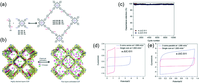
cm−2 at a CV scan rate of 2 mV![[thin space (1/6-em)]](https://www.rsc.org/images/entities/char_2009.gif) s−1. Fang's group reported chemically exfoliated COFs comprising a hydroxyl-containing monomer and a porphyrin-based building block, named JUC (Fig. 7).80 JUC-510 contained a non-metallated porphyrin, whereas JUC-511 and JUC-512 comprised nickel-and copper-coordinated porphyrins, respectively. The exfoliated COFs showed thicknesses of 36, 22, and 19 nm for JUC-510, JUC-511, and JUC-512, respectively. For all COFs, rectangular-shaped CV curves reflecting pure EDLC behavior were observed. Exfoliated JUC-511 and JUC-512 delivered areal capacitances of 5.46 and 5.85 mF cm−2, respectively, at 1000 mV s−1 while featuring a 100% capacitance retention after 1000 galvanostatic cycles. Presumably, the hydroxyl group stabilized these COFs through hydrogen bonding between layers, while the metal ions increased overall conductivity.
s−1. Fang's group reported chemically exfoliated COFs comprising a hydroxyl-containing monomer and a porphyrin-based building block, named JUC (Fig. 7).80 JUC-510 contained a non-metallated porphyrin, whereas JUC-511 and JUC-512 comprised nickel-and copper-coordinated porphyrins, respectively. The exfoliated COFs showed thicknesses of 36, 22, and 19 nm for JUC-510, JUC-511, and JUC-512, respectively. For all COFs, rectangular-shaped CV curves reflecting pure EDLC behavior were observed. Exfoliated JUC-511 and JUC-512 delivered areal capacitances of 5.46 and 5.85 mF cm−2, respectively, at 1000 mV s−1 while featuring a 100% capacitance retention after 1000 galvanostatic cycles. Presumably, the hydroxyl group stabilized these COFs through hydrogen bonding between layers, while the metal ions increased overall conductivity.
Table S2 (ESI†) summarizes all COFs-based capacitors. The above discussion shows that the design of electroactive COFs is of key importance for obtaining higher capacitance. The abundance of COFs prepared to date represents a continuing pursuit of optimum utilization and performance for application in practical capacitors.
Alkali metal–COF hybrid batteries
Commercial lithium-ion batteries (LIBs) use mixed lithium-transition metal (e.g., cobalt and nickel) oxides as positive electrode materials. However, cobalt and nickel are not cheap and have become more expensive with the increasing demand for LIBs caused by the widespread use of portable electronics and electric vehicles. Therefore, alternative electrode materials are highly sought after. For example, the low density and flexibility of organic electrodes make them suitable for portable electronics. The active electrochemical functionalities such as carbonyl, organosulfur, azo, and phenazine moieties are vital for inducing chemical interactions with charge carriers and providing the associated redox potential and capacity.81–83 The challenge of organic electrodes is their susceptibility to side reactions and structural deformation during galvanostatic cycling.84–87 In addition, the poor electronic conductivity of these electrodes (typically from 10−15 to 10−10 S cm−1) impedes the charging rate-determining process of electron transfer.83 Thus, the design of organic molecule-containing frameworks is a task of high significance. Interlocking redox-active moieties establishing covalently linked and π-conjugated structures can improve electronic conductivity and mechanical strength while suppressing the dissolution of molecules. COFs satisfy these requirements and feature periodic nanopores that provide ionic channels to ameliorate ionic conductivity. COFs have been investigated as both negative and positive electrode materials for rechargeable batteries using Li+, Na+, K+, and Zn2+ as charge carriers. During charging, charge carriers are stored in the negative electrode, where the reduction reaction takes place, and settle down in the positive electrode during discharge (Fig. 8). The formation of radicals from the redox-active moieties of COFs undergoing these chemical reactions results in chemical degradation and is an important challenge to be mitigated. At very negative potentials (below 1.0 V vs. Li/Li+ in the LiB case), for example, the charge carrier (Li+) can be intercalated into the COF interlayer, which is similar to that in graphite. Although this process offers additional capacity, the decomposition of non-aqueous electrolytes under these conditions creates a solid–electrolyte interphase layer on the electrode. This layer, despite its positive role in protecting the electrode from the further decomposition of the electrolyte solution, can increase surface resistance and consume the electrolyte solution up to dryness, which results in capacity fading if continuous decomposition occurs. In this section, we highlight the recent development in the design of COF electrodes for non-aqueous Li-, Na-, and K-ion batteries as well as aqueous Zn-ion batteries.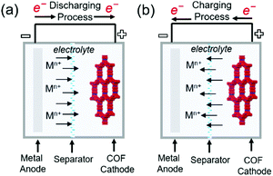 | ||
| Fig. 8 Representation of working principles in alkali metal–COF hybrid batteries. (a) Discharging process (b) charging process in metal–COF batteries. | ||
Lithium-COF batteries
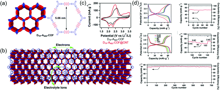
Jiang's group first developed a boronate-linked naphthalene diimide (NDI) COF (DTP–ANDI COF) as an electrode material for Li hybrid cells (Fig. 9).88 Typical two-electrode cells assembled with metallic Li and 1.0 M LiPF6 in 1/1 wt% of ethylene carbonate (EC)/dimethyl carbonate (DMC) showed two lithiation peaks at 2.1 and 2.4 V vs. Li/Li+ due to NDI enolization and a single broad delithiation peak at 2.5 V. The COF-powder-based electrode attained a capacity of 42 mA h g−1 at a current density of 200 mA g−1 (2.4C). However, when DTP–ANDI-COF was directly grown on CNTs, the capacity increased to 67 mA h g−1 (82% of the theoretical value). Electrochemical impedance spectroscopy (EIS) showed that DTP–ANDI COF/CNT featured a lower charge-transfer resistance (8.5 Ω) than DTP–ANDI COF (129 Ω), which underscores the importance of conductive carbon materials for charge transport, as DTP–ANDI COF had a relatively poor electronic conductivity. Notably, DTP–ANDI-COF/CNT showed a stable rate capability at current rates of 2.4–12C and excellent cycling stability, maintaining almost 100% of the original capacity after 700 cycles at 2.4C. The measured capacity approached 90% of the theoretical value. However, as DTP–ANDI-COF/CNT intrinsically contained a small number of redox-active NDI molecules, the capacity was always less than 70 mA h g−1.Subsequently, numerous researchers focused on (1) studying highly conductive carbon nanostructures and their intimate interaction with COFs and (2) increasing the concentration of redox-active functionalities anchored to COFs. Chen's group designed microporous poly(imide-benzoquinone) (PIBN)-based COFs, using quinone and pyromellitic dianhydride moieties to create two redox sites with plentiful of carbonyl groups.89 The COFs were deposited on graphene through in situ polymerization to afford PIBN/G composites. Notably, charge transfer resistance decreased after the integration of PIBN with graphene. Galvanostatic testing of PIBN/G revealed two voltage plateaus and a capacity of 270 mA h g−1 at 0.1C (96.8% of the theoretical value), whereas the capacity of PIBN COF was 86.1% of the theoretical value, which indicated that graphene served as a suitable conducting platform. PIBN/G showed a stable rate capability at a current rate of 10C. After lithiation/delithiation, the disappearance and appearance of imide carbonyl and quinone carbonyl bands was confirmed by in situ Fourier transform infrared spectroscopy. Zhang's group synthesized a COF containing the maximum number of redox-active groups and minimized the concentration of redox-inactive linkages. The resulting BQ1-COF had twelve quinone O atoms and six imine N atoms and was therefore capable of a total of 18 electron transfer processes per repeating molecular unit.90 The observable capacity approached 502.4 mA h g−1 at 0.05C, which corresponded to 65% of the theoretical value. In addition, 81% capacity retention was observed after 1000 cycles at 2C. Zhang's group attempted to increase the total content of the COF (active material) to 70 wt% by mixing it with CNTs (30 wt%) without a binder.91 The researchers integrated a redox-active pyrene-4,5,9,10-tetraone unit with four C![[double bond, length as m-dash]](https://www.rsc.org/images/entities/char_e001.gif) O groups with a planar boroxine (B3O3) to form binder-free PPTODB COFs, which delivered a capacity of 198 mA h g−1 at 20 mA g−1. However, a significant capacity loss of ∼31.7% was observed after 150 cycles at 20 mA g−1 because of the susceptibility of B3O3 linkages to nucleophilic attack.
O groups with a planar boroxine (B3O3) to form binder-free PPTODB COFs, which delivered a capacity of 198 mA h g−1 at 20 mA g−1. However, a significant capacity loss of ∼31.7% was observed after 150 cycles at 20 mA g−1 because of the susceptibility of B3O3 linkages to nucleophilic attack.
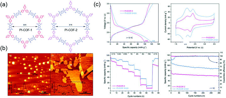
There have also been many alternative studies on COF design aimed at charge transfer enhancement. Wang's group exfoliated a DAAQ-Tp COF using mechanical milling. The exfoliated DAAQ COF, denoted as DAAQ-ECOF, had a thickness of 3–5 nm (10–15 atomic layers) and thus offered the benefit of small Li+ diffusion length.60 Two pairs of redox events were observed at 2.34 and 2.48 V and were ascribed to DAAQ/DAAQ˙− and DAAQ˙−/DAAQ2− conversions, respectively. The DAAQ-ECOF cell utilized 96% of the total DAAQ and achieved a capacity of 145 mA h g−1 (at 20 mA g−1), which was ∼1.3 times higher than that of DAAQ-Tp COF. Moreover, DAAQ-ECOF showed a 98% capacity retention after 1800 cycles at 500 mA g−1, featuring a capacity close to 50% of the theoretical value even at 3000 mA g−1. Huang's group prepared exfoliated pyromellitic imide-based COFs (PI-ECOF-1 and PI-ECOF-2) using tris(4-aminophenyl)amine and 1,3,5-tris(4-aminophenyl)benzene as the monomers (Fig. 10).92 Electrodes were reproducibly prepared from a mixture of ECOF composites with reduced graphene oxide (rGO).89 PI-ECOF-1 cells showed a 79% capacity utilization at 0.1C, while a value of 60% was obtained for PI-COF-1 cells. For a 1/1 mass ratio of COF/rGO, a close-to-theoretical capacity was observed at 0.1C. After 300 cycles at 10 and 1C, capacity retentions of ∼63 and 75% were observed.
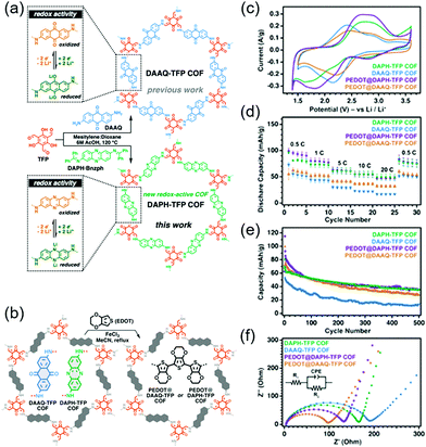
A more groundbreaking way of ameliorating charge transport is the synthesis of highly conductive COFs with enhanced π-conjugation structures. Bu's group compared two COFs: A partially conjugated NDI-based COF with imine linkages (Tb-DANT COF) and a non-conjugated NDI-based COF with β-ketoenamine linkages (Tp-DANT COF).93 The initial capacity of Tb-DANT COF at 1.4C (∼123 mA h g−1) exceeded that of Tp-DANT COF (∼92 mA h g−1). After 300 cycles, Tb-DANT COF cells still maintained 85% of their initial capacity at 3.4C. Dichtel's group demonstrated that suitable redox-active functionalities can increase the energy and power density of bulk COFs (Fig. 11),94 as exemplified by the introduction of a redox-active phenazine group into a β-ketoenamine linkage to produce DAPH-Tp COF. The power density of this COF approached 2268 W kg−1 and was three times greater than that of DAAQ-Tp COF despite their comparable SBET values of ∼1150 m2 g−1. This difference was attributed to the higher Li+ diffusion coefficient of DAPH-Tp (1.1 × 10⁻⁹ cm2 s−1) compared to that of DAAQ-Tp (1.6 × 10⁻¹⁰ cm2 s−1). The presence of conductive PEDOT did not significantly affect the power density and Li+ diffusion coefficient of DAPH-Tp, possibly because this COF exhibited an intrinsically high electrical conductivity. However, both DAPH-Tp and DAAQ-Tp showed a capacity retention of ∼50% after 500 cycles, which indicated the electrochemical instability of their β-ketoenamine linkages.
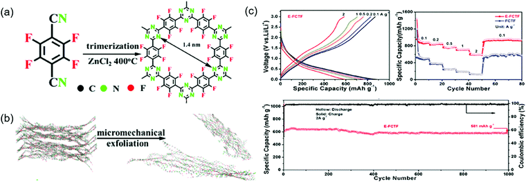
Similarly to commercial graphite, COFs can be used as Li+-intercalating electrode materials at very negative potentials. Wang's group incorporated CNTs into an imine-linked COF with 1,3,5-terformylbenzene and p-diaminobenzene moieties, expecting the π-electron cloud of the benzene ring to trigger 14-electron redox chemistry in the 0.0–3.0 V range.95 The COF itself maintained a capacity of 125 mA h g−1 for 300 cycles at 100 mA g−1, although SBET was low (44.36 m2 g−1) because of the poor COF crystallinity. In contrast, the capacity of the COF/CNT system continuously increased (e.g., from 383 to 1021 mA h g−1 after 325 cycles) during cycling. Using various analyses, the researchers found that the COF interlayer distance increased after lithiation at <1.0 V and suggested that the above capacity increase upon cycling might be caused by the activation of this process. Li+ intercalation into benzene rings accounted for ∼85% of the capacity at the 500th cycle. Density functional theory (DFT) calculations indicated that two Li+ ions reacted with the imine linkage at 1.4–2.7 V, while the remaining 12 Li+ ions were intercalated into COF interlayers. The same group designed an imine-linked TFPB-COF constituting 1,2,4,5-tetrakis-(4-formylphenyl)benzene units and chemically exfoliated this COF to nanosheets (CONs).82 These nanosheets were mixed with MnO2 nanoparticles to prevent the close stacking of the former and promote smooth Li+ intercalation.95 Wang's group also prepared fluorinated triazine-based CONs (named E-FCTF) with a thickness of 4–5 nm (Fig. 12).96 Within a potential range of 0.0–3.0 V, E-FCTF demonstrated 1000 stable cycles, delivering a capacity of 581 mA h g−1 at 2 A g−1. DFT calculations showed that the CON bandgap was reduced to 1.45 eV because of the presence of fluorine substituents, which was held responsible for increased electrical conductivity and improved electrochemical performance. Vaidyanathan's group utilized self-exfoliated triazole CONs, (IISERP)-CON1, with a thickness of 2–6 nm as a Li+-intercalating electrode.97 The SBET of these CONs equaled 507 m2 g−1, while capacity reached 720 mA h g−1 at 100 mA g−1 in the potential range of 0.0–3.0 V. The observation of a weak redox signal of the imine linkage suggested the predominance of Li+ intercalation. After Li+ intercalation, the bandgap was reduced to 0.144 eV. Sun's group employed both azo (N![[double bond, length as m-dash]](https://www.rsc.org/images/entities/char_e001.gif) N) and C
N) and C![[double bond, length as m-dash]](https://www.rsc.org/images/entities/char_e001.gif) O functional groups as redox moieties.98 Azo-based small molecules underwent two-electron transfer in the potential range of 1.2–1.6 V.99 A β-ketoenamine-linked azo COF, Tp-AZO COF, showed a capacity of 306 mA h g−1 at 1 A g−1 for 3000 cycles within 0.0–3.0 V.100 Although many reports determined the total number of transferred electrons from capacity, Li+ intercalation at negative potentials was always accompanied by electrolyte solution decomposition, and future work should therefore address the concomitant formation of solid–electrolyte interphases.
O functional groups as redox moieties.98 Azo-based small molecules underwent two-electron transfer in the potential range of 1.2–1.6 V.99 A β-ketoenamine-linked azo COF, Tp-AZO COF, showed a capacity of 306 mA h g−1 at 1 A g−1 for 3000 cycles within 0.0–3.0 V.100 Although many reports determined the total number of transferred electrons from capacity, Li+ intercalation at negative potentials was always accompanied by electrolyte solution decomposition, and future work should therefore address the concomitant formation of solid–electrolyte interphases.
Zhang's group adopted a new approach to COF electrode fabrication for all-solid-state LIBs. Specifically, a truxenone-based β-ketoenamine-linked COF, named as COF-TRO, was assembled with argyrodite and a 77.5 as solid-state electrolytes and with InLi as the electrode.101 The major lithiation/delithiation events using 6Li+ occurred at 1.55 V at the multiple C![[double bond, length as m-dash]](https://www.rsc.org/images/entities/char_e001.gif) O groups of truxenone, whereas the carbonyl groups of β-ketoenamine linkages were not significantly involved in lithiation/delithiation. The all-solid-state LIB based on the above COF showed a capacity of 268 mA h g−1 at 0.1C, which demonstrated the versatile applicability of COF electrodes to various battery configurations.
O groups of truxenone, whereas the carbonyl groups of β-ketoenamine linkages were not significantly involved in lithiation/delithiation. The all-solid-state LIB based on the above COF showed a capacity of 268 mA h g−1 at 0.1C, which demonstrated the versatile applicability of COF electrodes to various battery configurations.
Aside from the redox moiety, the role of linkage is pivotal. The linkage often governs the electron-transfer rate of the redox core and chemical/structural stability of the COF electrode. Byon's group highlighted this issue by designing three linkages, thiazole-fused ring, imine, and β-ketoenamine, introduced to the azo moiety, and examined these COF electrodes in Li-ion cells.102 The azo integrated with the thiazole-fused ring showed the concerted two-electron transfers within 1.5–2.0 V. The extended π-conjugation structure formed by the thiazole-fused ring stabilized the COF structure during the discharging and charging processes and delivered stable 5000 cycles at 10C. In addition, an excellent rate capability and a power density of 2800 W kg−1 at 40C were evaluated, envisioning that the overlapping p orbitals of azo moieties enhanced electronic conductivity toward out-of-plane of the COF electrode. By contrast, the imine and β-ketoenamine linkages incorporated with azo exhibited a slow two-step electron-transfer process and structural deformation that caused the partial dissolution of COF electrode and impotent cyclability.
Sodium- and potassium-COF batteries
Na- and K-ion batteries have been intensively investigated because of their low cost.103–106 Graphite is the most commonly used negative electrode material for commercial LIBs, where Li+ intercalates into the graphitic layers to form LiC6 (enthalpy of formation, ΔHf = −16.4 mol−1). For Na+ and K+, ΔHf for NaC6/NaC8 and KC8 equals +20 and −27.5 kJ mol−1, respectively.107 The difficulty of Na+ intercalation into graphite highlights the development of alternative carbon materials featuring both amorphous and crystalline structures. In addition, the redox events of sodiation play a more significant role in maintaining a proper capacity level. Considering these characteristics, several COFs have been used as the negative electrodes.Lei and co-workers first demonstrated that organic molecules with an extended π-conjugation can withstand severe volume changes during Na+ insertion, revealing that this effect is further improved in layered structures.108 Pradhan's group reported COF-based sodium-ion batteries (SIBs).109 In the corresponding COF, 1,3,5-tris(4-formylphenyl)benzene and 1,3,5-tris(4-aminophenyl)triazine were interlocked through imine linkages to create C3–C3 symmetry. The CV curve of this TFPB-TAPT COF showed two pairs of redox peaks at 0.9 V and 0.35 V vs. Na/Na+, which corresponded to the redox reactions of imine and triazine N atoms with Na+, respectively. However, the related galvanostatic profiles did not show apparent voltage plateaus, suggesting the predominance of Na+ intercalation and not that of N atom and Na+ reactions. At 30 mA g−1, the capacity approached 246 mA h g−1 for the first cycles and 125 mA h g−1 after 500 cycles, that is, the capacity decay per cycle equaled 0.1%. When current density increased from 30 to 200 mA g−1, specific capacity decreased from 245 to 145 mA h g−1. High-resolution transmission electron microscopy imaging showed that the interlayer distance of TFPB-TAPT COF increased from 3.4 to 3.8 Å through Na+ intercalation (sodiation). Park's group used several layered CONs to mitigate structural distortion during sodiation.110 In this case, monomers were dispersed in an organic solvent and subjected to Stille cross-coupling reactions under solvothermal and reflux conditions. The solvothermal method provided CONs with fibrous morphologies, whereas agglomerated sheets were obtained under reflux conditions. Various types of CONs were prepared by integration of the planar structure of triazine/thiophene or the distorted structure of triphenylamine/thiophene. Among these CONs, the solvothermally synthesized planar triazine/thiophene CON-16 featured the best performance, delivering a capacity of 250 mA h g−1 for 30 cycles at 100 mA g−1, which was ascribed to efficient ion mass transport caused by a large surface area (300 m2 g−1).
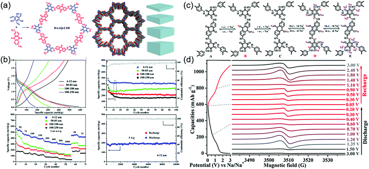
During the cathodic reaction, the redox core is converted to radical intermediates, which may diminish the chemical stability of COFs by favoring chemical decomposition and dimerization. The design of π–π and p–π conjugation systems for delocalizing electrons can mitigate this problem.111,112 Lu and co-workers investigated radical intermediates using a DAAQ-Tp COF electrode (Fig. 13).113 During sodiation, four stepwise processes were observed (as demonstrated by electron paramagnetic resonance spectroscopy, Raman spectroscopy, and computational simulations), namely the formation of the anthraquinone C–O˙ radical, the α-C radical, the β-ketoenamine C–O˙ radical, and the α-C anion. The stability of the α-C radical was critical for determining electrode stability and depended on COF thickness. Four different thicknesses of DAAQ-Tp COF (4–12, 50–85, 100–180, and 100–250 nm) were investigated to reveal that with decreasing stacking thickness, the α-C radical became stabilized, while electron self-exchange between adjacent small-molecule radicals was suppressed. The 4–12 nm-thick DAAQ-Tp COF exhibited a stable capacity of 420 mA h g−1 at 50 mA g−1 and the lowest charge transfer resistance of 146 Ω. During 10![[thin space (1/6-em)]](https://www.rsc.org/images/entities/char_2009.gif) 000 cycles at 5 A g−1, this electrode retained ∼100% of its capacity, showing the best performance among the Na+-intercalating electrodes for SIBs.
000 cycles at 5 A g−1, this electrode retained ∼100% of its capacity, showing the best performance among the Na+-intercalating electrodes for SIBs.
Chen's group increased the number of redox-active sites using nitrogen-rich pyrazine and carbonyl functionalities to accommodate Na+ ions at high concentrations.114 The corresponding honeycomb-morphology TQBQ COF was prepared with a thickness of 5 nm, providing an electronic conductivity of 1.973 × 10⁻⁹ S cm−1. Twelve-Na+ redox chemistry was involved in the potential range of 1.0–3.5 V vs. Na/Na+. As a result, a high specific capacity of 453 mA h g−1 was obtained at 20 mA g−1, and a capacity retention of 96% was obtained after 1000 cycles at 1.0 A g−1. Using a similar strategy, Vaidyanathan's group implanted multiple N heteroatoms into β-ketoenamine-linked COFs to adjust their electronic energy levels.115 These COFs, IISERP-COF16, -17, and -18, contained terphenyl spacers, s-tetrazine units, and s-tetrazine bispyridine units, respectively. The lowest unoccupied molecular orbital (LUMO) energy of IISERP-COF18 was estimated as −4.31 eV, which was lower than that of IISERP-COF16 (−3.75 eV) owing to its high N content. Among them, IISERP-COF-18 showed a stable capacity of 300 mA h g−1 over 1400 cycles at 1 A g−1. This was attributed to the lower charge transfer resistance of IISERP-COF-18 (225 Ω) compared to those of IISERP-COF-16 (620 Ω) and IISERP-COF-17 (600 Ω) due to the enhancement of Na+ transport by the bispyridine-tetrazine segment established along the nanochannel.
Reports on potassium-ion batteries (PIBs) are scarce. Wang's group interlocked 4,4-biphenyldiboronic acid and 2,3,6,7,10,11-hexahydroxytriphenylene to form a boronic ester-linked COF116 with a LUMO energy of −4.23 eV, which was suitable for the negative electrodes of PIBs.117 The related capacity was 203 mA h g−1 at 25 mA g−1 in a potential range of 0.0–3.0 V vs. K/K+, significantly decreasing to 12 mA h g−1 at 5000 mA g−1. The deposition of boronic ester-linked COFs on CNTs increased the capacity to 330 and 68 mA h g−1 at 25 and 5000 mA g−1, respectively, which was ascribed to the increased conductivity and better interaction of K+ through the aromatic π-cloud. This PIB electrode also showed stable behavior during 500 and 4000 cycles at 0.1 and 1 A g−1, respectively.
Aqueous zinc-COF batteries
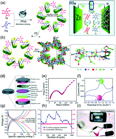
Recently, numerous efforts have been made to construct rechargeable batteries utilizing multivalent metal ions, particularly Zn2+ ions, in aqueous electrolytes. Compared to alkali-ion batteries, which require strict atmospheric conditions, aqueous zinc-ion batteries (ZIBs) offer the benefits of low Zn cost, high capacity (820 mA h g−1 for Zn anode), low redox potential of Zn2+/Zn (−0.76 V vs. SHE), and facile battery fabrication. However, the activation energy for the migration of Zn2+ is greater than that for the migration of monovalent Li+, as these ions have similar sizes (0.74 and 0.76 Å, respectively) but different charges, that is, the increased solvation of Zn2+ ions impedes charge transfer. Consequently, organic electrodes are indispensable for ZIBs, offering the advantages of structural flexibility and ease of coordination with multivalent metal ions. In this case, COFs can play an important role in facilitating Zn2+ migration through porous channels while minimizing coulombic repulsion by efficient molecular design.In their earliest work on zinc-COF batteries, Banerjee's group designed β-ketoenamine-linked and benzoquinone-based HqTp COF electrodes (Fig. 14).118 The electron-rich HqTp backbone comprising C![[double bond, length as m-dash]](https://www.rsc.org/images/entities/char_e001.gif) O and N–H groups could easily coordinate Zn2+ to form HqTp·Zn2+, which enhanced layer stabilization relative to pristine HqTp. Electrostatic potential mapping predicted that the electrochemical reaction of Zn2+ occurred entirely at C
O and N–H groups could easily coordinate Zn2+ to form HqTp·Zn2+, which enhanced layer stabilization relative to pristine HqTp. Electrostatic potential mapping predicted that the electrochemical reaction of Zn2+ occurred entirely at C![[double bond, length as m-dash]](https://www.rsc.org/images/entities/char_e001.gif) O groups, while N–H⋯Zn2+ interactions contributed to chemical stabilization. Aqueous HqTP COF cells showed a capacity of 276 mA h g−1 at 125 mA g−1 in the potential window of 0.2–1.8 V, revealing the participation of 7.5 Zn2+ ions per unit cell. Even at a very high current density of 3750 mA g−1, the cell sustained a capacity of 85.0 mA h g−1 and showed a capacity loss of only 5% after 1000 cycles. Later experiments revealed that not only Zn2+ ions but also H+ ions were involved in the operation of aqueous Zn cells.119 Therefore, ZIBs with COFs are likely to have both battery and capacitor characteristics and are therefore called capatteries. Alshareef's group demonstrated the co-participation of Zn2+ and H+ in reactions with a phenanthroline-based COF (PA-COF) in a zinc-ion capattery.120 The N atoms of PA-COF acted as Zn2+ coordination sites, allowing a maximum of 18 Zn2+ ions per unit structure to participate in discharge. At a current density of 0.1 A g−1 and within a potential range of 0.15–1.75 V, the capacity approached 247 mA h g−1. A capacity loss of 0.38% per cycle was recorded over 10
O groups, while N–H⋯Zn2+ interactions contributed to chemical stabilization. Aqueous HqTP COF cells showed a capacity of 276 mA h g−1 at 125 mA g−1 in the potential window of 0.2–1.8 V, revealing the participation of 7.5 Zn2+ ions per unit cell. Even at a very high current density of 3750 mA g−1, the cell sustained a capacity of 85.0 mA h g−1 and showed a capacity loss of only 5% after 1000 cycles. Later experiments revealed that not only Zn2+ ions but also H+ ions were involved in the operation of aqueous Zn cells.119 Therefore, ZIBs with COFs are likely to have both battery and capacitor characteristics and are therefore called capatteries. Alshareef's group demonstrated the co-participation of Zn2+ and H+ in reactions with a phenanthroline-based COF (PA-COF) in a zinc-ion capattery.120 The N atoms of PA-COF acted as Zn2+ coordination sites, allowing a maximum of 18 Zn2+ ions per unit structure to participate in discharge. At a current density of 0.1 A g−1 and within a potential range of 0.15–1.75 V, the capacity approached 247 mA h g−1. A capacity loss of 0.38% per cycle was recorded over 10![[thin space (1/6-em)]](https://www.rsc.org/images/entities/char_2009.gif) 000 galvanostatic cycles at 1.0 A g−1. When D2O was used, solid-state NMR spectroscopy revealed the presence of D+/OD− and D2O in the PA-COF electrode after discharge, demonstrating the protonation of COF layers. In addition, the precipitation of the triclinic crystals of Zn4(OH)6SO4·5H2O on PA-COF suggested protonation, as this precipitate could be observed at high local pH. The contribution of Zn2+ to the overall capacity was measured as 60% by inductively coupled plasma atomic emission spectroscopy, indicating that the contribution of H+ ions equaled ∼40%.
000 galvanostatic cycles at 1.0 A g−1. When D2O was used, solid-state NMR spectroscopy revealed the presence of D+/OD− and D2O in the PA-COF electrode after discharge, demonstrating the protonation of COF layers. In addition, the precipitation of the triclinic crystals of Zn4(OH)6SO4·5H2O on PA-COF suggested protonation, as this precipitate could be observed at high local pH. The contribution of Zn2+ to the overall capacity was measured as 60% by inductively coupled plasma atomic emission spectroscopy, indicating that the contribution of H+ ions equaled ∼40%.
Table S3 (ESI†) summarizes all COFs in alkali and zinc ion battery. These numerous studies using COFs as alkali-ion battery electrodes have clearly addressed the advantages and challenges of organic-based redox moieties. Although chemical and structural stability could be improved through certain COF designs, future works should still focus on improving both energy and power density for practical use.
COF-Based lithium–sulfur batteries
Lithium–sulfur (Li–S) batteries, which can theoretically deliver a capacity of ∼1675 mA h g−1 and a specific energy density of 2600 W h kg−1, are considered as next-generation Li battery. However, the reduction of elemental sulfur (S8) to polysulfides (PSs; Li2Sn, 2 < n < 8) during discharge (Fig. 15) results in serious active material loss due to dissolution. This problem can be mitigated through the use of porous materials, which can be impregnated with sulfur up to a loading of ∼70 wt%. Various mesoporous carbon electrodes and conducting polymers have been used as positive electrodes for Li–S cells. COFs have also been applied as an electrode platform, and the effects of pore size and molecular moiety on PS species were systematically investigated. In particular, two methods of sulfur confinement have been intensively studied, namely the physisorption/infusion of elemental sulfur into the micro/mesopores of COFs using melt-diffusion methods and the covalent attachment of sulfur (as PS chains) to COF moieties by post-synthetic modifications or as a protective coating on separators. In the former case, the PSs are gradually dissolved during long-term cycling, which results in a notable shuttling effect, namely the transportation of PSs to the negative electrode side. The introduction of sulfiphilic moieties into COFs allows the PSs to preferentially stay around these COFs and suppresses the shuttling effect, which suggests that the two methods can be combined to synergistically enhance the cyclability of Li–S cells.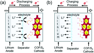 | ||
| Fig. 15 Representation of working principles in COF-based Li–sulfur batteries. (a) Discharging process (b) charging process in COF-based Li–sulfur batteries. | ||
Wang's group began studying COF-based sulfur cells using a covalent triazine framework denoted as CTF-1. Annealing of the mixture of CTF-1 and elemental sulfur at 155 °C allowed the sulfur to infiltrate the COF pores.121 Compared to pristine CTF-1, CTF-1 with sulfur-filled pores (CTF-1/S) featured a lower crystallinity and BET surface area (1.6 m2 g−1vs. 789 m2 g−1). Sulfur was physically adsorbed on the CTF-1 pores and accounted for 34 wt% of the total mass. The COF cells exhibited a typical discharge curve with short (at 2.3 V) and long (at ∼2.1 V) plateaus corresponding to the reduction of sulfur to Li2Sn (2 < n < 8) and the deposition of solid lithium sulfides (Li2S2 and Li2S), respectively. A charge plateau typically appeared at ∼2.3 V. CTF-1/S showed a capacity retention of 63.65% after 50 cycles at 0.1C, which suggested the dissolution of PSs from CTF-1. Zhang's group attempted to confine sulfur in a β-ketoenamine linked Azo COF with a pore size of 2.7 nm and a pore volume density of 0.90 cm3 g−1,122 showing that the sulfur content can be increased to 40 wt% owing to the high pore volume density. Wang's group succeeded in confining sulfur (55 wt%) loaded into a porphyrin-based COF with a pore volume density of 0.71 cm3 g−1 and a pore size of 1.55 nm.123 The low capacity decay of 0.16% per cycle observed for 200 cycles at 0.5C was attributed to the trapping of lithium PSs in small pores.124,125 Practical sulfur batteries require S contents of at least 70 wt%. The same group succeeded in achieving this value using an electron-rich pyrene (Py) unit-based Py-COF,126 which was ascribed to the large pore volume density (1.25 cm3 g−1) and SBET (2093 m2 g−1) of this COF. A capacity decay of 0.048% per cycle was observed over 550 cycles at 5C.
The addition of heteroatoms other than N has been used to suppress PS dissolution and, hence, the shuttle effect. Wang's group studied the impact of fluorine introduction using a sulfur-loaded fluorinated triazine framework, FCTF/S,127 showing that polar semi-ionic C–F bonds attract PSs. The CV profiles of FCTF/S displayed cathodic and anodic waves positively and negatively shifted compared to those of fluorine-free COF/S, respectively, suggesting the occurrence of a fast redox reaction between PSs and F atoms. The initial capacity of 1131 mA h g−1 at 0.5C exceeded that of the fluorine-free COF/S (862 mA h g−1). The FCTF/S COF cells also exhibited a 73.7% capacity retention after 150 cycles at 0.5C, which, however, was similar to that of the fluorine-free COF/S.121 Zhang's group prepared fluorinated crystalline COF-F/S where sulfur was covalently linked through partial nucleophilic substitution.128 Although a sulfur loading of 60 wt% was achieved through covalent bonding and physisorption in COF-F/S pores, a 40 wt% sulfur loss was observed during annealing at 160–225 °C attributed to physisorbed sulfur. The COF-F/S cells showed a capacity decay of 0.04% per cycle at 0.1C. A similar strategy was put forward by Chen's group, who synthesized a vinyl-functionalized COF (COF-V) and subjected it to inverse vulcanization for the covalent linkage of 67 wt% sulfur.129 As a result, capacity decay rates of 0.31% per cycle over 100 cycles at 0.2C and 0.057% per cycle over 1000 cycles at 1C were achieved.
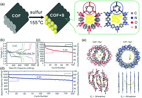
Tang's group considered that positively polarized B and negatively polarized O atoms were responsible for the chemisorption of Sx2− and the trapping of Li+ in lithium PSs, respectively. These researchers synthesized a boronate ester-based COF-1 and impregnated it with sulfur to 40 wt% (Fig. 16).130 The initial capacity of 1655 mA h g−1 was reduced to 929 mA h g−1 after 100 cycles at 0.2C. DFT calculations revealed the presence of highly designed lithiophilic and sulfiphilic sites in COFs for the effective trapping of lithium PSs. Triazine units as lithiophilic sites and boroxine units as sulfiphilic sites were used to prepare TB-COF/S with a 40 wt% sulfur loading.131 The maximum capacity of this COF (1390 mA h g−1) observed after the initial few activations decreased to 945 mA h g−1 after 250 cycles with a coulombic efficiency of 96.5%. When TB-COF/S was dipped into a Li2S6 solution, the solution color changed from orange to brown and then to yellow, which indicated the absorption of Li2S6 on TB-COF/S. The binding energy of boron signals in the related X-ray photoelectron spectra followed the order of TB-COF > TB-COF/S > TB-COF/PSs, which indicated that the ability of the B atom to accept electron density through interactions with S and PSs decreased in the same order. Similar conclusions were drawn for the triazine N atom and Li+ interaction.
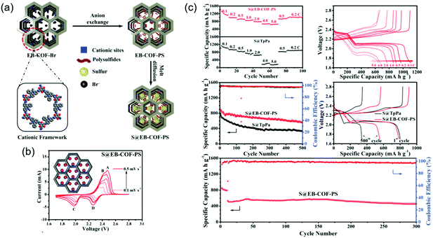
To improve sulfiphilicity, Mak's group prepared a cationic ethidium bromide unit-containing COF (EB-COF-Br) and exchanged Br− ions for S82− (Fig. 17).132 Impregnation of elemental sulfur through physisorption afforded EB-COF-PS/S with a total sulfur content of 71.7 wt%. The initial capacity was measured at 787 mA h g−1 at 0.5C and decreased to 555 mA h g−1 after 500 cycles, which corresponded to a capacity decay of 0.058% per cycle. In the absence of the above anion exchange, EB-COF-Br/S showed an inferior capacity decay of 0.173% per cycle under the same conditions.
Yang's group embedded TiO2 nanodots (∼10 nm in diameter) into a triazine COF to form a TiO2/COF structure with SBET = 809 m2 g−1 and a pore volume density of 0.87 cm3 g−1.133 A shift of the Ti 2p binding energy in TiO2/COF indicated chemical interactions between TiO2 and triazine N atoms. After sulfur loading (70 wt%), TiO2/COF/S cells delivered an initial discharge capacity of 1224 mA h g−1 at 0.2C, which decreased to 1053 mA h g−1 after 300 cycles. The capacity decay of only 0.046% per cycle was the lowest reported for COF-based sulfur batteries thus far. At 0.5C, the capacity decay was measured at 0.030% per cycle, and coulombic efficiency reached ∼100% after 800 cycles following the initial activation cycles, which indicating that PS shuttling was strongly inhibited.
Table S4 (ESI†) summarizes all COFs in Li–sulfur battery. Works on controlling the PS shuttling effect to limit dissolution at desirable levels are still ongoing. Along with electrode development, the design of separators to block the crossover of PSs and the electrolyte solution to mitigate PS dissolution should be further explored to uplift the cyclability of Li–S cells.
Ion conductors
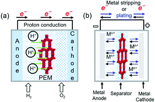
COFs containing ionic or chemical functionalities have been used as proton and ion conductors. Proton-conducting COFs are generally used in the proton-exchange membranes of polymer electrolyte membrane fuel cells (Fig. 18a) and typically contain groups with high proton affinities, e.g., sulfonic acid (–SO3−), azo (N![[double bond, length as m-dash]](https://www.rsc.org/images/entities/char_e001.gif) N), pyrazine, imine (C
N), pyrazine, imine (C![[double bond, length as m-dash]](https://www.rsc.org/images/entities/char_e001.gif) N), and perfluoroalkyl groups and exhibit intrinsic proton conductivity under both hydrous and anhydrous conditions. Alternatively, extrinsic conductivity can be achieved by loading COFs with protons. In most cases, COFs are immersed into acid (e.g., H3PO4) solutions, where protons interact with the triazole, imidazole, or anionic species of COFs. Proton conductivity measured by electrochemical impedance spectroscopy (EIS) indicates a proton-transfer mechanism, while activation energies (Ea) of less than 0.4 eV indicate the Grotthuss hopping mechanism and, hence, fast proton transfer. Higher activation energies reflect vehicular proton transport. Ion-conducting COFs are typically used in battery separators and solid-state electrolytes (Fig. 18b). In the case of Li+ conductors, either lithium salts or single ions are incorporated into COFs in the presence or absence of solvents. Nonetheless, the design of ionically conductive COFs is similar to that of proton-conducting COFs. Table S6 (ESI†) summarizes all COFs used in ion conduction.
N), and perfluoroalkyl groups and exhibit intrinsic proton conductivity under both hydrous and anhydrous conditions. Alternatively, extrinsic conductivity can be achieved by loading COFs with protons. In most cases, COFs are immersed into acid (e.g., H3PO4) solutions, where protons interact with the triazole, imidazole, or anionic species of COFs. Proton conductivity measured by electrochemical impedance spectroscopy (EIS) indicates a proton-transfer mechanism, while activation energies (Ea) of less than 0.4 eV indicate the Grotthuss hopping mechanism and, hence, fast proton transfer. Higher activation energies reflect vehicular proton transport. Ion-conducting COFs are typically used in battery separators and solid-state electrolytes (Fig. 18b). In the case of Li+ conductors, either lithium salts or single ions are incorporated into COFs in the presence or absence of solvents. Nonetheless, the design of ionically conductive COFs is similar to that of proton-conducting COFs. Table S6 (ESI†) summarizes all COFs used in ion conduction.
Proton conductors
The first proton-conducting COF was prepared by Banerjee's group, where they crystallized an azo-interlocked, β-ketoenamine-linked TpAZO COF in the presence of 1.5 M H3PO4(aq) to afford PA@TpAZO (Fig. 19).100 In this COF, H+ ions were anchored at the N atoms of the azo moieties, while the remaining H2PO4− ions were stabilized through hydrogen bonding. For comparison, these researchers also synthesized an azo-free COF and impregnated with H3PO4(aq) to afford PA/TpStb. The solid-state 31P NMR spectrum of PA@TpAZO showed both H3PO4 and H2PO4− signals, whereas that of PA/TpStb displayed only the signal of H3PO4, indicating negligible protonation. The conductivity of PA@TpAZO was measured at 6.7 × 10⁻⁵ S cm−1 at 340 K under the anhydrous conditions typical of a dry argon environment and increased to 9.9 × 10⁻⁴ S cm−1 at a relative humidity (RH) of 98% at 332 K. In comparison, PA/TpStb had a very low conductivity under anhydrous conditions, which increased to 2.3 × 10⁻⁵ S cm−1 at 98% RH. The activation energy (Ea) of PA@TpAZO was as low as at 0.11 eV. Nonetheless, the proton conductivity of PA@TpAZO was lower than that of metal–organic frameworks, Nafion, and sulfonated polyether ether ketone.134–136 The same group used the covalent bonding of proton-conducting functional groups to improve intrinsic proton conductivity.137 Sulfonic acid (–SO3H) groups were integrated with the COF backbone to form TpPa–SO3H. However, as the proton conductivity (1.7 × 10⁻⁵ S cm−1 at 393 K under anhydrous conditions) of this COF was lower than that of PA@TpAZO, the researchers attempted to design a pyridine-based COF backbone and interlocked it with sulfonic acid groups to afford TpPa-(SO3H-Py). Subsequently, TpPa-(SO3H-Py) was immersed in a solution of phytic acid that was less volatile than H3PO4(aq), which significantly increased proton conductivity. Pyridine units intimately interacted with phytic acid, and the proton conductivities of phytic acid-loaded TpPa-Py and TpPa–(SO3H–Py) at 120 °C were determined as 3.0 × 10⁻⁴ and 5 × 10⁻⁴ S cm−1, respectively. Zhao and co-workers prepared a β-ketoenamine-linked COF with two –SO3H groups in the repeat unit (NUS-10), achieving a high conductivity of 3.96 × 10⁻² S cm−1 at room temperature and 97% RH due to the high concentration of sulfonic acid groups.138Jiang's group developed a TPB-DMTP-COF that contained methoxy (–OMe) groups to stabilize the interlayer repulsive force arising from imine linkages.139 This COF showed an SBET of 2072 m2 g−1, which approached the theoretical value of 2098 m2 g−1, and a large pore size of 3.26 nm. TPB-DMTP-COF/triazole, obtained after the loading of triazole units (180 wt%) into TPB-DMTP-COF pores through vapor diffusion, showed a proton conductivity of 1.1 × 10⁻³ S cm−1 at 403 K. The use of imidazole instead of triazole resulted in a proton conductivity of 4.37 × 10⁻³![[thin space (1/6-em)]](https://www.rsc.org/images/entities/char_2009.gif) S
S![[thin space (1/6-em)]](https://www.rsc.org/images/entities/char_2009.gif) cm−1 under similar conditions. A Grotthuss hopping mechanism was proposed to explain this proton conduction based on an activation energy (Ea) of 0.38 eV. Both triazole- and imidazole-containing TPB-DMTP-COFs retained ∼90% of their original weights after storage at 130 °C for one month.
cm−1 under similar conditions. A Grotthuss hopping mechanism was proposed to explain this proton conduction based on an activation energy (Ea) of 0.38 eV. Both triazole- and imidazole-containing TPB-DMTP-COFs retained ∼90% of their original weights after storage at 130 °C for one month.
Zhu's group exchanged the bromide counter-ions of a cationic COF (EB-COF-Br) for PW12O403− (PW12) to afford EB-COF-PW12.140 This anion exchange perturbed crystallinity and the occupancy of pore spaces with the large-size PW12, thus decreasing SBET from 774 to 8 m2 g−1. The proton conductivity of EB-COF-Br was measured at 2.82 × 10⁻⁶ S cm−1 at room temperature and 97% RH, increasing to 3.32 × 10⁻³ S cm−1 for EB-COF-PW12 under similar conditions. The role of anions was probed by several experiments. In particular, low conductivity was observed when phosphotungstic acid was directly mixed with EB-COF-Br. In deuterated solvents, the proton conductivity of EB-COF-Br was reduced by 50%, which suggested that protons originated from dissociated water in a humid environment. The hydrophilic PW12O403− anion could form hydrogen bonds with water molecules. As an alternative approach, N-rich COFs have been employed for proton conduction. For example, aza-COF-1 was synthesized using 2,3,6,7,10,11-hexaaminotriphenylene, and aza-COF-2 was prepared using 1,2,4,5-benzenetetramine, both of which were used as co-precursors, while hexaketocyclohexane was the common precursor.141 The aza units could be protonated in an acidic solution and could also interact with water molecules via hydrogen bonding (O–H⋯N).142,143 The intrinsic proton conductivity under anhydrous conditions was poor (10−8–10−9 S cm−1 at 323 K) but significantly increased (to 10−5–10−6 S cm−1) at 97% RH. The Ea values of aza-COF-1 and aza-COF-2 were measured at 0.78 and 0.96 eV, respectively, suggesting vehicular mechanism–based proton transport. However, after H3PO4 treatment, the proton conductivities of aza-COF-1 and aza-COF-2 at 323 K and 97% RH increased to 1.23 × 10⁻³ and 4.80 × 10⁻³ S cm−1, respectively. The respective Ea values were measured at 0.29 and 0.45 eV, suggesting a mixture of hopping and vehicle transport mechanisms. The higher Ea of aza-COF-2 was ascribed to the smaller crystallite size and numerous grain boundaries, which could increase resistance to proton transport.
Banerjee's group prepared flexible free-standing COF membranes without using pelletization,144 as the high pressure required for this process reduces the crystallinity of COFs and disrupts pore channels to decrease protonic conductivity. Among the three synthesized COFs (TpAZO, TpBD(Me)2, and TpBPy), the first one comprised a proton-conducting azo moiety, while the latter two contained 3,3′-dimethylbiphenyl-4,4′-diamine and 2,2′-bipyridine units, respectively, both of which had no proton-conducting groups. Then, amino-p-toluene sulfonic acid (PTSA·H2O) was impregnated into COF pores to achieve a loading of 8–12 wt%. PTSA-impregnated TpAZO with a thickness of 100–300 μm showed superior proton conductivity, measured to 6.3 × 10⁻² S cm−1 at 303 K and 95% RH and 7.8 × 10⁻² S cm−1 at 353 K and 95% RH. The corresponding Ea (0.23 eV) suggested fast H+ transfer based on the Grotthuss hopping mechanism. In the case of no PTSA·H2O impregnation or simple mixing with PTSA·H2O, the proton conductivity was as low as 10−5–10−6 S cm−1. Despite pelletization, the breaking strain reached 5.4%, a value suitable for flexible membranes. Fuel cells with a proton exchange membrane prepared from PTSA-impregnated TpAZO achieved a maximum power output of 24 mW cm−2 at a current density of 90 mA cm−2. Zhang's group introduced proton-accepting azo and proton-donating phenolic hydroxy groups into a COF with a pore size of 1.8 nm to afford NKCOF-1.145 The proton conductivities of NKCOF-1 and a similar NKCOF with larger pores (2–3.5 nm) were in the range of 10−4–10−3 S cm−1 at 353 K and 98% RH, highlighting the important role of hydroxyl groups. After the impregnation of NKCOF-1 with H3PO4, proton conductivity at 353 K and 98% RH dramatically increased to 1.13 × 10⁻¹ S cm−1, which was comparable to that of Nafion and one order of magnitude greater than that of PTSA-impregnated TpAZO.144,146 The Ea values of NKCOF-1 and H3PO4-impregnated NKCOF-1 (0.24 and 0.14 eV, respectively) indicated that proton transport was dominated by fast H+ hopping. H3PO4-impregnated NKCOF-1 was also used as a proton exchange membrane in fuel cells, in which case a power density of 81 mW cm−2 was achieved at 456 mA cm−2.
The aforementioned studies showed that COF films may exhibit high conductivities under humid conditions, whereas low conductivities are commonly observed under dry conditions. Recently, several reports have focused on enhancing intrinsic proton conductivity regardless of humidity. Horike's group designed superhydrophobic COFs using three perfluoroalkyl-decorated hydrazone-linked 2D COFs, named COF-Fx (x = 6, 8, 10) (Fig. 20).147 Although these COFs exhibited a water contact angle of 144°, that is., were superhydrophobic, their N sites and CF2 chains easily accommodated H3PO4via hydrogen bonding in the porous channels, as evidenced by 2D 1H–31P and 19F–31P NMR spectra. At an H3PO4 content of 62 wt%, COF-F6 had a conductivity of 4.2 × 10⁻² S cm−1 at 313 K under anhydrous conditions, whereas COF-F8 and COF-F10 showed lower conductivities, possibly because of the blocking of porous channels by long perfluoroalkyl chains. The Ea values (0.09–0.54 eV) suggested that proton conduction occurred via the Grotthuss mechanism.
To understand the effect of hydrogen bonding on proton conductivity under anhydrous conditions, Ma's group introduced various (e.g., neutral, polar, Lewis-basic, and positively charged) moieties into the porous channels of COFs.148 The corresponding four COFs, namely the neutral phenylenediamine-based PD-COF, the DAAQ-COF with C![[double bond, length as m-dash]](https://www.rsc.org/images/entities/char_e001.gif) O groups, the 2,4,6-triaminopyrimidine TAP-COF with basic N sites, and the EB-COF with positively charged N atoms were loaded with either H3PO4 through simple mixing or with 1,2,4-triazole by vapor diffusion to generate proton conductivity. Molecular simulations indicated that both H3PO4 and triazole could be aligned to the porous COF channels via hydrogen bonding with polar groups. Furthermore, H3PO4-loaded COFs had lower proton dissociation energies than the corresponding triazole-loaded COFs. In particular, EB-COF had the lowest dissociation energy (2.38 eV), which was ascribed to the formation of an ion pair with H2PO4−. Long-range hydrogen bonding in the H3PO4- or triazole-loaded EB-COF was further confirmed using a dielectric spectrometer. The observed high dielectric constants reflected fast proton dissociation arising from ion pairs in EB-COF. Indeed, the H3PO4-loaded EB-COF showed the highest proton conductivity of 2.77 × 10⁻² S cm−1 at 453 K under anhydrous conditions, and the corresponding Ea (0.35 eV) implied Grotthuss mechanism–based proton transfer. Wang and co-workers improved the concept of hydrogen bonding modulation using imine functional groups on COFs.149 These researchers synthesized imine-linked thiophene-pyrene COFs to further improve electronic conductivity and introduced imidazole into porous channels via vapor diffusion. DFT calculations revealed that the hydrogen-bonding distance between imidazole and imine (N–H⋯N) in thiophene-loaded and thiophene-free COFs was estimated to ∼1.933 and 1.957 Å, respectively. The shorter hydrogen bonding distance in the former case increased the proton hopping rate and the resulting proton conductivity. At 403 K under anhydrous conditions, 50 wt% imidazole-impregnated thiophene and thiophene-free COFs had proton conductivities of ∼3 × 10⁻³ and 8.20 × 10⁻⁴ S cm−1, respectively. Jiang's group employed a similar concept, using 1,3,5-tri(4-aminophenyl)benzene (TPB) and 2,5-dimethylterephthalaldehyde (DMeTP) to form an imine-linked TPB-DMeTP-COF. After the impregnation of its porous channels with neat H3PO4, this COF featured a conductivity of 1.91 S cm−1 at 433 K.150 Neat H3PO4 as the proton carrier formed a long-range hydrogen bonding network with imine N atoms along the porous COF channel to enable a superior proton flow.
O groups, the 2,4,6-triaminopyrimidine TAP-COF with basic N sites, and the EB-COF with positively charged N atoms were loaded with either H3PO4 through simple mixing or with 1,2,4-triazole by vapor diffusion to generate proton conductivity. Molecular simulations indicated that both H3PO4 and triazole could be aligned to the porous COF channels via hydrogen bonding with polar groups. Furthermore, H3PO4-loaded COFs had lower proton dissociation energies than the corresponding triazole-loaded COFs. In particular, EB-COF had the lowest dissociation energy (2.38 eV), which was ascribed to the formation of an ion pair with H2PO4−. Long-range hydrogen bonding in the H3PO4- or triazole-loaded EB-COF was further confirmed using a dielectric spectrometer. The observed high dielectric constants reflected fast proton dissociation arising from ion pairs in EB-COF. Indeed, the H3PO4-loaded EB-COF showed the highest proton conductivity of 2.77 × 10⁻² S cm−1 at 453 K under anhydrous conditions, and the corresponding Ea (0.35 eV) implied Grotthuss mechanism–based proton transfer. Wang and co-workers improved the concept of hydrogen bonding modulation using imine functional groups on COFs.149 These researchers synthesized imine-linked thiophene-pyrene COFs to further improve electronic conductivity and introduced imidazole into porous channels via vapor diffusion. DFT calculations revealed that the hydrogen-bonding distance between imidazole and imine (N–H⋯N) in thiophene-loaded and thiophene-free COFs was estimated to ∼1.933 and 1.957 Å, respectively. The shorter hydrogen bonding distance in the former case increased the proton hopping rate and the resulting proton conductivity. At 403 K under anhydrous conditions, 50 wt% imidazole-impregnated thiophene and thiophene-free COFs had proton conductivities of ∼3 × 10⁻³ and 8.20 × 10⁻⁴ S cm−1, respectively. Jiang's group employed a similar concept, using 1,3,5-tri(4-aminophenyl)benzene (TPB) and 2,5-dimethylterephthalaldehyde (DMeTP) to form an imine-linked TPB-DMeTP-COF. After the impregnation of its porous channels with neat H3PO4, this COF featured a conductivity of 1.91 S cm−1 at 433 K.150 Neat H3PO4 as the proton carrier formed a long-range hydrogen bonding network with imine N atoms along the porous COF channel to enable a superior proton flow.
Ion conductors
The recent surge of interest in solid–electrolyte batteries has inspired numerous studies on ion conductors. In particular, anionic COFs have been extensively used to prepare Li+-conducting channels. Du and co-workers developed a spiro borate–linked COF (ICOF) and mixed it with LiOH as the Li+ carrier during synthesis.151 ICOF had an ionic conductivity of 3.05 × 10⁻⁵ S cm−1 in propylene carbonate at room temperature. The Li+ transference number measured by the Bruce–Vincent–Evans method was 0.80. Feng's group designed a Li+-conducting spiroborate-linked anionic COF functionalized with γ-cyclodextrin (CD-COF-Li).152 The COF was kept in a 1.0 M solution of LiPF6 in 1/1 (v/v) EC/DMC for 12 h, and the process was repeated twice, followed by centrifugation and pelletization to afford 20 wt% LiPF6-loaded CD-COF-Li. The Li+ conductivity was 2.7 × 10⁻³ S cm−1 at 303 K. Li metal cells based on CD-COF-Li were stable during 220 cycles of lithium plating and stripping at 0.085 mA cm−2. The suppression of Li dendrite formation was ascribed to the diminishing anion concentration gradient and suppressed polarization effects. The same group also synthesized an anionic germanate-based COF that showed a Li+ conductivity of 3.5 × 10⁻³ S cm−1 at 373 K after soaking in a solution of 1.0 M LiPF6 in EC/DMC.153Chen's group utilized cationic CONs comprising guanidinium moieties and Cl− counter anions (Fig. 21).154 The chloride ions were replaced with TFSI− upon exposure to an ethanolic solution of LiTFSI to yield Li-CON-TFSI, which featured a Li+ conductivity of 2.09 × 10⁻⁴ S cm−1 at 343 K and an average Li+ transference number of 0.61. This Li+ conductivity was attributed to the separation of Li+ ions from TFSI counter-anions anchored to the cationic framework. As strong ionic bonds often hamper ionic mobility, polyelectrolytes are alternatively employed. Jiang's group designed polyelectrolyte COFs by covalent attachment of 2,5-bis((2-methoxyethoxy)methoxy) or dimethoxy functional groups to afford the imine-linked TPB-BMTP-COF and TPB-DMTP-COF, respectively.155 Subsequent LiClO4 loading onto these COFs through solution diffusion yielded Li+@TPB-DMTP-COF and Li+@TPB-BMTP-COF, which exhibited conductivities of 5.37 × 10⁻⁶ and 1.66 × 10⁻⁴ S cm−1 at 353 K, respectively. Li+@TPB-BMTP-COF (0.87 eV) had a lower Ea than Li+@TPB-DMTP-COF (0.96 eV), as the multiple O atoms of BMTP were arrayed at the polyelectrolyte interface for Li+ transfer. However, the above conductivities were not impressive. Subsequently, the above researchers synthesized triethyleneoxide (TEO)-decorated COFs with TEO ratios of 0–0.5.156 In the case of TPB-DMTP-COF, Li+@[TEO]0.33-TPB-DMTP-COF and Li+@[TEO]0.5-TPB-DMTP-COF showed Li+ conductivities of 2.05 × 10⁻⁴ and 2.49 × 10⁻⁴ S cm−1 at 353 K, respectively, which exceeded those of TEO-free Li+@TPB-DMTP-COF. The conductivity of Li+@[TEO]0.5-TPB-BMTP-COF was smaller than that of the TEO-free COF, probably because of the lower loading of Li+ in the highly condensed structure determined by pore volume shrinkage from 0.96 cm3 g−1 in TPB-BMTP-COF to 0.09 cm3 g−1 in [TEO]0.5-TPB-BMTP-COF before Li+ loading. Horike's group introduced polyethylene oxide functionalities to form COF-PEO-x, where x = 3, 6, or 9 represents the number of PEO units.157 Li+@COF-PEO-9, obtained after impregnation with LiTFSI, showed a high conductivity of 1.33 × 10⁻³ S cm−1 at 473 K. When milled Li+@COF-PEO-9 was applied to Li-ion cells assembled with Li|LiFePO4, galvanostatic cycling within 2.5–4.2 V at 100 °C showed a coulombic efficiency of ∼95% after 10 cycles. Feng's and Wang's groups loaded polyethylene glycol (PEG) onto various types of COFs with neutral, anionic, and cationic moieties through simple soaking in PEG solutions.158 After LiClO4 addition, the cationic PEG-Li+@ethidium bromide unit (EB)-COF-ClO4 showed the highest Li+ conductivity of 1.78 × 10⁻³ S cm−1 at 393 K and a Li+ transference number of 0.60. Similarly, Chen's group synthesized a heteroporous dibenzo[g,p]chrysene-based COF through the introduction of PEG-LiBF4, which resulted in a Li+ conductivity of 2.31 × 10⁻³ S cm−1.159
To increase the Li+ transference number, Lee and co-workers and Lee proposed the use of a solvent-free single Li-ion conductor and fabricated TpPa–SO3Li COF (Fig. 22).160 This sulfonated COF had a Li+ conductivity of 2.7 × 10⁻⁵ S cm−1 and a Li+ transference number of 0.9. The very high transference number was attributed to the small distance required for Li+ hopping between the abundant carbonyl O atoms and sulfonate O atoms, which were aligned in the axial direction of COF nanochannels. The axial migration barrier (7.6 kcal mol−1) was lower than the in-plane migration barrier (31.6 kcal mol−1). Lee, Zhang and co-workers also prepared a single Li-ion conductor COF from lithium imidazolate COFs (Li-ImCOFs).161 Three imidazolate COFs with H, –CH3, and –CF3 substituents were synthesized to impart different electronic conductivities. In the presence of 20 wt% propylene carbonate (PC), the Li+ ionic conductivity/Li+ transference numbers of H–Li–ImCOF, CH3–Li–ImCOF, and CF3–Li–ImCOF were 5.3 × 10⁻³ S cm−1/0.88, 8.0 × 10⁻⁵ S cm−1/0.93, and 7.2 × 10⁻³ S cm−1/0.81, respectively. The high conductivities of H–Li–ImCOF and CF3–Li–ImCOF were ascribed to the high structural order of these COFs and the weak ionic interactions therein.
A COF-based solid-state electrolyte was also applied to multiple charge carriers. Kwak, Lee and co-workers used a TpPa–SO3H COF single-ion conductor for Zn2+ after replacing H+ with Zn2+.162 The resulting TpPa–SO3Zn0.5 COF had a high Zn2+ conductivity of 2.2 × 10⁻⁴ S cm−1 at room temperature, and its hydrated form showed a transference number of 0.91. Furthermore, these researchers used TpPa–SO3Zn0.5 as a solid-state electrolyte in symmetric Zn cells to achieve stable operation for up to 500 h, while the overpotential decreased from 100 to 60 mV. For Zn‖MnO2 cells with the above solid-state electrolyte, a capacity retention of 73% was observed after 800 cycles at 0.6 A g−1.
Summary and outlook
We highlighted the advances in the development of COFs for use as the electrodes of organic capacitors and batteries or as ionic conductors for membranes. The rich diversity of synthetic methods and the feasibility of chemical designs make COFs attractive for customized organic materials. In addition, structural characteristics such as pore diameter, pore volume, surface area, interlayer interactions, and thickness determine the stability, chemical reactivity, and ionic/electronic conductivity of COFs. In the COF structure, the role of chemical functional groups can be addressed with respect to rigidity and electrochemical activity. Studies of design-dependent cell performance and mechanistic elucidation have accumulated the knowledge, which allows us to develop better organic materials and improve storage performance.Despite the significant progress in this field, future works should still focus on improving conductivity, increasing the concentrated integration of active moieties, enhancing chemical stability, and lowering synthetic cost and time to make COFs practically useful. At this point, we would like to note some important but less spotlighted issues. Typically, ion transport in bulk and crystalline COFs preferentially occurs in the axial direction through porous channels.160 However, electron transport in the stacking direction remains unexplored, although this factor determines the electronic conductivity of bulk COF electrodes. The presence of pπ–pπ orbital coupling to the axial direction may further amplify this electron transport, which suggests the need for COFs with interlayered designs.102,163 The fabrication of thin films using exfoliation and direct thin-film growth has been extensively investigated to solve the problem of low electronic conductivity. However, thin films contain only a small amount of active material, which is not acceptable for industrial production. Therefore, a more practical direction of the research approach should be needed.
We should also point out that reconstructed COFs typically comprise a redox core moiety and linkages. Although linkages are essentially responsible for the chemical and mechanical rigidity of the electrode structure, they can eventually reduce the specific capacity and gravimetric energy density. Therefore, it is encouraged that linkages not only determine structural rigidity but also act as redox-active sites.
Overall, the redox molecule quantity, concentrated integration, and conductivity of COFs should be balanced for practical electrode materials. All research directions are based on a fundamental understanding of electrochemical and chemical processes. A systematic comparison of a series of COF structures, chemical motifs, and computational calculations is expected to deepen our knowledge of the related redox mechanisms and interfacial reactions. The reduction of synthetic costs and the number/complexity of synthetic processes are the following step required for mass production. We believe that the development of a new class of future electrodes offers numerous opportunities and will change our lives and technologies.
Conflicts of interest
The authors declare no conflict of interest.Acknowledgements
This work was supported by the Samsung Research Funding & Incubation Center of Samsung Electronics under Project Number SRFC-MA1702-05.References
- Z. Yang, J. Zhang, M. C. Kintner-Meyer, X. Lu, D. Choi, J. P. Lemmon and J. Liu, Chem. Rev., 2011, 111, 3577–3613 CrossRef CAS PubMed.
- D. R. Rolison and L. F. Nazar, MRS Bull., 2011, 36, 486–493 CrossRef CAS.
- A. Manthiram, Y. Fu and Y.-S. Su, Acc. Chem. Res., 2013, 46, 1125–1134 CrossRef CAS PubMed.
- X.-P. Gao and H.-X. Yang, Energy Environ. Sci., 2010, 3, 174–189 RSC.
- T. Kim, W. Song, D.-Y. Son, L. K. Ono and Y. Qi, J. Mater. Chem. A, 2019, 7, 2942–2964 RSC.
- D. Chen, Z. Lou, K. Jiang and G. Shen, Adv. Funct. Mater., 2018, 28, 1805596 CrossRef.
- A. M. Zamarayeva, A. E. Ostfeld, M. Wang, J. K. Duey, I. Deckman, B. P. Lechêne, G. Davies, D. A. Steingart and A. C. Arias, Sci. Adv., 2017, 3, e1602051 CrossRef PubMed.
- J. B. Goodenough, Energy Environ. Sci., 2014, 7, 14–18 RSC.
- V. Augustyn, P. Simon and B. Dunn, Energy Environ. Sci., 2014, 7, 1597–1614 RSC.
- M. Shao, Q. Chang, J.-P. Dodelet and R. Chenitz, Chem. Rev., 2016, 116, 3594–3657 CrossRef CAS PubMed.
- N.-T. Suen, S.-F. Hung, Q. Quan, N. Zhang, Y.-J. Xu and H. M. Chen, Chem. Soc. Rev., 2017, 46, 337–365 RSC.
- A. Eftekhari, Int. J. Hydrogen Energy, 2017, 42, 11053–11077 CrossRef CAS.
- S. Fang, D. Bresser and S. Passerini, Adv. Energy Mater., 2020, 10, 1902485 CrossRef CAS.
- D. Larcher and J.-M. Tarascon, Nat. Chem., 2015, 7, 19–29 CrossRef CAS PubMed.
- P. Poizot, J. Gaubicher, S. Renault, L. Dubois, Y. Liang and Y. Yao, Chem. Rev., 2020, 120, 6490–6557 CrossRef CAS.
- D. Xu, M. Liang, S. Qi, W. Sun, L.-P. Lv, F.-H. Du, B. Wang, S. Chen, Y. Wang and Y. Yu, ACS Nano, 2021, 15, 47–80 CrossRef CAS.
- T. B. Schon, B. T. McAllister, P.-F. Li and D. S. Seferos, Chem. Soc. Rev., 2016, 45, 6345–6404 RSC.
- Z. Zhao-Karger, P. Gao, T. Ebert, S. Klyatskaya, Z. Chen, M. Ruben and M. Fichtner, Adv. Mater., 2019, 31, 1806599 CrossRef PubMed.
- S. Lee, G. Kwon, K. Ku, K. Yoon, S. K. Jung, H. D. Lim and K. Kang, Adv. Mater., 2018, 30, 1704682 CrossRef PubMed.
- A. Saal, T. Hagemann and U. S. Schubert, Adv. Energy Mater., 2020, 2001984 CrossRef.
- J. Lopez, D. G. Mackanic, Y. Cui and Z. Bao, Nat. Rev. Mater., 2019, 4, 312–330 CrossRef CAS.
- J. F. Mike and J. L. Lutkenhaus, ACS Macro Lett., 2013, 2, 839–844 CrossRef CAS.
- A. P. Cote, A. I. Benin, N. W. Ockwig, M. O'Keeffe, A. J. Matzger and O. M. Yaghi, Science, 2005, 310, 1166–1170 CrossRef CAS PubMed.
- H. M. El-Kaderi, J. R. Hunt, J. L. Mendoza-Cortés, A. P. Côté, R. E. Taylor, M. O'Keeffe and O. M. Yaghi, Science, 2007, 316, 268–272 CrossRef CAS PubMed.
- X. Feng, X. Ding and D. Jiang, Chem. Soc. Rev., 2012, 41, 6010–6022 RSC.
- S.-Y. Ding and W. Wang, Chem. Soc. Rev., 2013, 42, 548–568 RSC.
- N. Huang, P. Wang and D. Jiang, Nat. Rev. Mater., 2016, 1, 1–19 Search PubMed.
- S. Kandambeth, K. Dey and R. Banerjee, J. Am. Chem. Soc., 2019, 141, 1807–1822 CrossRef CAS PubMed.
- M. S. Lohse and T. Bein, Adv. Funct. Mater., 2018, 28, 1705553 CrossRef.
- H. Wang, Z. Zeng, P. Xu, L. Li, G. Zeng, R. Xiao, Z. Tang, D. Huang, L. Tang, C. Lai, D. Jiang, Y. Liu, H. Yi, L. Qin, S. Ye, X. Ren and W. Tang, Chem. Soc. Rev., 2019, 48, 488–516 RSC.
- J. L. Segura, M. J. Mancheño and F. Zamora, Chem. Soc. Rev., 2016, 45, 5635–5671 RSC.
- D. Rodríguez-San-Miguel and F. Zamora, Chem. Soc. Rev., 2019, 48, 4375–4386 RSC.
- X. Guan, F. Chen, Q. Fang and S. Qiu, Chem. Soc. Rev., 2020, 49, 1357–1384 RSC.
- X. Li and K. P. Loh, ACS Mater. Lett., 2019, 1, 327–335 CrossRef CAS.
- J.-M. Seo, H.-J. Noh, H. Y. Jeong and J.-B. Baek, J. Am. Chem. Soc., 2019, 141, 11786–11790 CrossRef CAS PubMed.
- E. Jin, Z. Lan, Q. Jiang, K. Geng, G. Li, X. Wang and D. Jiang, Chem, 2019, 5, 1632–1647 CAS.
- A. Halder, M. Ghosh, M. A. Khayum, S. Bera, M. Addicoat, H. S. Sasmal, S. Karak, S. Kurungot and R. Banerjee, J. Am. Chem. Soc., 2018, 140, 10941–10945 CrossRef CAS PubMed.
- B. P. Biswal, S. Chandra, S. Kandambeth, B. Lukose, T. Heine and R. Banerjee, J. Am. Chem. Soc., 2013, 135, 5328–5331 CrossRef CAS PubMed.
- V. Singh, S. Jang, N. K. Vishwakarma and D.-P. Kim, NPG Asia Mater., 2018, 10, e456 CrossRef.
- X. Guan, Y. Ma, H. Li, Y. Yusran, M. Xue, Q. Fang, Y. Yan, V. Valtchev and S. Qiu, J. Am. Chem. Soc., 2018, 140, 4494–4498 CrossRef CAS PubMed.
- B. Diaz de Greñu, J. Torres, J. García-González, S. Muñoz-Pina, R. de los Reyes, A. M. Costero, P. Amorós and J. Ros-Lis, ChemSusChem, 2021, 14, 208–233 CrossRef PubMed.
- Y. Peng, W. K. Wong, Z. Hu, Y. Cheng, D. Yuan, S. A. Khan and D. Zhao, Chem. Mater., 2016, 28, 5095–5101 CrossRef CAS.
- S. Karak, S. Kandambeth, B. P. Biswal, H. S. Sasmal, S. Kumar, P. Pachfule and R. Banerjee, J. Am. Chem. Soc., 2017, 139, 1856–1862 CrossRef CAS.
- S. Kandambeth, A. Mallick, B. Lukose, M. V. Mane, T. Heine and R. Banerjee, J. Am. Chem. Soc., 2012, 134, 19524–19527 CrossRef CAS.
- S. K. Yang, A. V. Ambade and M. Weck, J. Am. Chem. Soc., 2010, 132, 1637–1645 CrossRef CAS PubMed.
- S. Cai, B. Sun, X. Li, Y. Yan, A. Navarro, A. Garzón-Ruiz, H. Mao, R. Chatterjee, J. Yano, C. Zhu, J. A. Reimer, S. Zheng, J. Fan, W. Zhang and Y. Liu, ACS Appl. Mater. Interfaces, 2020, 12, 19054–19061 CrossRef CAS PubMed.
- F. Auras, L. Ascherl, A. H. Hakimioun, J. T. Margraf, F. C. Hanusch, S. Reuter, D. Bessinger, M. sDöblinger, C. Hettstedt and K. Karaghiosoff, J. Am. Chem. Soc., 2016, 138, 16703–16710 CrossRef CAS.
- L. Ascherl, T. Sick, J. T. Margraf, S. H. Lapidus, M. Calik, C. Hettstedt, K. Karaghiosoff, M. Döblinger, T. Clark and K. W. Chapman, Nat. Chem., 2016, 8, 310–316 CrossRef CAS.
- C. R. DeBlase, K. Hernández-Burgos, K. E. Silberstein, G. G. Rodríguez-Calero, R. P. Bisbey, H. D. Abruña and W. R. Dichtel, ACS Nano, 2015, 9, 3178–3183 CrossRef CAS PubMed.
- A. M. Evans, L. R. Parent, N. C. Flanders, R. P. Bisbey, E. Vitaku, M. S. Kirschner, R. D. Schaller, L. X. Chen, N. C. Gianneschi and W. R. Dichtel, Science, 2018, 361, 52–57 CrossRef CAS PubMed.
- S. Haldar, K. Roy, S. Nandi, D. Chakraborty, D. Puthusseri, Y. Gawli, S. Ogale and R. Vaidhyanathan, Adv. Energy Mater., 2018, 8, 1702170 CrossRef.
- S. Haldar, K. Roy, R. Kushwaha, S. Ogale and R. Vaidhyanathan, Adv. Energy Mater., 2019, 9, 1902428 CrossRef CAS.
- C. Liu, Y. Yu, W. Zhang, Q. Zeng and S. Lei, Chem. – Eur. J., 2016, 22, 18412–18418 CrossRef CAS PubMed.
- G. Zhan, Z.-F. Cai, M. Martínez-Abadía, A. Mateo-Alonso and S. De Feyter, J. Am. Chem. Soc., 2020, 142, 5964–5968 CrossRef CAS PubMed.
- Z.-F. Cai, G. Zhan, L. Daukiya, S. Eyley, W. Thielemans, K. Severin and S. De Feyter, J. Am. Chem. Soc., 2019, 141, 11404–11408 CrossRef CAS PubMed.
- D. Rodríguez-San-Miguel, C. Montoro and F. Zamora, Chem. Soc. Rev., 2020, 49, 2291–2302 RSC.
- Z. Kang, Y. Peng, Y. Qian, D. Yuan, M. A. Addicoat, T. Heine, Z. Hu, L. Tee, Z. Guo and D. Zhao, Chem. Mater., 2016, 28, 1277–1285 CrossRef CAS.
- M. A. Khayum, S. Kandambeth, S. Mitra, S. B. Nair, A. Das, S. S. Nagane, R. Mukherjee and R. Banerjee, Angew. Chem., 2016, 128, 15833–15837 CrossRef.
- S. Mitra, S. Kandambeth, B. P. Biswal, M. A. Khayum, C. K. Choudhury, M. Mehta, G. Kaur, S. Banerjee, A. Prabhune, S. Verma, S. Roy, U. K. Kharul and R. Banerjee, J. Am. Chem. Soc., 2016, 138, 2823–2828 CrossRef CAS.
- S. Wang, Q. Wang, P. Shao, Y. Han, X. Gao, L. Ma, S. Yuan, X. Ma, J. Zhou, X. Feng and B. Wang, J. Am. Chem. Soc., 2017, 139, 4258–4261 CrossRef CAS.
- X.-H. Liu, C.-Z. Guan, S.-Y. Ding, W. Wang, H.-J. Yan, D. Wang and L.-J. Wan, J. Am. Chem. Soc., 2013, 135, 10470–10474 CrossRef CAS PubMed.
- P. Sharma and T. Bhatti, Energy Convers. Manage., 2010, 51, 2901–2912 CrossRef CAS.
- J. Ding, W. Hu, E. Paek and D. Mitlin, Chem. Rev., 2018, 118, 6457–6498 CrossRef CAS PubMed.
- C. R. DeBlase, K. E. Silberstein, T.-T. Truong, H. D. Abruña and W. R. Dichtel, J. Am. Chem. Soc., 2013, 135, 16821–16824 CrossRef CAS PubMed.
- Z. Zha, L. Xu, Z. Wang, X. Li, Q. Pan, P. Hu and S. Lei, ACS Appl. Mater. Interfaces, 2015, 7, 17837–17843 CrossRef CAS PubMed.
- Q. Xu, S. Dalapati and D. Jiang, ACS Cent. Sci., 2016, 2, 586–587 CrossRef CAS PubMed.
- C. R. Mulzer, L. Shen, R. P. Bisbey, J. R. McKone, N. Zhang, H. D. Abruña and W. R. Dichtel, ACS Cent. Sci., 2016, 2, 667–673 CrossRef CAS.
- M. A. Khayum, V. Vijayakumar, S. Karak, S. Kandambeth, M. Bhadra, K. Suresh, N. Acharambath, S. Kurungot and R. Banerjee, ACS Appl. Mater. Interfaces, 2018, 10, 28139–28146 CrossRef PubMed.
- F. Xu, H. Xu, X. Chen, D. Wu, Y. Wu, H. Liu, C. Gu, R. Fu and D. Jiang, Angew. Chem., 2015, 127, 6918–6922 CrossRef.
- A. M. Khattak, Z. A. Ghazi, B. Liang, N. A. Khan, A. Iqbal, L. Li and Z. Tang, J. Mater. Chem. A, 2016, 4, 16312–16317 RSC.
- P. Bhanja, K. Bhunia, S. K. Das, D. Pradhan, R. Kimura, Y. Hijikata, S. Irle and A. Bhaumik, ChemSusChem, 2017, 10, 921–929 CrossRef CAS PubMed.
- S. Chandra, D. Roy Chowdhury, M. Addicoat, T. Heine, A. Paul and R. Banerjee, Chem. Mater., 2017, 29, 2074–2080 CrossRef CAS.
- S. Haldar, R. Kushwaha, R. Maity and R. Vaidhyanathan, ACS Mater. Lett., 2019, 1, 490–497 CrossRef CAS.
- L. Li, F. Lu, R. Xue, B. Ma, Q. Li, N. Wu, H. Liu, W. Yao, H. Guo and W. Yang, ACS Appl. Mater. Interfaces, 2019, 11, 26355–26363 CrossRef CAS PubMed.
- A. Halder, S. Karak, M. Addicoat, S. Bera, A. Chakraborty, S. H. Kunjattu, P. Pachfule, T. Heine and R. Banerjee, Angew. Chem., Int. Ed., 2018, 57, 5797–5802 CrossRef CAS PubMed.
- S. Kandambeth, J. Jia, H. Wu, V. S. Kale, P. T. Parvatkar, J. Czaban-Jóźwiak, S. Zhou, X. Xu, Z. O. Ameur, E. Abou-Hamad, A.-H. Emwas, O. Shekhah, H. N. Alshareef and M. Eddaoudi, Adv. Energy Mater., 2020, 10, 2001673 CrossRef CAS.
- Y. Li, S. Zheng, X. Liu, P. Li, L. Sun, R. Yang, S. Wang, Z. S. Wu, X. Bao and W. Q. Deng, Angew. Chem., 2018, 130, 8124–8128 CrossRef.
- B. Sun, J. Liu, A. Cao, W. Song and D. Wang, Chem. Commun., 2017, 53, 6303–6306 RSC.
- J. Xu, Y. He, S. Bi, M. Wang, P. Yang, D. Wu, J. Wang and F. Zhang, Angew. Chem., 2019, 131, 12193–12197 CrossRef.
- Y. Yusran, H. Li, X. Guan, D. Li, L. Tang, M. Xue, Z. Zhuang, Y. Yan, V. Valtchev, S. Qiu and Q. Fang, Adv. Mater., 2020, 32, 1907289 CrossRef CAS PubMed.
- T. Suga, H. Ohshiro, S. Sugita, K. Oyaizu and H. Nishide, Adv. Mater., 2009, 21, 1627–1630 CrossRef CAS.
- Y. Lu, X. Hou, L. Miao, L. Li, R. Shi, L. Liu and J. Chen, Angew. Chem., Int. Ed., 2019, 58, 7020–7024 CrossRef CAS.
- Y. Lu and J. Chen, Nat. Rev. Chem., 2020, 4, 127–142 CrossRef CAS.
- K. Zhang, C. Guo, Q. Zhao, Z. Niu and J. Chen, Adv. Sci., 2015, 2, 1500018 CrossRef.
- W. Huang, Z. Zhu, L. Wang, S. Wang, H. Li, Z. Tao, J. Shi, L. Guan and J. Chen, Angew. Chem., Int. Ed., 2013, 52, 9162–9166 CrossRef CAS PubMed.
- Z. Zhu, M. Hong, D. Guo, J. Shi, Z. Tao and J. Chen, J. Am. Chem. Soc., 2014, 136, 16461–16464 CrossRef CAS.
- M. Wu, Y. Cui, A. Bhargav, Y. Losovyj, A. Siegel, M. Agarwal, Y. Ma and Y. Fu, Angew. Chem., 2016, 128, 10181–10185 CrossRef.
- F. Xu, S. Jin, H. Zhong, D. Wu, X. Yang, X. Chen, H. Wei, R. Fu and D. Jiang, Sci. Rep., 2015, 5, 8225 CrossRef CAS PubMed.
- Z. Luo, L. Liu, J. Ning, K. Lei, Y. Lu, F. Li and J. Chen, Angew. Chem., Int. Ed., 2018, 57, 9443–9446 CrossRef CAS PubMed.
- M. Wu, Y. Zhao, B. Sun, Z. Sun, C. Li, Y. Han, L. Xu, Z. Ge, Y. Ren and M. Zhang, Nano Energy, 2020, 70, 104498 CrossRef CAS.
- C. J. Yao, Z. Wu, J. Xie, F. Yu, W. Guo, Z. J. Xu, D. S. Li, S. Zhang and Q. Zhang, ChemSusChem, 2020, 13, 2457–2563 CrossRef CAS.
- Z. Wang, Y. Li, P. Liu, Q. Qi, F. Zhang, G. Lu, X. Zhao and X. Huang, Nanoscale, 2019, 11, 5330–5335 RSC.
- D.-H. Yang, Z.-Q. Yao, D. Wu, Y.-H. Zhang, Z. Zhou and X.-H. Bu, J. Mater. Chem. A, 2016, 4, 18621–18627 RSC.
- E. Vitaku, C. N. Gannett, K. L. Carpenter, L. Shen, H. D. Abruña and W. R. Dichtel, J. Am. Chem. Soc., 2020, 142, 16–20 CrossRef CAS PubMed.
- Z. Lei, Q. Yang, Y. Xu, S. Guo, W. Sun, H. Liu, L.-P. Lv, Y. Zhang and Y. Wang, Nat. Commun., 2018, 9, 1–13 CrossRef PubMed.
- H. Zhang, W. Sun, X. Chen and Y. Wang, ACS Nano, 2019, 13, 14252–14261 CrossRef CAS PubMed.
- S. Haldar, K. Roy, S. Nandi, D. Chakraborty, D. Puthusseri, Y. Gawli, S. Ogale and R. Vaidhyanathan, Adv. Energy Mater., 2018, 8, 1702170 CrossRef.
- G. Zhao, Y. Zhang, Z. Gao, H. Li, S. Liu, S. Cai, X. Yang, H. Guo and X. Sun, ACS Energy Lett., 2020, 5, 1022–1031 CrossRef CAS.
- C. Luo, O. Borodin, X. Ji, S. Hou, K. J. Gaskell, X. Fan, J. Chen, T. Deng, R. Wang, J. Jiang and C. Wang, Proc. Natl. Acad. Sci. U. S. A., 2018, 115, 2004–2009 CrossRef CAS PubMed.
- S. Chandra, T. Kundu, S. Kandambeth, R. BabaRao, Y. Marathe, S. M. Kunjir and R. Banerjee, J. Am. Chem. Soc., 2014, 136, 6570–6573 CrossRef CAS PubMed.
- X. Yang, Y. Hu, N. Dunlap, X. Wang, S. Huang, Z. Su, S. Sharma, Y. Jin, F. Huang, X. Wang, S.-H. Lee and W. Zhang, Angew. Chem., Int. Ed., 2020, 59, 20385–20389 CrossRef CAS PubMed.
- V. Singh, J. Kim, B. Kang, J. Moon, S. Kim, W. Y. Kim and H. R. Byon, Adv. Energy Mater., 2021 DOI:10.1002/aenm.202003735.
- N. Yabuuchi, K. Kubota, M. Dahbi and S. Komaba, Chem. Rev., 2014, 114, 11636–11682 CrossRef CAS PubMed.
- W. Zhang, F. Zhang, F. Ming and H. N. Alshareef, EnergyChem, 2019, 1, 100012 CrossRef.
- J. C. Pramudita, D. Sehrawat, D. Goonetilleke and N. Sharma, Adv. Energy Mater., 2017, 7, 1602911 CrossRef.
- Y.-S. Xu, S.-Y. Duan, Y.-G. Sun, D.-S. Bin, X.-S. Tao, D. Zhang, Y. Liu, A.-M. Cao and L.-J. Wan, J. Mater. Chem. A, 2019, 7, 4334–4352 RSC.
- Z. Wang, S. M. Selbach and T. Grande, RSC Adv., 2014, 4, 4069–4079 CAS.
- C. Wang, Y. Xu, Y. Fang, M. Zhou, L. Liang, S. Singh, H. Zhao, A. Schober and Y. Lei, J. Am. Chem. Soc., 2015, 137, 3124–3130 CrossRef CAS PubMed.
- B. C. Patra, S. K. Das, A. Ghosh, K. A. Raj, P. Moitra, M. Addicoat, S. Mitra, A. Bhaumik, S. Bhattacharya and A. Pradhan, J. Mater. Chem. A, 2018, 6, 16655–16663 RSC.
- M.-S. Kim, W.-J. Lee, S.-M. Paek and J. K. Park, ACS Appl. Mater. Interfaces, 2018, 10, 32102–32111 CrossRef CAS PubMed.
- M. Kolek, F. Otteny, P. Schmidt, C. Mück-Lichtenfeld, C. Einholz, J. Becking, E. Schleicher, M. Winter, P. Bieker and B. Esser, Energy Environ. Sci., 2017, 10, 2334–2341 RSC.
- S. Wu, W. Wang, M. Li, L. Cao, F. Lyu, M. Yang, Z. Wang, Y. Shi, B. Nan and S. Yu, Nat. Commun., 2016, 7, 1–11 Search PubMed.
- S. Gu, S. Wu, L. Cao, M. Li, N. Qin, J. Zhu, Z. Wang, Y. Li, Z. Li, J. Chen and Z. Lu, J. Am. Chem. Soc., 2019, 141, 9623–9628 CrossRef CAS PubMed.
- R. Shi, L. Liu, Y. Lu, C. Wang, Y. Li, L. Li, Z. Yan and J. Chen, Nat. Commun., 2020, 11, 178 CrossRef CAS.
- S. Haldar, D. Kaleeswaran, D. Rase, K. Roy, S. Ogale and R. Vaidhyanathan, Nanoscale Horiz., 2020, 5, 1264–1273 RSC.
- X. Chen, H. Zhang, C. Ci, W. Sun and Y. Wang, ACS Nano, 2019, 13, 3600–3607 CrossRef CAS PubMed.
- Q. Xue, D. Li, Y. Huang, X. Zhang, Y. Ye, E. Fan, L. Li, F. Wu and R. Chen, J. Mater. Chem. A, 2018, 6, 12559–12564 RSC.
- M. A. Khayum, M. Ghosh, V. Vijayakumar, A. Halder, M. Nurhuda, S. Kumar, M. Addicoat, S. Kurungot and R. Banerjee, Chem. Sci., 2019, 10, 8889–8894 RSC.
- M. Na, Y. Oh and H. R. Byon, Chem. Mater., 2020, 32, 6990–6997 CrossRef CAS.
- W. Wang, V. S. Kale, Z. Cao, S. Kandambeth, W. Zhang, J. Ming, P. T. Parvatkar, E. Abou-Hamad, O. Shekhah, L. Cavallo, M. Eddaoudi and H. N. Alshareef, ACS Energy Lett., 2020, 5, 2256–2264 CrossRef CAS.
- H. Liao, H. Ding, B. Li, X. Ai and C. Wang, J. Mater. Chem. A, 2014, 2, 8854–8858 RSC.
- X. Yang, B. Dong, H. Zhang, R. Ge, Y. Gao and H. Zhang, RSC Adv., 2015, 5, 86137–86143 RSC.
- H. Liao, H. Wang, H. Ding, X. Meng, H. Xu, B. Wang, X. Ai and C. Wang, J. Mater. Chem. A, 2016, 4, 7416–7421 RSC.
- A. Schneider, C. Weidmann, C. Suchomski, H. Sommer, J. r. Janek and T. Brezesinski, Chem. Mater., 2015, 27, 1674–1683 CrossRef CAS.
- Q. Pang and L. F. Nazar, ACS Nano, 2016, 10, 4111–4118 CrossRef CAS PubMed.
- Y. Meng, G. Lin, H. Ding, H. Liao and C. Wang, J. Mater. Chem. A, 2018, 6, 17186–17191 RSC.
- F. Xu, S. Yang, G. Jiang, Q. Ye, B. Wei and H. Wang, ACS Appl. Mater. Interfaces, 2017, 9, 37731–37738 CrossRef CAS PubMed.
- D.-G. Wang, N. Li, Y. Hu, S. Wan, M. Song, G. Yu, Y. Jin, W. Wei, K. Han, G.-C. Kuang and W. Zhang, ACS Appl. Mater. Interfaces, 2018, 10, 42233–42240 CrossRef CAS PubMed.
- Q. Jiang, Y. Li, X. Zhao, P. Xiong, X. Yu, Y. Xu and L. Chen, J. Mater. Chem. A, 2018, 6, 17977–17981 RSC.
- Z. A. Ghazi, L. Zhu, H. Wang, A. Naeem, A. M. Khattak, B. Liang, N. A. Khan, Z. Wei, L. Li and Z. Tang, Adv. Energy Mater., 2016, 6, 1601250 CrossRef.
- Z. Xiao, L. Li, Y. Tang, Z. Cheng, H. Pan, D. Tian and R. Wang, Energy Storage Mater., 2018, 12, 252–259 CrossRef.
- X.-F. Liu, H. Chen, R. Wang, S.-Q. Zang and T. C. W. Mak, Small, 2020, 16, 2002932 CrossRef CAS.
- Z. Yang, C. Peng, R. Meng, L. Zu, Y. Feng, B. Chen, Y. Mi, C. Zhang and J. Yang, ACS Cent. Sci., 2019, 5, 1876–1883 CrossRef CAS PubMed.
- T. Yamada, M. Sadakiyo and H. Kitagawa, J. Am. Chem. Soc., 2009, 131, 3144–3145 CrossRef CAS PubMed.
- X. Wu, X. Wang, G. He and J. Benziger, J. Polym. Sci., Part B: Polym. Phys., 2011, 49, 1437–1445 CrossRef CAS.
- V. G. Ponomareva, K. A. Kovalenko, A. P. Chupakhin, D. N. Dybtsev, E. S. Shutova and V. P. Fedin, J. Am. Chem. Soc., 2012, 134, 15640–15643 CrossRef CAS PubMed.
- S. Chandra, T. Kundu, K. Dey, M. Addicoat, T. Heine and R. Banerjee, Chem. Mater., 2016, 28, 1489–1494 CrossRef CAS.
- Y. Peng, G. Xu, Z. Hu, Y. Cheng, C. Chi, D. Yuan, H. Cheng and D. Zhao, ACS Appl. Mater. Interfaces, 2016, 8, 18505–18512 CrossRef CAS PubMed.
- H. Xu, S. Tao and D. Jiang, Nat. Mater., 2016, 15, 722–726 CrossRef CAS PubMed.
- H. Ma, B. Liu, B. Li, L. Zhang, Y.-G. Li, H.-Q. Tan, H.-Y. Zang and G. Zhu, J. Am. Chem. Soc., 2016, 138, 5897–5903 CrossRef CAS PubMed.
- Z. Meng, A. Aykanat and K. A. Mirica, Chem. Mater., 2018, 31, 819–825 CrossRef.
- J. S. Fritz, F. W. Cagle and G. F. Smith, J. Am. Chem. Soc., 1949, 71, 2480–2482 CrossRef CAS.
- C. Swinnerton and M. V. Twigg, Transition Met. Chem., 1978, 3, 25–27 CrossRef CAS.
- H. S. Sasmal, H. B. Aiyappa, S. N. Bhange, S. Karak, A. Halder, S. Kurungot and R. Banerjee, Angew. Chem., 2018, 130, 11060–11064 CrossRef.
- Y. Yang, X. He, P. Zhang, Y. H. Andaloussi, H. Zhang, Z. Jiang, Y. Chen, S. Ma, P. Cheng and Z. Zhang, Angew. Chem., Int. Ed., 2020, 59, 3678–3684 CrossRef CAS PubMed.
- K. A. Mauritz and R. B. Moore, Chem. Rev., 2004, 104, 4535–4586 CrossRef CAS PubMed.
- X. Wu, Y.-l. Hong, B. Xu, Y. Nishiyama, W. Jiang, J. Zhu, G. Zhang, S. Kitagawa and S. Horike, J. Am. Chem. Soc., 2020, 142, 14357–14364 CrossRef CAS PubMed.
- S. Chen, Y. Wu, Y. Zhang, W. Zhang, Y. Fu, W. Huang, T. Yan and H. Ma, J. Mater. Chem. A, 2020, 8, 13702–13709 RSC.
- S. Li, Y. Liu, L. Li, C. Liu, J. Li, S. Ashraf, P. Li and B. Wang, ACS Appl. Mater. Interfaces, 2020, 12, 22910–22916 CrossRef CAS PubMed.
- S. Tao, L. Zhai, A. D. Dinga Wonanke, M. A. Addicoat, Q. Jiang and D. Jiang, Nat. Commun., 2020, 11, 1981 CrossRef CAS PubMed.
- Y. Du, H. Yang, J. M. Whiteley, S. Wan, Y. Jin, S.-H. Lee and W. Zhang, Angew. Chem., Int. Ed., 2016, 55, 1737–1741 CrossRef CAS PubMed.
- Y. Zhang, J. Duan, D. Ma, P. Li, S. Li, H. Li, J. Zhou, X. Ma, X. Feng and B. Wang, Angew. Chem., 2017, 129, 16531–16535 CrossRef.
- S. Ashraf, Y. Zuo, S. Li, C. Liu, H. Wang, X. Feng, P. Li and B. Wang, Chem. – Eur. J., 2019, 25, 13479–13483 CrossRef CAS PubMed.
- H. Chen, H. Tu, C. Hu, Y. Liu, D. Dong, Y. Sun, Y. Dai, S. Wang, H. Qian, Z. Lin and L. Chen, J. Am. Chem. Soc., 2018, 140, 896–899 CrossRef CAS.
- Q. Xu, S. Tao, Q. Jiang and D. Jiang, J. Am. Chem. Soc., 2018, 140, 7429–7432 CrossRef CAS.
- Q. Xu, S. Tao, Q. Jiang and D. Jiang, Angew. Chem., Int. Ed., 2020, 59, 4557–4563 CrossRef CAS PubMed.
- G. Zhang, Y.-l. Hong, Y. Nishiyama, S. Bai, S. Kitagawa and S. Horike, J. Am. Chem. Soc., 2019, 141, 1227–1234 CrossRef CAS PubMed.
- Z. Guo, Y. Zhang, Y. Dong, J. Li, S. Li, P. Shao, X. Feng and B. Wang, J. Am. Chem. Soc., 2019, 141, 1923–1927 CrossRef CAS PubMed.
- Z. Xie, B. Wang, Z. Yang, X. Yang, X. Yu, G. Xing, Y. Zhang and L. Chen, Angew. Chem., 2019, 131, 15889–15893 CrossRef.
- K. Jeong, S. Park, G. Y. Jung, S. H. Kim, Y.-H. Lee, S. K. Kwak and S.-Y. Lee, J. Am. Chem. Soc., 2019, 141, 5880–5885 CrossRef CAS PubMed.
- Y. Hu, N. Dunlap, S. Wan, S. Lu, S. Huang, I. Sellinger, M. Ortiz, Y. Jin, S.-H. Lee and W. Zhang, J. Am. Chem. Soc., 2019, 141, 7518–7525 CrossRef CAS.
- S. Park, I. Kristanto, G. Y. Jung, D. B. Ahn, K. Jeong, S. K. Kwak and S.-Y. Lee, Chem. Sci., 2020, 11, 11692–11698 RSC.
- T. Sun, J. Xie, W. Guo, D. S. Li and Q. Zhang, Adv. Energy Mater., 2020, 10, 1904199 CrossRef CAS.
Footnote |
| † Electronic supplementary information (ESI) available. See DOI: 10.1039/d1ma00158b |
| This journal is © The Royal Society of Chemistry 2021 |

