
High-precision cerium isotope analysis by thermal ionization mass spectrometry using the Ce+ technique†
Xuepeng
Shao
a,
Wenting
Bu
 *a,
Yichen
Fan
b,
Kaiming
Long
a,
Hongmei
Yang
c,
Lei
Tang
a,
Changming
Cheng
a,
Xuemei
Liu
a and
Fanhua
Hao
a
*a,
Yichen
Fan
b,
Kaiming
Long
a,
Hongmei
Yang
c,
Lei
Tang
a,
Changming
Cheng
a,
Xuemei
Liu
a and
Fanhua
Hao
a
aInstitute of Nuclear Physics and Chemistry, China Academy of Engineering Physics, Mianyang, 621999, China. E-mail: wtbu@caep.cn
bResearch Center of Laser Fusion, China Academy of Engineering Physics, Mianyang, 621999, China
cLaboratory of Isotope Geochemistry, Wuhan Centre of China Geological Survey, Wuhan, 430205, China
First published on 27th January 2020
Abstract
The 138La–138Ce isotope system has been regarded as a useful radiogenic tracer for geochronology studies. Compared to the commonly-used CeO+ technique, the measurement of Ce isotope ratios as Ce+ is more straightforward and more advantageous, but it is challenging due to the severe isobaric interference of 138Ba on 138Ce and large variations in relative abundances of all Ce isotopes. In this study, a novel method has been developed for high-precision measurement of Ce isotope ratios by thermal ionization mass spectrometry (TIMS) as Ce+. A newly-developed film porous ion emitter (FPIE) was used to enhance the ionization of Ce as Ce+ ions. The employment of TaF5 as an activator significantly suppressed the Ba+ isobaric interference signal. 140Ce was proposed to be an alternative reference Ce isotope as there is no isobaric interference on 140Ce and complicated peak tailing correction can be avoided. The combinations of diverse amplifiers (1010 Ω, 1011 Ω, 1012 Ω and 1013 Ω) were used for the measurement of Ce isotope ratios as Ce+ and 137Ba was monitored simultaneously on a 1013 Ω amplifier for 138Ba interference correction. The reproducibility of Ce isotope ratios obtained was ca. 10-fold better than the previously published Ce+ results and even comparable with that obtained using the more laborious CeO+ techniques. This method was further applied for the analysis of reference rock samples and uranium ores of world-wide origin. The analytical results demonstrated that Ce isotope ratios could be a promising signature for the nuclear forensic investigation to identify the source of unknown nuclear materials.
1. Introduction
Rare earth elements (REEs), which exhibit similar physical and chemical properties, can provide insight into numerous geological and cosmic processes.1–6 Among REEs, only Ce could be naturally oxidized from a trivalent state to a tetravalent state in oxidizing environments, and insoluble Ce(IV) results in Ce anomalies relative to other REEs(III) eventually.7–9 The 138La–138Ce decay system is a highly useful tool for geochronology and a geochemical tracer of a diverse range of geological reservoirs on Earth, especially when combined with other popular isotope systems (147Sm–143Nd and 176Lu–176Hf).2,9–12As a newly-evolved scientific discipline, nuclear forensics mainly aims at identifying the origin and history of the seized or found nuclear materials. Previous studies have shown that the Ce isotopic composition varies with diverse geological conditions and remains unaltered during metallurgical processes to which uranium ores have been subjected, thus providing information on origin assessment of nuclear-related materials.13–15 The Ce isotope ratios vary only from −3 to +5 ε-units (ε denotes the parts per ten thousand deviation), therefore, Ce isotope measurements with high precision (2σ ≤ 0.8ε or 2RSD ≤ 80 ppm) are required to identify such small natural isotopic variations.16,17 However, high-precision measurement of the Ce isotopic composition in geological samples is still challenging to date. Ce has four naturally occurring isotopes (136Ce = 0.19%, 138Ce = 0.25%, 140Ce = 88.45%, and 142Ce = 11.11%), among which the radiogenic 138Ce is a minor isotope relative to 140Ce and 142Ce, and their relative abundances vary by two orders of magnitude. Furthermore, 138Ce is severely affected by isobaric interference from 138Ba, while Ba is distributed widely in the natural environment and the abundance of 138Ba is extremely high (71.7%).
To date, with respect to these limitations, high-precision Ce isotope analysis could only be achieved by mass spectrometry. In a few studies, Ce isotope ratios were measured by multi-collector inductively coupled plasma mass spectrometry (MC-ICP-MS).18,19 More studies focused on the measurement of Ce isotopes by TIMS,12,16–18,20–31 as it is less affected by isobaric and polyatomic interferences. Prior to TIMS measurement, it is imperative to separate Ce from the matrix and isobaric interferences efficiently, especially Ba and other REEs. However, the separation of Ce from other REEs is difficult because Ce and most REEs occur in a trivalent state, and their chemical behaviors are very similar. The conventional method for Ce separation is cation-exchange chromatography, which employs α-hydroxy-isobutyric acid (α-HIBA) and cation exchange resin to eliminate Ba and most REEs. Nevertheless, the recovery of Ce and operational blank of this method are somewhat unsatisfactory.12,16,32 An innovative separation method was firstly introduced by Rehkämper et al.,33 and they used NaBrO3 as a strong oxidizing reagent to transform Ce(III) into Ce(IV), then Ce was selectively extracted into the organic phase (HDEHP) from other REEs. Recently, the oxidation separation method has been adopted widely in geosciences, and it was further used in combination with the cation exchange resin technique.26,28,34–36 The remarkably different chemical behaviors between Ce(IV) and other REEs(III) enable its selective separation, and the oxidation separation method proved to be the most effective method to separate Ce from REEs.
For the determination of Ce with TIMS, as summarized in Table S1,† Ce isotope ratios can be measured by the detection of either CeO+ ions or Ce+ ions since the ionization energies of both ions are relatively low. High-precision Ce isotope ratio (2RSD < 85 ppm) measurement for relatively large amounts (>1 μg) of reference materials (JMC-304, AMES or other standards) has been achieved with the CeO+ technique.12,16–18,20–28 The CeO+ technique has the advantage that potentially interfering isobaric BaO+ is minimized, due to the high first ionization potential of BaO+ compared to CeO+.18,27 Most of the methods used double or triple Re filaments for Ce measurement. Double oxidized Ta filaments were also used by Nakamura et al.22 Since oxide molecular ions were measured with the CeO+ technique, the oxygen supplement in the source chamber is an important aspect of the method. Unlike Nd isotope analysis as NdO+,37 direct introduction of O2 gas into the source through a gas bleed device is not preferred for the CeO+ analytical technique, as poor source vacuum would lead to a severe peak tailing effect. Consequently, phosphoric acid was employed as the major oxygen source. As shown in Table 1, for the CeO+ technique, interference on CeO+ masses can be generated either by neighboring elements or polyatomic species. Therefore, great care must be taken for the efficient separation of Ce from not only Ba but also other REEs (La, Sm, Gd and Dy). In addition, adequate oxygen isotope correction is also required for obtaining accurate and precise Ce isotope ratios. For this purpose, a constant 18O/16O value is assumed in some cases.1,9,21 However, a gradual change of the 18O/16O ratio during the measurement has been observed, thus the importance of in situ18O/16O measurement is stressed to obtain precise Ce isotope ratios,8,12,18,27,38 leading to a much longer measurement time and extra error.
| Analytical mode | Ce+ | CeO+ | ||
|---|---|---|---|---|
| Mass | 138 | 140 | 154 | 156 |
| Ions required | 138Ce+(0.25) | 140Ce+(88.45) | 138Ce(0.25)16O(99.76)+ | 140Ce(88.45)16O+(99.76) |
| Possible interferences | 138Ba+(71.70), 138La+(0.09) | — | 136Ba(7.85)18O(0.20)+ | 138Ce(0.25)18O(0.20)+ 138Ba(71.70)18O(0.20)+ |
| 136Ce(0.19)18O(0.20)+, 138Ba(71.70)16O(99.76)+ | 138La(0.09)18O(0.20)+ 139La(99.91)17O(0.04)+ | |||
| 137Ba(11.23)17O(0.04)+ | 156Gd(20.47)+, 156Dy(0.06)+ | |||
| 138La(0.09)16O(99.76)+ | ||||
| 154Gd(2.18)+, 154Sm(22.75)+ | ||||
Compared to the CeO+ technique, the Ce+ technique seems to be a better method as the Ce isotopic composition is directly measured with much less isobaric interference and oxygen isotope corrections are completely avoided. Only a few preliminary attempts, however, were made to measure Ce isotope ratios with the Ce+ technique, and the reproducibility obtained could only reach 335–517 ppm,18,29–31 which was inadequate for application in nuclear forensics research. The poor reproducibility was mainly attributed to relatively weak and unstable Ce+ ion beams obtained. In recent years, a PIE (porous ion emitter) was developed by incorporating equal mass of platinum and rhenium powder to form a porous Pt/Re alloy, and it has been reported to significantly enhance the ionization efficiency of trace quantities of actinides.39–43 More recently, we further proposed a FPIE material, which was more uniform in thickness and easier to prepare, and it has been proven to lead to a relatively constant measurement state and consequently a more stable ion beam in precise measurements of trace neodymium isotopes as Nd+ ions by TIMS.44
When using the Ce+ technique, the main challenge remains the interference of 138Ba on 138Ce. Ba exists naturally in large quantity and is more prone to be ionized into metal ions than Ce. Another analytical challenge encountered in the Ce+ technique arises from the low abundance of 138Ce relative to the main isotopes 140Ce and 142Ce. The accuracy and precision of low signal analysis are limited by the detection system of the instrument, and the noise inherent in the resistors used in the feedback loop is the dominant limiting factor in TIMS. The newly developed high ohm (1012 Ω and 1013 Ω) resistor amplifiers make it possible to analyze minor ion beam intensities on Faraday cups. They can be used alone, or in combination with 1010 Ω and/or 1011 Ω current amplifiers. Additionally, combinations of diverse ohm amplifiers could be applied for simultaneously collecting isobaric interfering species, thus providing accurate isobaric interference correction. High ohm resistor amplifiers have been used in earlier TIMS and MC-ICP-MS studies for various isotope systems (B, U, Nd, Sr, Ta, and Pb).45–50 However, application and comprehensive evaluation of high ohm resistor amplifiers for Ce isotope analysis as Ce+ ions has not yet been reported.
The aim of this study is to develop a new TIMS measurement method for Ce isotope ratio measurement based on the Ce+ technique. A newly-developed FPIE filament is used and the ionization behaviors of Ce+ and CeO+ ions are investigated. We propose the employment of TaF5 as an activator, combined with the use of amplifiers with diverse ohm resistances (1010 Ω, 1011 Ω, 1012 Ω and 1013 Ω) to measure Ce isotope ratios as Ce+ with high precision. Ce isotope ratios in reference material JMC-304 and reference rock samples are measured for method validation. The applicability of Ce isotope ratios as a possible signature for nuclear forensics is tested by the measurement of several uranium ores of world-wide origin as well.
2. Materials and methods
2.1. Reagents and materials
High-purity water (18 MΩ cm−1) was prepared using a Milli-Q (Millipore) water purification system. The AG 50W-X12 resin (50–100 μm particle size) and LN resin (50–100 μm particle size) were supplied by Bio-Rad Company and TRISKEM International Company, respectively, and they were cleaned before the experiment with 8 M HCl to remove residual Ce. All reagents (HNO3, HF, HCl and H3BO3) used for sample preparation were of ultrapure grade. A certified Ce isotope reference material JMC-304, which was prepared by Tanaka and Masuda,20 was used for method validation. As there is no universally accepted uranium-based reference material against which to report Ce isotopic data nowadays, five reference rock samples: BCR-2 (Basalt), JA-2 (Andesite), JB-3 (Basalt), JG-1 (Granite) and JR-1 (Rhyolite), obtained from Geological Survey of the United States (USGS) and Geological Survey of Japan (GSJ) were selected for testing the Ce separation procedure and isotope ratio measurement. These reference rock materials were different in lithology, and their matrix composition varied significantly. Additionally, eight uranium ore samples with different origins were analyzed as well. The detailed information and photographs of these uranium ore samples are shown in Table 2 and Fig. 1, respectively.| Sample | Ore type | Country | Mine | Size (cm) |
|---|---|---|---|---|
| 1# UO | Pitchblende | The United States | Ruggles | 5.1 × 4.8 × 4.1 |
| 2# UO | Pitchblende | The United States | Happy Jack | 10.5 × 7.5 × 3.6 |
| 3# UO | Saleeite | Australia | Radium Hill | 11.9 × 5.4 × 5.7 |
| 4# UO | Guilleminite | Congo | Musonoi | 6.0 × 4.1 × 2.5 |
| 5# UO | Metatorbernite | Congo | Musonoi | 5.7 × 3.8 × 1.9 |
| 6# UO | Metatorbernite | Congo | Musonoi | 3.8 × 4.8 × 3.8 |
| 7# UO | Samirestie | Madagascar | Ambolotara | 1.9 × 1.9 × 1.0 |
| 8# UO | Boltwoodite | Namibia | Goanikontes | 4.4 × 2.9 × 2.2 |
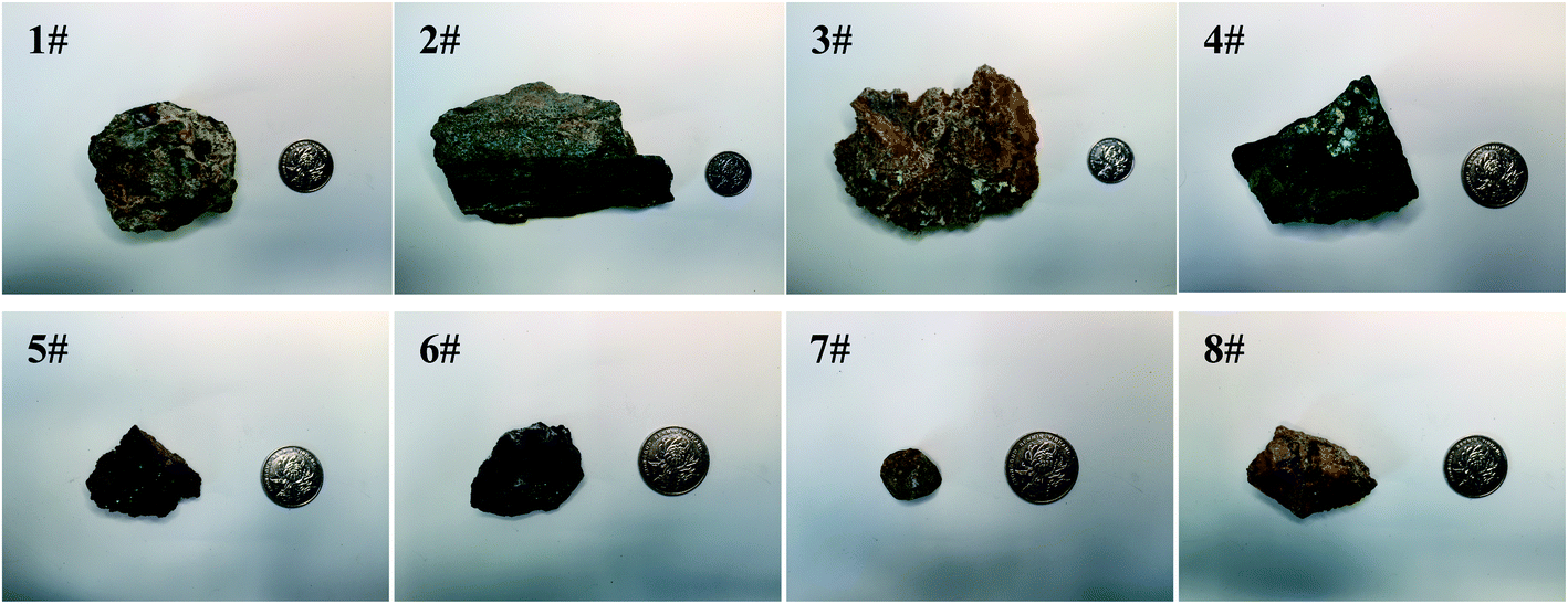 | ||
| Fig. 1 Photos of eight uranium ore samples of different origins. The coin for comparison is 25 mm in diameter. | ||
2.2. Sample digestion and separation
Bulk uranium ore samples were crushed and then powdered with the help of a mortar grinder (Fritsch Pulverisette 2) in advance. For Ce isotopic analysis of reference rock samples and uranium ore samples, approximately 0.5 g of the sample powder was weighed into a PFA vessel. The samples were dissolved with an acid mixture (9 mL of 15 M HNO3 + 6 mL of 20 M HF + 3 mL of 12.4 M HClO4) on a hotplate at 190 °C for 48 h. After evaporating the sample solutions to dryness, they were treated by dissolving with 2 mL of concentrated HNO3 and evaporating to dryness three times. Then the sample was re-dissolved with 2 mL of 6 M HCl at 120 °C and heated to dryness again. After that, the sample was treated overnight at 90 °C with 2 mL of 2.5 M HCl (mixed with 3% H3BO3) to decompose the fluoride gels that may form during the digestion procedure. Finally, the target fraction was re-dissolved in 2 mL of 1 M HNO3 to be prepared for the following separation procedure.As shown in Table 1, compared to the CeO+ technique, which needs sufficient removal of several interferents (Ba, La, Sm, Gd and Dy), the main focus in the Ce+ technique lies on the effective separation of only Ba and La. Therefore, the chemical separation procedure for the Ce+ technique could become relatively simpler and less time-consuming. A two-stage separation procedure (Fig. S1†), which was modified from the methods reported previously,26,28,34–36 was used. Firstly, the sample solution was loaded into a Teflon column filled with 1 g AG 50W-X12 resin, which was pretreated with 4 mL of 1 M HNO3. Main matrix elements were washed out with 8 mL of 5 M HCl. Ba was then eluted with 5 mL of 2 M HNO3, and the light rare earth elements (LREEs) were subsequently eluted with 10 mL of 5 M HNO3. The LREE fraction obtained from this column separation proved to be entirely free of matrix elements, but still contained small amounts of Ba, as an effect of column tailing. Secondly, the collected LREE solution was introduced into the second Teflon column filled with 1 g LN resin, which was pretreated with 4 mL of 10 M HNO3, and the resin top was covered with a porous 30 mm polyethylene filter with the aim of preventing the flotation of resin particles. LREEs(III) were washed out with 6 mL of 10 M HNO3 containing 20 mM KBrO3. In this step, Ce(III) was oxidized to Ce(IV) by the strong oxidizing reagent KBrO3 and thus it remained on the resin. The remaining Ce was then eluted with 10 mL of 6 M HCl solution containing 20 mM H2O2 to ensure effective recovery of Ce. The potential interfering element Ba was effectively removed due to its high decontamination factor (ca. 4 × 10⁶) achieved, and the final fraction enriched in Ce was obtained. The eluted fraction was collected for TIMS analysis. It should be noted that a new column was used for every sample to avoid the risk of cross-contamination. The chemical yield of Ce was about 78% and the total Ce operational blank was less than 60 pg, which was negligible compared to the large quantity of Ce presented in the real samples.
2.3 TIMS analysis
High-purity zone-refined Re filaments with single filament geometry were used. We prepared a FPIE material for the accurate measurement of Ce isotope ratios. Equal weight portions of rhenium (0.5 g, Alfa Aesar 325 mesh) and platinum metal powders (0.5 g, Alfa Aesar 325 mesh) were used. The detailed procedures for the preparation of FPIE have been described elsewhere.44 The FPIE stock was then sintered to the center of the filament and heated at ∼1800 °C using a Thermo Scientific degas unit, with a vacuum of ∼10−7 mbar. The resulting FPIE material was a Pt/Re alloy with a porous structure. The optical and scanning electron microscopy (SEM) images are shown in Fig. S2.†1 μL of the Ce analyte was loaded onto the FPIE filament in 2.5 M HCl, then 1 μL of 0.2 M TaF5 was loaded as an activator after the sample was evaporated to dryness in air. Once the sample was dried, the filament current was gently increased to 2.5 A, and then immediately turned down. In order to enhance the ionization efficiency, great care was taken to load both the sample and activator right on the center of the FPIE. The Ce isotope measurements were performed as Ce+ ions on a Thermo Scientific Triton TIMS at State Key Laboratory of Geological Processes and Mineral Resources, China University of Geosciences. A multi-collector acquisition routine was employed using collectors L4 to H2, and the configuration of the Faraday cups is given in Line 1 of Table 3. The center cup was connected to a 1010 Ω amplifier for collection of the large 140Ce+ ion beam, while all other Faraday cups were connected to conventional 1011 Ω amplifiers. Isobaric contribution from 142Nd+ on 142Ce+ was monitored by measuring 143Nd+ ions in cup H2 during data acquisition, while 137Ba+ and 139La+ ion beams were also collected by cups L3 and L1 to correct the isobaric interferences of 138Ba+ and 138La+ on 138Ce+, respectively. Due to large variations between the relative abundances of Ce isotopes, the peak tailing of the major isotope 140Ce severely interferes with the determination of neighboring minor isotopes. To correct the peak tailing effect, half-mass intensities were measured at magnet settings at −0.5 amu offset (Line 2 of Table 3). The correction of low-mass tailing of the 140Ce peak was performed using the exponential law, which was proposed by Willbold.18 Then the tail-corrected intensities of 138Ce and 136Ce were obtained by subtracting the peak-tail of 140Ce from the measured raw intensities at mass 138 and 136. Afterwards, the mass fractionation correction was performed off-line, and the fractionation factor (β) was determined using the exponential mass fractionation law.
 | (1) |
 | (2) |
| Faraday cup | L4 | L3 | L2 | L1 | C | H1 | H2 | H3 | H4 |
|---|---|---|---|---|---|---|---|---|---|
| Line 1 | 136Ce | 137Ba | 138Ce | 139La | 140Ce | 142Ce | 143Nd | ||
| Line 2 | 135.5 | 136.5 | 137.5 | 138.5 | 139.5 | ||||
| Line 3 | 142Ce | 146 | 142Ce16O |
Each measurement run consisted of 16 blocks with 11 cycles per block, and the integration time for Line 1 and Line 2 of Table 3 were both set to 4.914 s. The amplifier gain of each Faraday cup and the baseline were calibrated prior to Ce isotope measurement every day. After the FPIE filament was kept at ∼1200 °C for ca. 40 minutes, the ion beam was centered and carefully focused until an optimum intensity was reached, then the measurement of Ce isotope ratios could be started when the vacuum in the ion source became better than 1.1 × 10⁻⁷ mbar.
3. Results and discussion
3.1. Enhancing the ionization of Ce+ ions with the FPIE
Ce ionizes as Ce+ and CeO+ ions in the thermal ion source of TIMS, and the values of Ce+/CeO+ would vary significantly with different experimental conditions, including sample-loading techniques, filament material and assembly, temperature of filaments etc. To optimize the conditions for Ce isotope ratio measurement, the ionization behaviors of Ce with the FPIE were investigated. Approximately 1 μg of Ce was loaded on FPIE filaments in 2.5 M HCl together with 1 μL of 0.2 M TaF5. The Faraday cup configuration adopted is shown in Line 3 of Table 3, with all Faraday cup collectors coupled to 1011 Ω resistors, and the integration time was set to 4.914 s. 142Ce+ and 142Ce16O+ ion beams were collected simultaneously by cups L4 and H4, respectively. Increasing damage to the Faraday cups, which can affect the cup efficiency and response linearity, should be taken into account for the routine measurement at high ion beam intensities. Thus the 140Ce+ and 140Ce16O+ ion beams, which might overload the corresponding amplifier, were not collected in the measurement.The filament current was raised at a constant rate of 60 mA min−1, and the data acquisition procedure was carried out until the signals of both 142Ce+ and 142Ce16O+ ions dropped below 10 mV. The 142Ce+ and 142Ce16O+ ion beams increased with the filament temperature at the beginning, and their profiles are shown in Fig. 2a. The peaks of 142Ce16O+ (4.12 V) and 142Ce+ (19.72 V) ion signals appeared at approximately 1050 °C and 1460 °C, respectively. It can be recognized that the integrated intensity of Ce+ was much higher than that of CeO+. Similar trends were observed for the samples containing 2 μg and 0.1 μg Ce as well. In contrast, the phenomenon of the traditional double Re filaments was quite different (Fig. 2b). The peaks of 142Ce16O+ (10.17 V) and 142Ce+ (8.19 V) ion signals located at ca. 1470 °C and 1620 °C, respectively. Notably, CeO+ ionizes more preferentially than Ce+ with traditional double Re filaments. The main reason for the differences was that plenty of CeO+ ions would be broken up by frequent collisions with the porous structure when they migrated through the FPIE material. It was confirmed by the fact that the ratios of Ce+/CeO+ increased with heating of the FPIE filament.
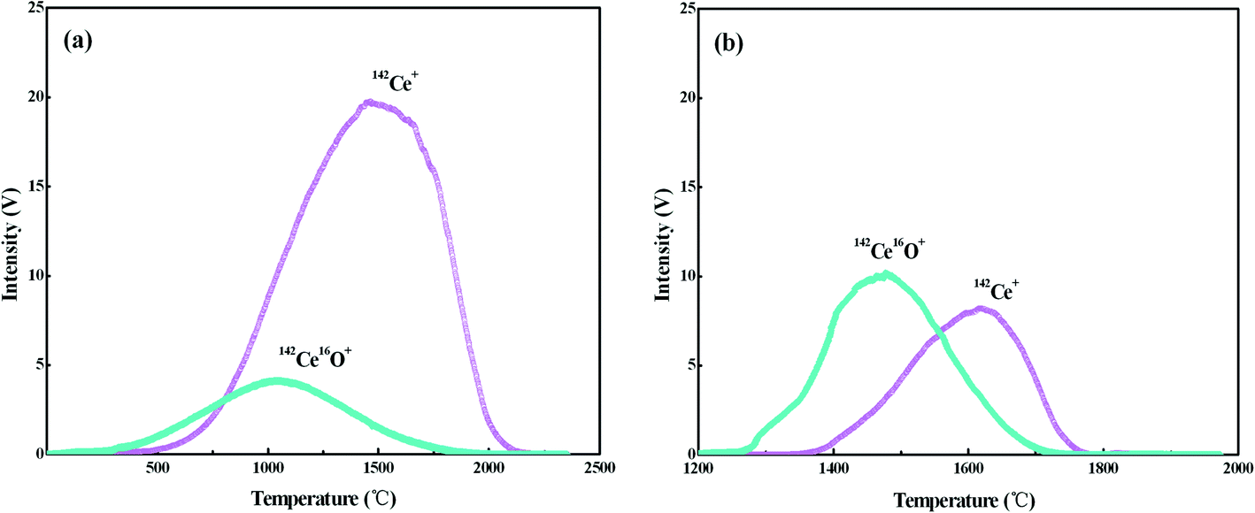 | ||
| Fig. 2 Intensities of 142Ce+ and 142Ce16O+ as a function of the temperature: (a) FPIE filament; (b) traditional double Re filaments. Approximately 1 μg Ce was loaded on the filament, and the Faraday cup configuration is shown in Line 3 of Table 3. | ||
Under the optimized conditions for Ce isotope ratio measurements, further experiments were performed with FPIE filaments loaded with 1 μg Ce. Steady 142Ce+ ion intensities up to ca. 18 V (with a maximum fluctuation of ±5%) could last for over 2–3 h. The remarkable improvement in the stability of the Ce+ ion beam with FPIE was attributed to the combined effect of the porous structure of the FPIE filament. Firstly, the pervasion of the sample solution into the porous structure of the FPIE was achieved by gradually heating the FPIE filament. As a result, the free flow of the sample solution was prevented during TIMS analysis. Therefore, the optimal state of the ion lens was kept unaltered to extract a satisfactory ion beam. Moreover, due to the decrease of the sample surface area, a relatively slow evaporation rate of samples during the heating of the filament was ensured, and a long acquisition time could be obtained, accordingly.
3.2. Isobaric interference of Ba
The isobaric interference of 138Ba on 138Ce is the major challenge for accurate and high-precision Ce isotope measurements with the Ce+ technique. Contributions from interfering elements onto isotopes of interest can be corrected by monitoring another isotope of the interfering species and its known natural abundance. The Ba interference on mass 138 is normally corrected by monitoring 137Ba, for the reason that 137Ba is free of isobaric interferences and its abundance is relatively high. However, as Ba is typically more abundant than Ce in the environment,26 and 138Ba is the most abundant Ba isotope (71.7%), while the abundance of 138Ce is only 0.25%, the presence of even a tiny amount of Ba contamination could result in inaccurate interference correction for 138Ce. In this study, the ion exchange based chemical procedure enabled effective separation of Ba from Ce. Moreover, the FPIE filaments were heated at ∼1200 °C for ca. 40 minutes after sample loading for further eliminating possible residual Ba from the loaded sample. However, these two practices were inadequate for high-precision Ce isotope ratio measurement.Another inherent source of Ba comes from the degassed filaments and materials used for the production of the FPIEs, and it is difficult to overcome the Ba interference even under the conditions of high temperature. We performed the measurements of Ba signals in newly-prepared FPIE filaments after being degassed. The FPIE filaments were prepared with different batches of single Re filaments (n = 5 each batch). 138Ba+ ion beams were collected in the central Faraday cup, which was connected to a 1013 Ω amplifier. Small signals (0.5–0.9 mV) of 138Ba+ were observed in degassed FPIE filaments (Table 4), and they were a little higher than those reported by Willbold,18 the difference may be attributed to different batches of the Re filaments. Such an amount of 138Ba could not be negligible for high-precision measurement of Ce isotope ratios.
| Manufacturer | Batch | 138Ba (μV) | 138Ba* (μV) | Improvement factor |
|---|---|---|---|---|
| Thermo Fisher Scientific | 001-0509444 | 742 | 68 | 10.9 |
| Thermo Fisher Scientific | 003-0702444 | 695 | 87 | 8.0 |
| Thermo Fisher Scientific | 004-2002444 | 838 | 65 | 12.9 |
| Thermo Fisher Scientific | 006-2804444 | 504 | 52 | 9.7 |
In order to further reduce the influence of Ba, we employed TaF5 as an activator to consume Ba by forming BaF+ ions, and the BaF+ peaks at masses 153, 154, 155, 156 and 157 were detected during the preliminary heating procedure (Fig. 3). Since fluorine is a monoisotopic element, the intensities of BaF+ ion beams are proportional to the abundances of Ba isotopes. There was an exception at mass 156, which suffered polyatomic interference of 140Ce16O+ on 137Ba19F+. The appearance of the peak on mass 158, which consisted of 140Ce18O+ and 142Ce16O+, further confirmed the 140Ce16O+ interference on mass 156. The signal at mass 159 was also measured to detect the possible 140Ce19F+ ion beam and no signals were observed. Therefore, the formation of Ce fluoride during the measurement was negligible. The intensity of BaF+ ion beams increased rapidly with increasing FPIE filament temperature, and the Ba+ peaks tended to diminish in the meantime. Blanks of Ba in FPIE filaments were measured again after being loaded with 1 μL of 0.2 M TaF5, and the results showed that 138Ba+ ion beams were significantly reduced by a factor of ca. 10 (Table 4).
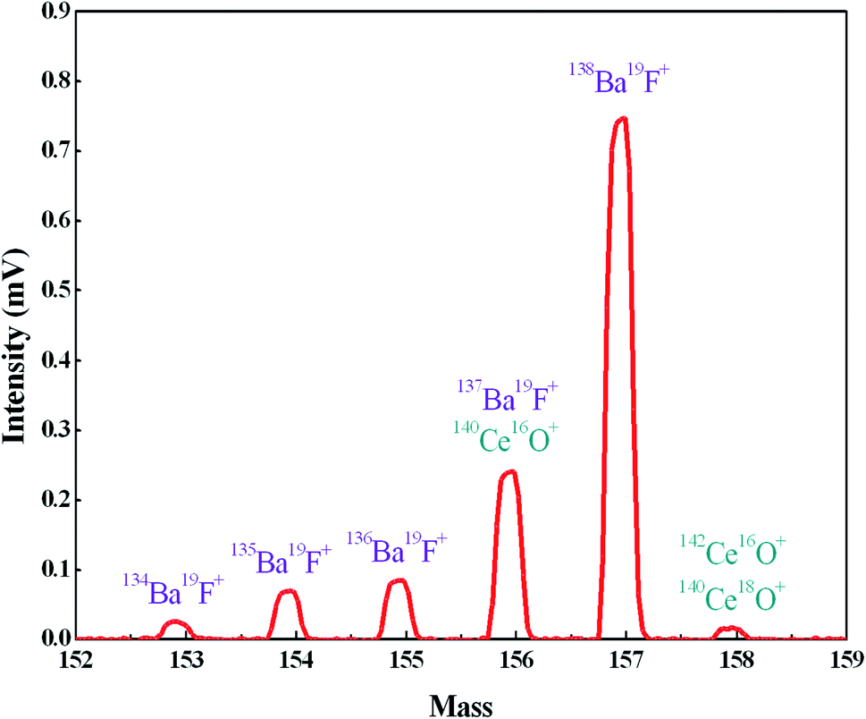 | ||
| Fig. 3 The formation of BaF+ ions at masses 153, 154, 155, 156 and 157 with FPIE filament (T = 1200 °C). | ||
3.3. Selecting the proper reference Ce isotope
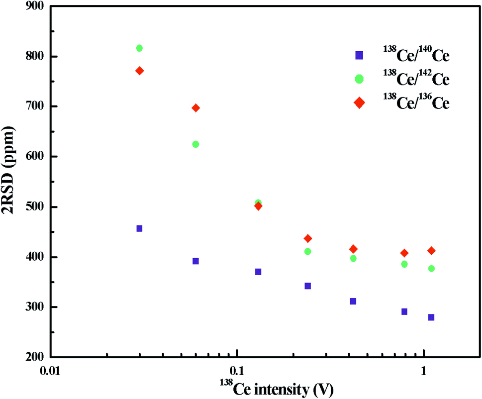
The variation of radiogenic isotope 138Ce in various natural samples is expressed in terms of isotope ratios (the ratios of the 138Ce isotope to a stable Ce isotope). The selection of the reference Ce isotope, therefore, is very important. As shown in Table S1,† the most commonly-used reference isotope was 142Ce. Recently, 136Ce was also proposed to be a new reference isotope.18 However, the accurate determination of 142Ce and 136Ce suffers from isobaric interferences from 142Nd and 136Ba, respectively. Moreover, measurements of these two Ce isotopes are both affected by the peak tailing of the major isotope 140Ce. All these factors further complicate Ce isotope ratio measurements with high-precision. Compared to 142Ce and 136Ce, 140Ce seems to be a possible alternative choice as there is no isobaric interference on 140Ce and the complicated peak tailing correction can be avoided.A number of publications involving only a specific Ce isotope ratio (138Ce/142Ce or 138Ce/136Ce) are available, but no comprehensive comparison on different Ce isotope ratios has been found to date. Therefore, we investigated different Ce isotope ratios of reference rock sample BCR-2 with FPIEs in Ce+ mode. The measurements were performed on large sample loads, i.e. FPIE filaments loaded with 5 μg Ce, and the external precisions (2RSD) of different Ce isotope ratios at various 138Ce beam intensities are illustrated in Fig. 4. All the isotope ratios were corrected with isobaric interferences, and the 138Ce/142Ce and 138Ce/136Ce ratios were tail-corrected as well. It is obvious that the external precisions of all these Ce isotope ratios improved with the increasing of ion beam intensities. The external precisions were similar for 138Ce/142Ce and 138Ce/136Ce ratios, and they were comparable to those determined in Ce+ mode at similar beam sizes.20,31–33 The external precision of the 138Ce/140Ce ratio showed a remarkable improvement, and it was a factor of 1.2–1.8 better compared to those of 138Ce/142Ce and 138Ce/136Ce ratios at the same 138Ce beam intensities. Therefore, the 138Ce/140Ce ratio was regarded as a promising choice to monitor the anomalies of 138Ce in various geological materials.
 | ||
| Fig. 4 External precisions (2RSD) of different Ce isotope ratios as a function of 138Ce+ beam intensity. The measurements were performed in Ce+ mode with FPIE filaments loaded with 5 μg Ce. | ||
The main reason for a better reproducibility achieved by the new target Ce isotope ratio is the avoiding of the isobaric interference correction and the peak-tailing effect. The less data correction work, the better precision of the data would be obtained. To our knowledge, the 138Ce/140Ce ratios for JMC-304 and the chondritic uniform reservoir (CHUR) were not certified, thus we obtained them using the certified 138Ce/142Ce values and a constant 140Ce/142Ce value of 7.941.8,24,25 With (138Ce/142Ce)JMC-304 = 0.0225762–0.0225799 (ref. 25, 29, 38 and 52–56) and (138Ce/142Ce)CHUR = 0.0225652,16,19,26,57 the 138Ce/140Ce ratio values were calculated to be 0.002842992–0.002843458 for JMC-304 and 0.002841607 for CHUR, respectively.
Nearly all Ce isotopic data in the literature have been reported in terms of 138Ce/142Ce or 138Ce/136Ce, thus it is inconvenient for a direct comparison. Therefore, Ce isotope ratios were translated to the ε notation in our discussion. It is defined as
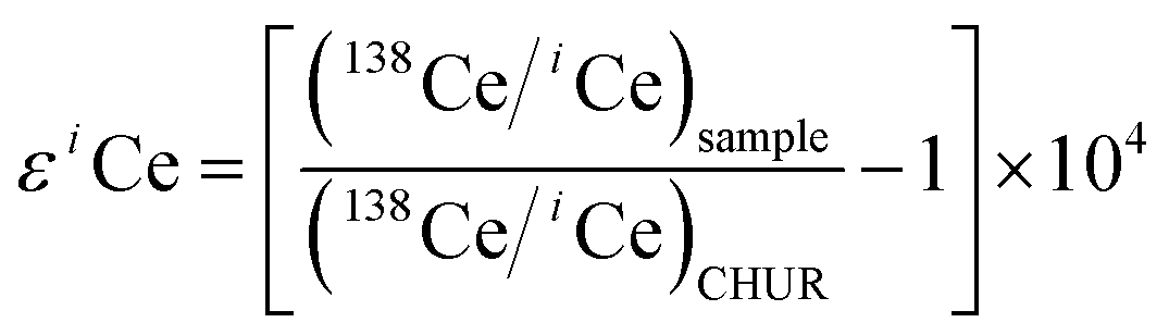 | (3) |
3.4. Using diverse ohm amplifiers for the measurement of the 138Ce/140Ce ratio
For high-precision measurement of the 138Ce/140Ce ratio, 138Ce and 140Ce ion beams should be collected simultaneously. The 140Ce isotope is much more abundant compared to the 138Ce isotope (88.45 at% versus 0.25 at%), thus measuring ion beams over a large dynamic range is needed. This issue is partly overcome on new generation mass spectrometers with the development of amplifiers with diverse ohm resistances (1010 Ω, 1012 Ω and 1013 Ω). The use of high ohm resistor amplifiers (1012 Ω or 1013 Ω) is an option for the measurement of low beam intensities with high precision, and they can be used alone, or in combination with conventional 1010 Ω and/or 1011 Ω amplifiers.45–50,58–60 While the 1012 Ω resistors provide a 10 times higher gain of the amplifiers, the Johnson noise of the resistor only increases by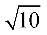 , thus resulting in an approximately 3-fold theoretical improvement in the signal-to-noise ratio. Similarly, the theoretical improvement obtained in the signal-to-noise ratio is 10 times for 1013 Ω amplifiers. The gain calibration for each resistor was performed prior to the mass spectrometric measurements each day. Gain calibration factors for the 1010 Ω, 1011 Ω and 1012 Ω resistors were determined using the regular software controlled gain procedure, which uses a stable reference current (3.33333 V). However, this procedure is not implemented for 1013 Ω resistors, because this used reference current will overload the 1013 Ω resistors. Instead, gain calibration factors for the 1013 Ω resistors were determined with the calibration protocol described by Kimura et al.,61 and then manually updated in the system table. Baselines were measured in a 15 min routine (900 cycles of 1s integration) before and after the Ce isotopic measurements. The gain corrected baseline noise values for 1011 Ω, 1012 Ω and 1013 Ω amplifiers were ∼9.7 μV, ∼2.2 μV and ∼0.8 μV (1SD), respectively.
For comparison, Ce isotope ratio analysis with FPIEs was performed using different combinations of amplifiers (Table 5) in Ce+ mode. All analyses consisted of 176 cycles of 8.389 s integration each, and 2 μg Ce standard (JMC-304) was loaded and measured. The 140Ce+ intensities were kept at about 280 V. For convenient comparison, gain corrected intensities relative to the default 1011 Ω amplifiers were reported in this paper.
| Faraday cup | L4 | L3 | L2 | L1 | C | H1 | H2 |
|---|---|---|---|---|---|---|---|
| Ions required | 136Ce | 137Ba | 138Ce | 139La | 140Ce | 142Ce | 143Nd |
| Amp 1 | 1011 Ω | 1011 Ω | 1011 Ω | 1011 Ω | 1010 Ω | 1011 Ω | 1011 Ω |
| Amp 2 | 1011 Ω | 1011 Ω | 1012 Ω | 1011 Ω | 1010 Ω | 1011 Ω | 1011 Ω |
| Amp 3 | 1011 Ω | 1012 Ω | 1011 Ω | 1011 Ω | 1010 Ω | 1011 Ω | 1011 Ω |
| Amp 4 | 1011 Ω | 1013 Ω | 1011 Ω | 1011 Ω | 1010 Ω | 1011 Ω | 1011 Ω |
| Amp 5 | 1011 Ω | 1013 Ω | 1012 Ω | 1011 Ω | 1010 Ω | 1011 Ω | 1011 Ω |
The measured 138Ce/140Ce ratios for 2 μg JMC-304 using different combinations of amplifiers with the FPIE method in Ce+ mode are illustrated in Fig. 5, wherein the error bars represent the internal precision (2SE) of an individual sample. Firstly, a combination of 1010 Ω and 1011 Ω amplifiers was used where the 140Ce+ beam was measured on a 1010 Ω amplifier and the other isotopes on 1011 Ω amplifiers. The external precision (2RSD) of 138Ce/140Ce ratios obtained was 312 ppm, and it was improved to 281 ppm and 178 ppm with 1012 Ω amplifiers connecting to the Faraday cups L2 and L3, respectively. These improvements are mainly explained by the high signal-to-noise ratio of high ohm amplifiers. Compared to 138Ce, the beam intensity of the interference monitor 137Ba was extremely low (∼10 μV), therefore the application of a high ohm amplifier to collect 137Ba resulted in a better analytical precision. In spite of the improvements, none of them could fulfill the requirements for Ce isotope ratio measurement in nuclear forensic research. Furthermore, a 1013 Ω amplifier was employed to collect the 137Ba ion beam, meanwhile 1011 Ω and 1012 Ω amplifiers were employed on 138Ce, successively. The weighted average 138Ce/140Ce ratios were 0.00284305 ± 14 (2SD, n = 10) and 0.00284296 ± 10 (2SD, n = 10) for the 1013–1011–1010 Ω and 1013–1012–1010 Ω amplifier combinations, respectively. The consistency of the experimental data with the reference value of JMC-304 (0.002842992–0.002843458) demonstrated the accuracy of the newly-developed method. Moreover, it suggested that the contribution of the operational blank for Ce isotope analysis is negligible. The obtained reproducibility of 138Ce/140Ce ratios for the 1013–1012–1010 Ω combination was 36 ppm, showing a factor of ca. 10 improvement compared to that obtained using solely 1011 Ω amplifiers on 137Ba and 138Ce, and it was even comparable with those obtained using the CeO+ technique for similar Ce loading levels.12,16–18,20–28 The reproducibility of 138Ce/140Ce ratios using the 1013–1011–1010 Ω combination (2RSD of 48 ppm, n = 10) was slightly worse compared to that obtained using the 1013–1012–1010 Ω combination. However, they were both adequate for resolving variations of 138Ce/140Ce ratios within the eighth decimal place for geological samples.
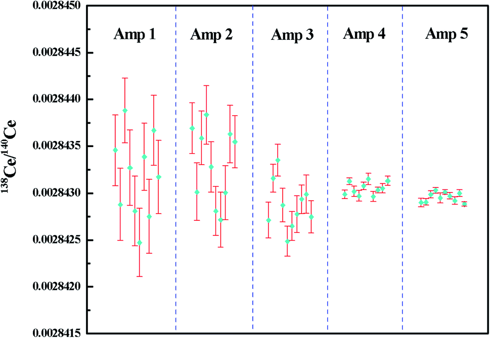 | ||
| Fig. 5 138Ce/140Ce ratios measured for 2 μg JMC-304 using different combinations of amplifiers with the FPIE method as Ce+. The error bars in each measurement are given in 2SE. Amp 1–5 refer to different combinations of amplifiers in the Faraday cup configuration listed in Table 5. | ||
With the employment of TaF5 as an activator, the 137Ba+ ion beam was consequently suppressed to levels of ∼10 μV, corresponding to 138Ba/138Ce ≈ 0.00008 as the 138Ce+ ion beam could reach ca. 80 mV on 2 μg loads with FPIEs. The baseline noise on the 1013 Ω feedback resistors was measured to be ca. 0.8 μV (1 SD), which introduced ca. 8% bias for the 137Ba and 138Ba signals. As the 138Ba/138Ce ratio was about 0.00008, the bias introduced for this ratio from the correction of 138Ba was ca. 7 ppm, which was within the external precision (2RSD = 36 ppm) of 138Ce/140Ce ratios using the 1013–1012–1010 Ω combination of current amplifiers. Therefore, with the application of a 1013 Ω resistor for the 137Ba signal detection, accurate interference correction of 138Ba on 138Ce was possible, and high-precision Ce isotope ratios with the Ce+ technique could be obtained.
Idle time defines the waiting time prior to measuring the new line in the cup configuration table during dynamic measurements, and the majority of the idle time is needed for decay of the current amplifier. Compared to conventional 1011 Ω amplifiers, the idle time of high ohm amplifiers is much longer for their slower response time, accordingly, a longer data acquisition time is required. Therefore, the use of high ohm amplifiers requires a more stable ion beam to obtain high-precision Ce isotope ratios. Typically, the 140Ce+ ion beam could reach 280 V after being fully focused on 2 μg loads with FPIEs, and it could last for more than 200 minutes, which was superior to that when loading with conventional Re filaments. The excellent stability of Ce+ ion beams obtained with FPIEs supported our method to be applied in high-precision measurements of Ce isotope ratios.
Recently, Bonnand et al.36 determined Ce isotope ratios using diverse ohm amplifiers with the CeO+ technique, and they measured the 136Ce16O+, 138Ce16O+ and 142Ce16O+ ions together with the interference oxide ions. As the number of interferences collected was limited, the less abundant 134Ba (2.4%) was used instead of 137Ba (11.2%) as a Ba interference monitor. In our work, the combination of diverse ohm amplifiers was applied for Ce measurement as Ce+ ions. By using the high ohm amplifier, the small signal of 137Ba (which has no isobaric interference) could be directly detected, thus the interference of a trace amount of 138Ba could be corrected more precisely.
3.5. Ce isotope analysis of reference rock samples and uranium ore samples
Replicate analysis was done for five reference rock samples with different sample matrices to evaluate the reproducibility of the newly-developed TIMS method. The amount of Ce introduced into the mass spectrometer for a single analysis was typically 2 μg Ce, which was sufficient to obtain a large and stable Ce+ ion beam. The results are shown in Table 6 and Fig. 6, and the bars below the εCe values of reference rock samples represent the reported εCe values in Table 6. The external precisions of 138Ce/142Ce and 138Ce/136Ce ratios were comparable to those previously reported in CeO+ mode (Table S1†). By using our method, the external precision of the 138Ce/140Ce ratio was slightly better than those of 138Ce/142Ce and 138Ce/136Ce ratios. Moreover, the εCe values obtained for most reference rock samples were in good agreement with literature values, indicating high reliability of our method in geological samples.| Sample | 138Ce/142Ce | 138Ce/136Ce | 138Ce/140Ce | ε(138Ce/140Ce)CHUR | Reported ε(138Ce/142Ce)CHUR |
|---|---|---|---|---|---|
| BCR-2 | 0.0225739 | 1.33729 | 0.00284173 | +0.43 | |
| 0.0225714 | 1.33718 | 0.00284166 | +0.19 | ||
| 0.0225711 | 1.33721 | 0.00284162 | +0.05 | ||
| 0.0225728 | 1.33742 | 0.00284177 | +0.57 | ||
| 0.0225745 | 1.33728 | 0.00284185 | +0.85 | ||
| 0.0225716 | 1.33734 | 0.00284171 | +0.36 | ||
| Mean ± 2SD | 0.0225726 ± 14 | 1.33729 ± 9 | 0.00284172 ± 16 | +0.41 ± 0.56 | 0.08–0.79 (ref. 12, 19, 27 and 28) |
| JA-2 | 0.0225701 | 1.33704 | 0.00284147 | −0.48 | |
| 0.0225710 | 1.33717 | 0.00284153 | −0.27 | ||
| 0.0225715 | 1.33711 | 0.00284158 | −0.09 | ||
| 0.0225691 | 1.33709 | 0.00284141 | −0.69 | ||
| 0.0225727 | 1.33727 | 0.00284150 | −0.37 | ||
| 0.0225719 | 1.33718 | 0.00284156 | −0.16 | ||
| Mean ± 2SD | 0.0225711 ± 13 | 1.33714 ± 8 | 0.00284151 ± 12 | −0.34 ± 0.42 | −0.19 to −0.30 (ref. 19) |
| JB-3 | 0.0225673 | 1.33694 | 0.00284103 | −2.03 | |
| 0.0225684 | 1.33697 | 0.00284117 | −1.54 | ||
| 0.0225696 | 1.33702 | 0.00284125 | −1.26 | ||
| 0.0225668 | 1.33696 | 0.00284109 | −1.82 | ||
| 0.0225689 | 1.33699 | 0.00284122 | −1.36 | ||
| 0.0225677 | 1.33712 | 0.00284119 | −1.47 | ||
| Mean ± 2SD | 0.0225681 ± 11 | 1.33700 ± 6 | 0.00284116 ± 9 | −1.58 ± 0.32 | −1.22 to −1.96 (ref. 2, 16, 19 and 26) |
| JG-1 | 0.0225741 | 1.33731 | 0.00284202 | +1.45 | |
| 0.0225749 | 1.33737 | 0.00284207 | +1.63 | ||
| 0.0225762 | 1.33746 | 0.00284199 | +1.35 | ||
| 0.0225737 | 1.33725 | 0.00284186 | +0.89 | ||
| 0.0225721 | 1.33727 | 0.00284179 | +0.64 | ||
| 0.0225744 | 1.33736 | 0.00284195 | +1.20 | ||
| Mean ± 2SD | 0.0225742 ± 14 | 1.33734 ± 8 | 0.00284195 ± 13 | +1.20 ± 0.46 | 0.05–0.52 (ref. 19) |
| JR-1 | 0.0225698 | 1.33711 | 0.00284141 | −0.69 | |
| 0.0225692 | 1.33705 | 0.00284125 | −1.26 | ||
| 0.0225674 | 1.33698 | 0.00284115 | −1.61 | ||
| 0.0225721 | 1.33704 | 0.00284130 | −1.08 | ||
| 0.0225683 | 1.33682 | 0.00284118 | −1.50 | ||
| 0.0225706 | 1.33695 | 0.00284122 | −1.36 | ||
| Mean ± 2SD | 0.0225696 ± 17 | 1.33699 ± 10 | 0.00284125 ± 19 | −1.25 ± 0.67 | −0.6 to −1.47 (ref. 2 and 23) |
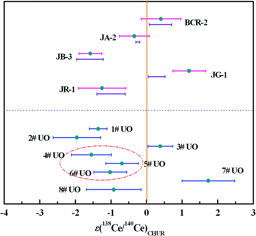 | ||
| Fig. 6 The εCe values of reference rock samples and uranium ore samples. The bars below the εCe values of reference rock samples represent the reported εCe values in Table 6, and the vertical line represents εCe = 0. | ||
In addition to multiple analysis of reference rock samples, further Ce isotope measurements were performed for eight uranium ore samples (1#–8#) to test the developed method for nuclear forensics purposes. The results are depicted in Fig. 6 and presented in Table 7 and Table S2.† Clear differences, ranging from −3 to +3, in the εCe values of the uranium ores can be observed. The εCe value of the 4# uranium ore sample was considered to overlap within error with those of 5# and 6# samples originating from the same uranium mine from Congo, while a similar phenomenon was observed for 1# and 2# uranium ore samples mined from the USA. Meanwhile, the εCe values of 3#, 7# and 8# uranium ore samples originating from different countries shared no overlap with each other. These results indicated the Ce isotopic composition might act as an informative clue for assessing the origin of uranium ores and it would be helpful to establish a worldwide database of Ce isotopic composition with high precision to serve nuclear forensics purposes.
| Sample | Ce concentration (ppm) | ε(138Ce/140Ce)CHUR | Mean ± 2SD |
|---|---|---|---|
| a Ce concentrations of uranium ore samples were measured by ICP-MS (Agilent 7700x). | |||
| 1# UO | 964 | −1.36, −1.54, −1.26, −1.19, −1.43, −1.36 | −1.36 ± 0.25 |
| 2# UO | 72.9 | −1.57, −2.03, −2.42, −1.64, −1.92, −2.21 | −1.96 ± 0.67 |
| 3# UO | 19.1 | +0.43, +0.33, +0.71, +0.36, +0.29, +0.22 | +0.39 ± 0.35 |
| 4# UO | 2.04 | −1.54, −1.89, −1.26, −1.82, −1.64, −1.19 | −1.55 ± 0.56 |
| 5# UO | 141 | −0.45, −0.83, −0.90, −0.38, −0.69, −0.90 | −0.69 ± 0.46 |
| 6# UO | 77.6 | −0.76, −1.04, −0.83, −0.90, −1.365, −1.22 | −1.02 ± 0.46 |
| 7# UO | 127 | +1.95, +2.16, +1.42, +1.24, +2.09, +1.59 | +1.74 ± 0.74 |
| 8# UO | 92.8 | −1.01, −1.47, −0.76, −0.38, −1.22, −0.69 | −0.92 ± 0.77 |
However, we also observed that there were overlaps of the εCe values of some uranium ore samples originating from different countries. Consequently, the Ce isotopic composition should not be regarded as an exclusive proof in origin assessment, instead, it was supposed to perform better by the combination with other characteristic information (such as Nd isotopic composition, REE concentrations etc.) to reliably trace the origin of unknown nuclear materials or significantly narrow down to a few possibilities.
4. Conclusions
A novel method has been developed and validated for the measurement of Ce isotope ratios as Ce+ ions in geological and uranium ore samples by TIMS. Ce was oxidized and effectively separated from interfering matrix components with an oxidation separation procedure. The newly-developed FPIE was used for TIMS measurement and Ce was observed to ionize more efficiently as Ce+ ions than CeO+ ions compared to the methods using traditional double Re filaments. The isobaric interference of Ba was effectively suppressed by one order of magnitude with the employment of TaF5 as an activator, and it further ensured the high-precision Ce isotope ratio analysis with the Ce+ technique. 140Ce was found to be a promising reference isotope to monitor the anomalies of 138Ce in geological materials. The external precision of the 138Ce/140Ce ratio showed a remarkable improvement, and it was a factor of 1.2–1.8 better compared to those of 138Ce/142Ce and 138Ce/136Ce ratios at the same beam intensities. For the analysis of Ce isotopic ratios as Ce+ ions, the performances of diverse ohm current amplifiers were investigated and an optimized combination of current amplifiers was suggested. With the 1013–1012–1010 Ω amplifier combination, the obtained weighted 138Ce/140Ce ratio for a reference material (JMC-304) containing 2 μg Ce was 0.00284296 ± 10 (2SD, n = 10). The reproducibility of the 138Ce/140Ce isotope ratio was a factor of ca. 10 better compared to that obtained using the previously published Ce+ techniques. Furthermore, the εCe values of the reference rock samples of this study agreed well with those previously reported, indicating the reliability of the newly-developed method. This method was used for the determination of the 138Ce/140Ce ratios in uranium ores of world-wide origin. The results showed significant variations between different samples, and the obtained analytical precision successfully met the requirements for sample source identification.Conflicts of interest
There are no conflicts to declare.Acknowledgements
This work was supported by the National Natural Science Foundation of China (No. 11805172 and 11605172) and partly supported by the Science Challenge Project (No. TZ2016004).References
- S. Nakai, H. Shimizu and A. Masuda, Nature, 1986, 320, 433–435 CrossRef CAS.
- T. Tanaka, H. Shimizu, Y. Kawata and A. Masuda, Nature, 1987, 327, 113–117 CrossRef CAS.
- A. P. Dickin, Nature, 1988, 333, 403–404 CrossRef CAS.
- N. Bellot, M. Boyet, R. Doucelance, P. Bonnand, I. P. Savov, T. Plank and T. Elliott, Chem. Geol., 2018, 500, 46–63 CrossRef CAS.
- M. Tanimizu and T. Tanaka, Geochim. Cosmochim. Acta, 2002, 66, 4007–4014 CrossRef CAS.
- R. Nakada, Y. Takahashi and M. Tanimizu, Geochim. Cosmochim. Acta, 2016, 181, 89–100 CrossRef CAS.
- H. J. W. De Baar, M. P. Bacon and P. G. Brewer, Nature, 1983, 301, 324–327 CrossRef CAS.
- M. Tanimizu, Phys. Rev. C: Nucl. Phys., 2000, 62, 017601 CrossRef.
- H. Shimizu, M. Amano and A. Masuda, Geology, 1991, 19, 369–371 CrossRef CAS.
- A. Bouvier, J. D. Vervoort and P. J. Patchett, Earth Planet. Sci. Lett., 2008, 273, 48–57 CrossRef CAS.
- H. Tazoe, H. Obata and T. Gamo, Geochem., Geophys., Geosyst., 2011, 12, 04004 CrossRef.
- R. Doucelance, N. Bellot, M. Boyet, T. Hammouda and C. Bosq, Earth Planet. Sci. Lett., 2014, 407, 175–186 CrossRef CAS.
- E. Keegan, S. Richter, I. Kelly, H. Wong, P. Gadd, H. Kuehn and A. Alonso-Munoz, Appl. Geochem., 2008, 23, 765–777 CrossRef CAS.
- S. H. Han, Z. Varga, J. Krajkó, M. Wallenius, K. Song and K. Mayer, J. Anal. At. Spectrom., 2013, 28, 1919–1925 RSC.
- Z. Varga, M. Wallenius and K. Mayer, Radiochim. Acta, 2010, 98, 771–778 CAS.
- H. Tazoe, H. Obata, H. Amakawa, Y. Nozaki and T. Gamo, Mar. Chem., 2007, 103, 1–14 CrossRef CAS.
- A. Makishima and E. Nakamura, Chem. Geol., 1991, 94, 1–11 CrossRef CAS.
- M. Willbold, J. Anal. At. Spectrom., 2007, 22, 1364–1372 RSC.
- C. Schnabel, C. Münker and E. Strub, J. Anal. At. Spectrom., 2017, 32, 2360–2370 RSC.
- T. Tanaka and A. Masuda, Nature, 1982, 300, 515–518 CrossRef CAS.
- H. Shimizu, T. Tanaka and A. Masuda, Nature, 1984, 307, 251–252 CrossRef CAS.
- N. Nakamura, M. Tatsumoto and K. R. Ludwig, J. Geophys. Res., 1984, 89, 438–444 CrossRef CAS.
- H. Amakawa, Y. Nozaki and A. Masuda, Chem. Geol., 1996, 131, 183–195 CrossRef CAS.
- M. Tanimizu, T. Hayashi and T. Tanaka, J. Mass Spectrom. Soc. Jpn., 2004, 52, 177–181 CrossRef CAS.
- T. Hayashi, M. Tanimizu and T. Tanaka, Precambrian Res., 2004, 135, 345–357 CrossRef CAS.
- H. Tazoe, H. Obata and T. Gamo, J. Anal. At. Spectrom., 2007, 22, 616–622 RSC.
- N. Bellot, M. Boyet, R. Doucelance, C. Pin, C. Chauvel and D. Auclair, Geochim. Cosmochim. Acta, 2015, 168, 261–279 CrossRef CAS.
- M. Willig and A. Stracke, Chem. Geol., 2018, 476, 119–129 CrossRef CAS.
- H. Shimizu, H. Sawatari, Y. Kawata, P. N. Dunkley and A. Masuda, Contrib. Mineral. Petrol., 1992, 110, 242–252 CrossRef CAS.
- Y. K. Xiao, W. G. Liu and Y. M. Zhou, Int. J. Mass Spectrom. Ion Processes, 1994, 136, 181–189 CrossRef CAS.
- T. L. Chang, Q. Y. Qian, M. T. Zhao, J. Wang and Q. Y. Lang, Int. J. Mass Spectrom. Ion Processes, 1995, 142, 125–131 CrossRef CAS.
- A. Makishima and A. Masuda, Chem. Geol., 1994, 118, 1–8 CrossRef CAS.
- M. Rehkämper, M. Gärtner and S. L. Goldstein, Chem. Geol., 1996, 129, 201–208 CrossRef.
- C. F. Li, X. C. Wang, Y. L. Li, Z. Y. Chu, J. H. Guo and X. H. Li, J. Anal. At. Spectrom., 2015, 30, 895–902 RSC.
- S. Kagami and T. Yokoyama, Anal. Chim. Acta, 2016, 937, 151–159 CrossRef CAS PubMed.
- P. Bonnand, C. Israel, M. Boyet, R. Doucelance and D. Auclair, J. Anal. At. Spectrom., 2019, 34, 504–516 RSC.
- C. F. Li, F. K. Chen and X. H. Li, Int. J. Mass Spectrom., 2007, 266, 34–41 CrossRef CAS.
- A. Masuda, H. Shimizu, S. Nakai, A. Makishima and S. Lahti, Earth Planet. Sci. Lett., 1988, 89, 316–322 CrossRef CAS.
- M. G. Watrous, J. E. Delmore and M. L. Stone, Int. J. Mass Spectrom., 2010, 296, 21–24 CrossRef CAS.
- M. G. Watrous and J. E. Delmore, Int. J. Mass Spectrom., 2011, 303, 1–5 CrossRef CAS.
- M. L. Baruzzini, H. L. Hall, K. J. Spencer and F. E. Stanley, Int. J. Mass Spectrom., 2018, 430, 57–62 CrossRef CAS.
- M. L. Baruzzini, H. L. Hall, M. G. Watrous, K. J. Spencer and F. E. Stanley, Int. J. Mass Spectrom., 2017, 412, 8–13 CrossRef CAS.
- F. E. Stanley, K. J. Spencer, D. S. Schwartz, M. G. Watrous and J. E. Delmore, J. Radioanal. Nucl. Chem., 2014, 299, 1447–1452 CrossRef CAS.
- X. P. Shao, W. T. Bu, K. M. Long, L. Tang, X. M. Liu, H. Yan and F. H Hao, Spectrochim. Acta, Part B, 2019, 159, 105656 CrossRef CAS.
- J. M. Koornneef, C. Bouman, J. B. Schwieters and G. R. Davies, J. Anal. At. Spectrom., 2013, 28, 749–754 RSC.
- J. M. Koornneef, C. Bouman, J. B. Schwieters and G. R. Davies, Anal. Chim. Acta, 2014, 819, 49–55 CrossRef CAS PubMed.
- A. Trinquier and P. Komander, J. Radioanal. Nucl. Chem., 2016, 307, 1927–1932 CrossRef CAS.
- A. V. Quadt, J. F. Wotzlaw, Y. Buret, S. J. E. Large, I. Peytcheva and A. Trinquier, J. Anal. At. Spectrom., 2016, 31, 658–665 RSC.
- M. Pfeifer, N. S. Lloyd, S. T. M. Peters, F. Wombacher, B. M. Elfers, T. Schulze and C. Münker, J. Anal. At. Spectrom., 2017, 32, 130–143 RSC.
- N. S. Lloyd, A. Y. Sadekov and S. Misra, Rapid Commun. Mass Spectrom., 2018, 32, 9–18 CrossRef CAS PubMed.
- A. Makishima, H. Shimizu and A. Masuda, J. Mass Spectrom. Soc. Jpn., 1987, 35, 64–72 CrossRef CAS.
- H. Shimizu, S. Nakai, S. Tasaki, A. Masuda, D. Bridgewater, A. P. Nutman and H. Baadsgaard, Earth Planet. Sci. Lett., 1988, 91, 159–169 CrossRef CAS.
- H. Shimizu, N. Umemoto, A. Masuda and P. W. U. Appel, Geochim. Cosmochim. Acta, 1990, 54, 1147–1154 CrossRef CAS.
- H. Amakawa, J. Ingri, A. Masuda and H. Shimizu, Earth Planet. Sci. Lett., 1991, 105, 554–565 CrossRef CAS.
- H. Shimizu, S.-G. Lee, A. Masuda and M. Adachi, Geochem. J., 1996, 30, 57–69 CrossRef CAS.
- S.-G. Lee, A. Masuda, H. Shimizu and Y.-S. Song, Geochem. J., 2001, 35, 175–187 CrossRef CAS.
- A. Makishima and A. Masuda, Chem. Geol., 1993, 106, 197–205 CrossRef CAS.
- D. Wielandt and M. Bizzarro, J. Anal. At. Spectrom., 2011, 26, 366–377 RSC.
- A. Makishima and E. Nakamura, J. Anal. At. Spectrom., 2012, 27, 891–895 RSC.
- T. Schulz, C. Muenker and S. T. M. Peters, Earth Planet. Sci. Lett., 2013, 362, 246–257 CrossRef CAS.
- J. I. Kimura, Q. Chang, N. Kanazawa, S. Sasaki and B. S. Vaglarov, J. Anal. At. Spectrom., 2016, 31, 790–800 RSC.
Footnote |
| † Electronic supplementary information (ESI) available. See DOI: 10.1039/c9ja00420c |
| This journal is © The Royal Society of Chemistry 2020 |