 Open Access Article
Designed additive suppresses interpenetration in IRMOF-10†
Cassidy A. Carey b,
Leila M. Foroughi
 a and
Adam J. Matzger
 *ab
*ab
aDepartment of Chemistry, University of Michigan, 930 North University Avenue, Ann Arbor, Michigan 48109, USA. E-mail: matzger@umich.edu
bMacromolecular Science and Engineering Program, University of Michigan, Ann Arbor, MI 48019, USA
First published on 12th August 2024
Abstract
IRMOF-10, derived from biphenyl-4,4′-dicarboxylic acid and zinc, is a prototype for an open cubic structure prone to interpenetration. Interpenetration can compromise MOF pore volume and surface area which drives the need to develop strategies to synthesize non-interpenetrated MOFs. In this work, an additive design strategy was employed to suppress interpenetration of IRMOF-10. The presence of the additive during traditional solvothermal synthesis yielded an activated material with the highest surface area reported to date and enabled the determination of the single crystal structure. In situ monitoring of the nucleation of crystals under polarized light provided insights into the mechanism behind interpenetration in the IRMOF-9/10 system. This work provides a roadmap to suppress interpenetration more generically in other MOFs and achieve improved surface areas and pore volumes for this prominent class of porous sorbents.
The seminal paper on the concept of isoreticular metal–organic frameworks (IRMOFs) was published over 20 years ago.1a The impact of this paper for guiding the field in how to achieve functional group modifications and rational changes in lattice parameters is hard to overstate. Based on the structure of MOF-5, this work introduced compounds including IRMOF-3 (the amine derivative of MOF-5), IRMOF-8 (featuring an expanded cage based on 2,6-napthalenedicarboxylate), and IRMOF-10 (based on biphenyl-4,4′-dicarboxylate) that have launched thousands of investigations. This study arose during the early days of porous MOFs and therefore before expectations were calibrated in terms of what surface areas should be achievable for these materials. In the case of IRMOF-8, the scientific expectation would be that it possesses a higher surface area than the smaller pore analog MOF-5 (3400 m2 g−1).1b However, subsequent experiments found surface area on the order of 1466 m2 g−1.2 This dramatic discrepancy was later ascribed to the occurrence of interpenetration that was not apparent in the original crystal structure.3,4 Subsequent studies were able to produce pristine IRMOF-8 with a surface area of 4461 m2 g−1, which is well in line with expectations.5 The mystery of IRMOF-10, an even greater expansion of the MOF-5 lattice, is the subject of this contribution.
The reaction of zinc nitrate with biphenyl-4,4′-dicarboxylic acid has been reported to yield a doubly interpenetrated framework structure, IRMOF-9, as colorless rectangular crystals in an orthorhombic space group (Pnnm). By carrying out the reaction under higher dilution, small crystals postulated to be non-interpenetrated IRMOF-10 were obtained.1a These crystals, however, were not suitable for single-crystal X-ray diffraction nor was porosity measured. Interpenetration or catenation6 arises when one framework is present within another and no covalent bonds connect these frameworks. This commonly arises with certain network topologies (including the ubiquitous primitive cubic (pcu) topology that is the basis of the IRMOF series) wherein each separate framework is structurally identical, but the degree of interpenetration can vary.7,8 While interpenetration has been shown to improve the structural stability of MOFs9 it is generally undesirable because additional frameworks within the voids leads to decreased accessible pore volume and results in diminution of guest storage capacity.8,10
Interpenetration in pcu MOFs has been extensively studied and there have been several attempts to yield non-interpenetrated materials including variation of reaction temperature and concentration,5,11 functionalization,12,13 and solvent-based density separation.14 Recently, Feldblyum and coworkers introduced a method to deinterpenetrate IRMOF-9, yielding IRMOF-10 with a surface area of 1778 m2 g−1.15 Experimental efforts aside, theory has predicted the surface area (5000 m2 g−1, see ESI†),16–18 and gas storage potential of hypothetical pristine IRMOF-10.19,20 In spite of establishing new methodologies to suppress interpenetration in IRMOF-10, experimentally reported surface areas are still less than half of the surface area value expected for the non-interpenetrated structure. Herein we demonstrate a strategy to suppress interpenetration within the IRMOF-9/IRMOF-10 system to yield improved BET surface area and non-interpenetrated phases of sufficient size and quality to determine the structure via single crystal X-ray diffraction.
We hypothesized that an additive designed to interact with the specific metrics of the IRMOF-10 lattice would slow the formation of an interpenetrating framework. An additive was designed by employing a geometric design strategy to suppress interpenetration within the IRMOF-10 framework during synthesis. This was achieved by incorporation of a bent aromatic dicarboxylic acid additives with a coordinating distance matching that that of two diagonally situated Zn4O clusters across an IRMOF-10 pore window. A similar approach was previously shown by Kuthuru et al. to result in different morphologies of MOF-5 without changing the original phase.21,22 Herein, an additive (structure in Fig. 1a) was designed computationally such that the coordinating C–C distance, that is, the distance between the carbons of the carboxylic acids (Fig. 1a), matches the distance between two diagonally situated Zn4O clusters across the pore window (Fig. 1b) in the simulated structure IRMOF-10 (see ESI† for details). The additive (5′′-bromo-[1,1′:4′,1′′:3′′,1′′′:4′′′,1′′′′-quinquephenyl]-4,4′′′′-dicarboxylic acid) was synthesized and purified via column chromatography (see ESI† for details).
An additive concentration of 10 mol% (with respect to linker) was selected for these studies as we observed the same extent of interpenetration in crystals synthesized in the presence of up to 30 mol% additive. The additive (10 mol%), Zn(NO3)2·4H2O, and biphenyl-4,4′-dicarboxylic acid were dissolved in DEF via sonication. The resulting solution was filtered and reacted under solvothermal conditions at 85 °C for 18 hours (see ESI† for experimental details). The resulting rhombic dodecahedral crystals are consistent with the additive inhibiting crystallization perpendicular to the {110} plane during crystallization thereby favoring expression of {110} crystallographic facet.21 These crystals are referred to as ‘IRMOF-9/10’ due the presence of a mixture of birefringent and non-birefringent regions under polarized light (Fig. 1c). The presence of birefringent regions in the crystal is indicative of a noncubic lattice structure (i.e., the presence of IRMOF-9), whereas regions not rotating plane polarized light are indicative of a symmetric cubic structure: IRMOF-10 (Fig. 1d). Single crystal X-ray diffraction of nonbirefringent fragments of IRMOF-9/10 crystals verified the non-interpenetrated cubic structure of IRMOF-10 (see ESI† for details and crystallographic data). IRMOF-10 adopts the cubic space group Fm![[3 with combining macron]](https://www.rsc.org/images/entities/char_0033_0304.gif) m, with a lattice constant of 34.96 Å. The crystal structure is well ordered around the metal cluster and motion of the aromatic rings in the linker leads to some disorder that is modeled over two sites related by a mirror plane. For IRMOF-10, a total geometric volume of 2.690 cm3 g−1 is predicted from the pore analyser calculation in mercury: maximum pore diameter is 20.94 Å and pore limiting diameter is 12.03 Å. This contrasts with IRMOF-9 in which the total geometric volume is 0.964 cm3 g−1, maximum pore diameter is 11.02 Å, and pore limiting diameter is 8.21 Å (see ESI† for calculation details).
m, with a lattice constant of 34.96 Å. The crystal structure is well ordered around the metal cluster and motion of the aromatic rings in the linker leads to some disorder that is modeled over two sites related by a mirror plane. For IRMOF-10, a total geometric volume of 2.690 cm3 g−1 is predicted from the pore analyser calculation in mercury: maximum pore diameter is 20.94 Å and pore limiting diameter is 12.03 Å. This contrasts with IRMOF-9 in which the total geometric volume is 0.964 cm3 g−1, maximum pore diameter is 11.02 Å, and pore limiting diameter is 8.21 Å (see ESI† for calculation details).
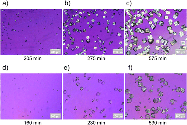
To investigate the mechanism behind interpenetration within this system, biphenyl-4,4′-dicarboxylic acid was reacted with zinc in the absence and the presence of additive while optically monitoring the crystallization to observe the formation of birefringent and non-birefringent phases during synthesis (see ESI† for experimental details). Images were captured under cross polarizers with a half wave plate throughout each synthesis, and timelapses‡ of crystallizations with and without additive were created (see ESI† for full video). Fig. 2 includes images captured during the stages of crystallization with corresponding timepoints for MOFs synthesized both in the absence (Fig. 2a–c) and presence (Fig. 2d–f) of additive. These earliest crystallization appearances, corresponding to shortly after nucleation, observed from in situ imaging, provided further insight into the mechanism behind interpenetration within this system. Specifically, the additive facially blocks crystal growth within the initially formed non-interpenetrating framework, thereby suppressing interpenetration, and favoring the formation of crystallographically cubic IRMOF-10 crystals with rhombic dodecahedral morphologies (Fig. 2d). As the synthesis progresses, a second framework, as evidenced by new birefringent regions, nucleates within initially formed IRMOF-10 (Fig. 2e), resulting in the formation of mixed phase IRMOF-9/10 crystals (Fig. 2f). IRMOF-10 forms during the initial stages of synthesis as a result of the kinetic influence of the additive, and the lack of interpenetration suppression at later times indicates that ultimately the thermodynamic product (IRMOF-9) prevails under these conditions. These results contrast with the nucleation of IRMOF-9 (in the absence of additive, Fig. 2a–c) where the thermodynamic product is observed to a much greater extent earlier in the synthesis.
 | ||
| Fig. 2 Images of IRMOF-9 crystals at 205 min (a), 275 min (b), and 575 min (c) into synthesis. Images of IRMOF-9/10 crystals at 160 min (d), 230 min (e), and 530 min (f) into synthesis. | ||
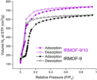
Previous attempts to activate IRMOF-9 by traditional evacuation methods has resulted in gravimetric surface areas ranging from 1168–1904 m2 g−1.15,23 In this study, DMF solvated IRMOF-9 and IRMOF-9/10 crystals were activated with flowing supercritical CO2 and analyzed by N2 gas sorption (Fig. 3, see ESI† for details).24 Near type I isotherm behavior was observed for both samples, with IRMOF-9 exhibiting its characteristic stepwise isotherm12,15 and a BET surface area of 1964 m2 g−1. This stepwise behavior has been attributed to pore expansion (or ‘gating’) during N2 adsorption,12 with another study demonstrating such flexibility within IRMOF-9 via solvent coordination-induced breathing.25 It is noteworthy that the mixed phase IRMOF-9/10 material exhibits the stepwise behavior to a lesser extent during adsorption, and has a significantly higher BET surface area (2369 m2 g−1) than IRMOF-9. It is likely that the instability of the IRMOF-10 framework upon activation renders the theoretical surface area of 5000 m2 g−1 unachievable by current activation methods. Nonetheless, this improvement in surface area demonstrates the efficacy of structurally-informed additive design to suppress interpenetration and yield higher surface area MOFs. However, further reducing the extent of interpenetration, by stopping crystallizations at the initial onset of birefringence (2–6 hours total synthesis time), resulted in lower BET surface areas ranging from 1200–1400 m2 g−1 (see ESI† for details and characterization). Therefore, partial interpenetration is hypothesized to have a stabilizing effect on regions with reduced interpenetration.
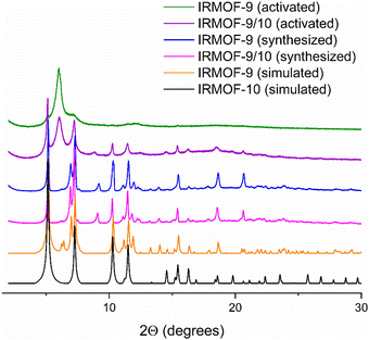
In alignment with previous studies,12,15,23 we observed amorphization of IRMOF-9 post-activation via PXRD. In contrast to IRMOF-9, the PXRD patterns of IRMOF-9/10 samples showed a greater retention of crystallinity post-activation, with the sample retaining characteristic signals of IRMOF-10 (5.0°, 7.3°, 10.3°, and 11.5° 2θ) and aligning with the simulated pattern of IRMOF-10 (Fig. 4). Furthermore, these data demonstrate that no alternative phases formed due to the presence of additive during the synthesis of IRMOF-9/10, and furthermore additive is detectable at levels <1 mol% via 1H NMR analysis of IRMOF-9/10 digested in DCl/D2O/DMSO-d6 (see ESI†) consistent with a transient role of the additive in both morphology control and interpenetration suppression.
In summary, a geometric design strategy was exploited to experimentally suppress interpenetration of IRMOF-10 via inclusion of a lattice interacting additive. This yields a material with a gravimetric surface area surpassing those reported for IRMOF-9 and IRMOF-10 to date. The resulting crystals, synthesized under traditional solvothermal conditions, were of sufficient size and quality to determine the single crystal structure of IRMOF-10 for the first time. In addition, in situ optical monitoring during the crystallization of IRMOF-9/10 suggests a mechanism of interpenetration involving formation of IRMOF-10 followed by subsequent nucleation of IRMOF-9 within the initially formed crystals and the additive dramatically slowing down nucleation and growth of the interpenetrating framework. This additive approach can be broadly applied to suppress interpenetration and achieve higher surface areas across a variety of MOFs.
This work was funded by the U.S. Department of Energy, Office of Science, Basic Energy Sciences-grant no. DE-SC0004888. C. A. C. acknowledges the Rackham Predoctoral Fellowship Program for financial support. The authors acknowledge George Hernandez for his assistance in helping prepare MOF solutions for timelapse collection.
Data availability
The data supporting this article have been included as part of the ESI† including: Experimental procedures, characterization, and crystallographic data. Crystallographic data for [IRMOF-10] has been deposited at the [CCDC] under [2356184].† For ESI,† crystallographic data in CIF format, and video see https://doi.org/10.1039/d4cc03138e.Conflicts of interest
There are no conflicts to declare.Notes and references
- (a) M. Eddaoudi, J. Kim, N. Rosi, D. Vodak, J. Wachter, M. O’Keeffe and O. M. Yaghi, Science, 2002, 295, 469–472 CrossRef CAS PubMed; (b) U. Mueller, M. Schubert, F. Teich, H. Puetter, K. Schierle-Arndt and J. Pastré, J. Mater. Chem., 2006, 16, 626–636 RSC.
- J. L. C. Rowsell, A. R. Millward, K. S. Park and O. M. Yaghi, J. Am. Chem. Soc., 2004, 126, 5666–5667 CrossRef CAS PubMed.
- B. Panella, K. Hönes, U. Müller, N. Trukhan, M. Schubert, H. Pütter and M. Hirscher, Angew. Chem. Int. Ed., 2008, 47, 2138–2142 CrossRef CAS PubMed.
- D. Y. Siberio-Pérez, A. G. Wong-Foy, O. M. Yaghi and A. J. Matzger, Chem. Mater., 2007, 19, 3681–3685 CrossRef.
- J. I. Feldblyum, A. G. Wong-Foy and A. J. Matzger, Chem. Commun., 2012, 48, 9828–9830 RSC.
- N. L. Rosi, M. Eddaoudi, J. Kim, M. O’Keeffe and O. M. Yaghi, CrystEngComm, 2002, 4, 401–404 RSC.
- T. A. Makal, A. A. Yakovenko and H.-C. Zhou, J. Phys. Chem. Lett., 2011, 2, 1682–1689 CrossRef CAS.
- M. Gupta and J. J. Vittal, Coord. Chem. Rev., 2021, 435, 213789 CrossRef CAS.
- J. L. C. Rowsell and O. M. Yaghi, Angew. Chem., Int. Ed., 2005, 44, 4670–4679 CrossRef CAS PubMed.
- H.-L. Jiang, T. A. Makal and H.-C. Zhou, Coord. Chem. Rev., 2013, 257, 2232–2249 CrossRef CAS.
- J. Zhang, L. Wojtas, R. W. Larsen, M. Eddaoudi and M. J. Zaworotko, J. Am. Chem. Soc., 2009, 131, 17040–17041 CrossRef CAS PubMed.
- R. Babarao, C. J. Coghlan, D. Rankine, W. M. Bloch, G. K. Gransbury, H. Sato, S. Kitagawa, C. J. Sumby, M. R. Hill and C. J. Doonan, Chem. Commun., 2014, 50, 3238–3241 RSC.
- T.-H. Park, K. Koh, A. G. Wong-Foy and A. J. Matzger, Cryst. Growth Des., 2011, 11, 2059–2063 CrossRef CAS.
- O. K. Farha, K. L. Mulfort, A. M. Thorsness and J. T. Hupp, J. Am. Chem. Soc., 2008, 130, 8598–8599 CrossRef CAS PubMed.
- A. B. Crom, J. L. Strozier, C. J. Tatebe, C. A. Carey, J. I. Feldblyum and D. T. Genna, Chem. – Eur. J., 2023, 29, e202302856 CrossRef CAS PubMed.
- J. K. Schnobrich, K. Koh, K. N. Sura and A. J. Matzger, Langmuir, 2010, 26, 5808–5814 CrossRef CAS PubMed.
- K. S. Walton and R. Q. Snurr, J. Am. Chem. Soc., 2007, 129, 8552–8556 CrossRef CAS PubMed.
- T. Düren, F. Millange, G. Férey, K. S. Walton and R. Q. Snurr, J. Phys. Chem. C, 2007, 111, 15350–15356 CrossRef.
- A. Ahmed, S. Seth, J. Purewal, A. G. Wong-Foy, M. Veenstra, A. J. Matzger and D. J. Siegel, Nat. Commun., 2019, 10, 1568 CrossRef PubMed.
- J. Borycz, D. Tiana, E. Haldoupis, J. C. Sung, O. K. Farha, J. I. Siepmann and L. Gagliardi, J. Phys. Chem. C, 2016, 120, 12819–12830 CrossRef CAS.
- K. Suresh, A. P. Kalenak, A. Sotuyo and A. J. Matzger, Chem. – Eur. J., 2022, 28, e202200334 CrossRef CAS PubMed.
- K. Suresh, D. Aulakh, J. Purewal, D. J. Siegel, M. Veenstra and A. J. Matzger, J. Am. Chem. Soc., 2021, 143, 10727–10734 CrossRef CAS PubMed.
- J. L. C. Rowsell and O. M. Yaghi, J. Am. Chem. Soc., 2006, 128, 1304–1315 CrossRef CAS PubMed.
- B. Liu, A. G. Wong-Foy and A. J. Matzger, Chem. Commun., 2013, 49, 1419–1421 RSC.
- S. Canossa, P. Pelagatti and A. Bacchi, Isr. J. Chem., 2018, 58, 1131–1137 CrossRef CAS.
Footnotes |
| † Electronic supplementary information (ESI) available: Experimental procedures, characterization, and crystallographic data. CCDC 2356184. For ESI and crystallographic data in CIF or other electronic format see DOI: https://doi.org/10.1039/d4cc03138e |
| ‡ A playback speed of 3 frames per second was used to create the timelapse video. |
| This journal is © The Royal Society of Chemistry 2024 |


