DOI:
10.1039/D1RA01218E
(Paper)
RSC Adv., 2021,
11, 13229-13244
Efficient non-metal based conducting polymers for photocatalytic hydrogen production: comparative study between polyaniline, polypyrrole and PEDOT†
Received
14th February 2021
, Accepted 31st March 2021
First published on 8th April 2021
Abstract
Incorporation of conducting polymers (CPs) with TiO2 is considered a promising pathway toward the fabrication of highly efficient non-metal based photocatalysts. Herein, we report the fabrication of TiO2@polyaniline, TiO2@polypyrrole, and TiO2@poly(3,4-ethylenedioxythiophene) photocatalyst heterostructures via the facile wet incipient impregnation method. The mass ratios of CPs in the composites were optimized. The structure, morphology, optical and surface texture of the samples were characterized by XRD, TEM, TGA, DRS, and N2-physisorption techniques. The TiO2@2PEDOT, TiO2@2PPy, and TiO2@5PAn composites were found to exhibit the highest H2 evolution rate (HER) of 1.37, 2.09, and 3.1 mmol h−1 g−1, respectively. Compared to bare TiO2, the HER was significantly enhanced by 16, 24, and 36-fold, respectively. Photoelectrochemical measurements (CV, CA and EIS) were conducted, to evaluate the photoelectric properties of the synthesized composites and assist in understanding the photocatalytic mechanism. The deposition method plays a key-role in forming the photocatalyst/CP interface. This simple impregnation route was found to provide an excellent interface for charge transfer between composite components compared to chemisorption and in situ polymerization methods. This study sheds light on the promising effect of CP incorporation with semiconductor photocatalysts, as a cheap and efficient matrix, on photocatalytic performance.
1. Introduction
Increasing dependence on fossil fuel, as a main source of energy, produces very harmful emissions that cause environmental problems. In addition, the amount of fossil fuels is limited, and will run out one day.1,2 Therefore, it is urgent to develop new sustainable, eco-friendly, and cheap sources of energy. Photocatalytic hydrogen generation via water splitting is an efficient strategy to substitute fossil fuel.3 This can be achieved by means of solar energy using suitable semiconductor photocatalysts.
In 1972, Fujishima and Honda successfully achieved water splitting over a TiO2 photoelectrode via photoelectrolysis.4 Since this moment, photocatalysis has been revealed to be one of the most promising approaches to the sustainable production of hydrogen as a fuel from water.5,6 Several semiconductor materials, such as TiO2, ZnO, Ta2O5, CdS, and g-C3N4, have been extensively investigated for photocatalytic hydrogen production from water.7–9 Until this day, TiO2 attracted a broad attention as a photocatalyst due to its availability, chemical stability, non-corrosive and catalytic activity.10,11,72 However, the wide optical band gap of TiO2 (3.2 eV) restricts its ability to harness visible light. Furthermore, it suffers from a high recombination rate of photogenerated charge carriers and low catalytic active sites with low overpotential. These drawbacks limit the overall photocatalytic efficiency of TiO2. In order to overcome these limitations, several methods were employed to improve the photocatalytic activity and visible light harvesting capacity of TiO2. For example, loading of noble and non-noble metals,12,13,73 incorporation of graphene nanosheets,14,15 and dye sensitization.16,17 Nevertheless, loading of noble and transition metals makes remarkable enhancement in activity, still they suffer from non-favorable band gap position, high cost, and possible environmental risks. Moreover, most dye sensitizers used suffer from low stability during light excitation or high toxicity.18,19 Therefore, it's a crucial topic to design material which possesses the fundamental requirements of chemical stability, visible light absorptivity, and low cost.
Since the pioneering discovery of conducting polyacetylene doped iodine by Alan J. Heeger, Alan MacDiarmid and Hideki Shirakawa in 1977,20 many researches have been investigating the intrinsic properties of conducting polymers (CPs). It was found that conducting polymers possess superior properties due to the intrinsic continuous π-conjugation.21 For instance, excellent electrical conductivity, controllable optical properties, chemical stability and high surface area.22 Consequently, CPs have been a potential candidate in many fields such as batteries,23 supercapacitors,24 solar cells,25 solar energy26–29 and many others applications.30,31 Various polymeric materials such as polyaniline, polypyrrole, polythiophene, and their derivatives, have been incorporated with semiconductor photocatalysts as good hole conductors with high visible light absorptivity.32,33 It is worthy to mention that non-metal based-PAn exhibited significant effective separation of photogenerated electron–hole pairs.34 Moreover, the deposition of TiO2 into PPy matrix showed better photocatalytic activity.35,36 However, most reported studies regarding the modification of TiO2 with CPs lack information about the synergistic effect of the heterojunction and the detailed band gap structure validation in addition to the enhancement mechanism. Furthermore, up to our best knowledge, no study has focused on the effect of the deposition methods on the architecture between TiO2 and CPs and the influence of counterion doped CPs on photocatalytic performances. As the deposition method has an effective role in forming an intimate contact at the surface between CPs and TiO2, resulting in better separation and migration of charge carriers. Therefore, our study will introduce a complete vision on modifying the TiO2 with different categories of CPs for effective hydrogen production via water-splitting.
Herein, photocatalytic hydrogen generation from water have been comparatively investigated using TiO2 decorated with various CPs (polyaniline, polypyrrole and poly(3,4-ethylenedioxythiophene)). At first, we have synthesized the CPs via conventional chemical polymerization route using ammonium persulfate as oxidant and chloride counter ion as dopant for enhancing conductivity. Afterwards, different series of TiO2@CPs composites with different weight ratios were synthesized, for first time, through incipient wet impregnation deposition technique which is simple, low cost, and reproducible. To the best of our knowledge, the current study is the first to compare the photocatalytic activities of TiO2 based-CPs (TiO2@PAn, TiO2@PPy, and TiO2@PEDOT) for hydrogen production from methanol–water mixture under UV irradiation. The plausible suggested mechanism of photocatalytic hydrogen production over synthesized composites is also investigated to illustrate the synergism at contact interfaces.
2. Materials and methods
2.1. Chemicals
TiO2 (P25, Degussa), hydrochloric acid (37%), dimethylformamide (DMF), aniline monomer (99%), ammonium peroxydisulfate (APS), isopropanol, and methanol were obtained from Fisher Scientific. Pyrrole monomer (98%) and poly(3,4-ethylenedioxythiophene)–poly(styrenesulfonate) 1.3 wt% dispersion in H2O, conductive grade were purchased from Sigma-Aldrich. All chemicals reagents were analytical pure and used without further purification.
2.2. Synthesis of polyaniline (PAn) and polypyrrole (PPy)
The conventional chemical oxidative polymerization method is utilized to prepare polyaniline (PAn) and polypyrrole (PPy) composite materials in an aqueous solution of HCl and APS oxidant as described in the IUPAC technical report with some minor modifications.37 Typically, 50 mL of 1 M HCl solution containing 2 mL of aniline or pyrrole monomer were stirred for 30 minutes in an ice bath (0–5 °C), then 50 mL of pre-cooled 1 M HCl containing a certain amount of APS (monomer/oxidizing reagent mol ratio (1![[thin space (1/6-em)]](https://www.rsc.org/images/entities/char_2009.gif) :
:![[thin space (1/6-em)]](https://www.rsc.org/images/entities/char_2009.gif) 2) were used) were added dropwise under continuous stirring from burette for about 1 h. Subsequently, the polymerization was performed by stirring the reactants solution in the ice bath for more 6 h. Afterwards, the obtained precipitates were vacuum filtered, and washed several times with 1 M HCl, distilled water and methanol till discoloration of the filtrate, then dried for 24 h at 60 °C till constant mass. The dried PPy and PAn was fine grounded using agate mortar and then used. The systematic illustration of stepwise preparation of PAn and PPy described in Fig. S1.† Similarly, the polyaniline doped with different counter ions, NO3− and SO42−, were prepared by the same abovementioned procedure but HCl was replaced with HNO3 and H2SO4, respectively.
2) were used) were added dropwise under continuous stirring from burette for about 1 h. Subsequently, the polymerization was performed by stirring the reactants solution in the ice bath for more 6 h. Afterwards, the obtained precipitates were vacuum filtered, and washed several times with 1 M HCl, distilled water and methanol till discoloration of the filtrate, then dried for 24 h at 60 °C till constant mass. The dried PPy and PAn was fine grounded using agate mortar and then used. The systematic illustration of stepwise preparation of PAn and PPy described in Fig. S1.† Similarly, the polyaniline doped with different counter ions, NO3− and SO42−, were prepared by the same abovementioned procedure but HCl was replaced with HNO3 and H2SO4, respectively.
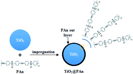 |
| | Fig. 1 Schematic illustration of TiO2@PAn composite fabrication. | |
2.3. Synthesis of photocatalyst nanocomposites
Series TiO2@PAn, TiO2@PPy, and TiO2@PEDOT nanocomposites with different mass ratios were synthesized via the wet incipient impregnation route as shown in (Fig. 1). In typical procedure, one gram of TiO2 powder was put into a porcelain crucible and the desired amount of PAn or PPy precursor was dissolved in the least amount of DMF solution, then mixed together by ultra-sonication to form a homogenous suspension. After that, the whole mixture was heated over a water bath with stirring by glass rod till total dryness. Next, the recovered solid was collected and dried overnight at 60 °C. The TiO2@PEDOT nanocomposites were prepared with the same procedure mentioned above except the calculated volume of PEDOT/PSS solution dispersed in 4 mL of 1 M HCl with magnetic stirring. The PEDOT/PSS exhibits relatively low electrical conductivity; hence the acid treatment enhances the conductivity as reported elsewhere.38 The prepared composites were labeled as TiO2@xPAn, TiO2@xPPy, and TiO2@xPEDOT where x refers to the weight percent of the corresponding polymer relative to TiO2. For comparison purposes, the TiO2@PAn composite were fabricated by conventional chemisorption and in situ polymerization methods as describe in the literature which are donated as TiO2@PAn_Ads and TiO2@PAn_Insitu, respectively.33,39
2.4. Characterization
The as-prepared photocatalyst composites were characterized using various techniques. The crystal structures and phases of the samples were recorded on a Philips 1700 version diffractometer equipped with Cu Kα radiation (40 kV, 30 mA). The particle size and morphologies were examined by transmission electron microscope JSM-2100 (JEOL, Japan) using accelerating voltage 200 kV and scanning electron microscope (SEM, JSM-6360LA, JOEL, Japan). The UV-Visible diffuse reflectance spectroscopy (DRS) of powder composites were acquired from 1100–200 nm using Evolution 220 spectrophotometer coupled with ISA-220 integrating sphere (Thermo Fisher Scientific, UK). Thermogravimetric analysis (TGA) was recorded up to 500 °C using the TA 60 thermal analyzer apparatus (Shimadzu, Japan) with a heating rate and nitrogen rate of 10 °C min−1, and 40 mL min−1, respectively The specific surface areas were determined by N2 adsorption–desorption isotherm (Quantachrome Instrument Corporation, Nova 3200, USA) using Brunauer–Emmett–Teller (BET) calculations, whereas the pore size distributions were recorded by desorption branch using BJH method. The photoluminescence spectra of the prepared nanocomposites were acquired using fluorescence spectrophotometer (Cary Eclipse, Agilent USA). The FTIR spectra were conducted using NICOLET IS 10 (ThermoScientific, USA) in the wavenumber range of 400–4000 cm−1.
2.5. Photocatalytic hydrogen evolution
The photocatalytic activity of synthesized samples was tested in a continuous flow system equipped with 200 mL flat side irradiation window Pyrex cell at ambient temperature. In typical procedure, 50 mg of the as-prepared sample was dispersed by ultra-sonication in a 200 mL of 20% (v/v) aqueous methanol solution as a hole scavenger without pH adjustment. The mixed solution was purged with argon gas (99.99%) to remove dissolved air (100 mL min−1 for 30 min) under continuous magnetic stirring (800 rpm) to prevent sedimentation of particles. Then irradiated with UV-LED (25 W, 365 nm, NVMUR020A, NICHIA, Japan) as light source. The distance between the reaction cell and the light source was kept constant at 1 cm. The typical photocatalytic experiment proceeds for 5 h at room temperature. The amount of evolved hydrogen gas was determined every 15 min by gas chromatography (Shimadzu, GC-2014) equipped with a thermal conductivity detector and Shin Carbon packed column (ST 80/100 2 m, 2 mm ID), as shown in Fig. 2.
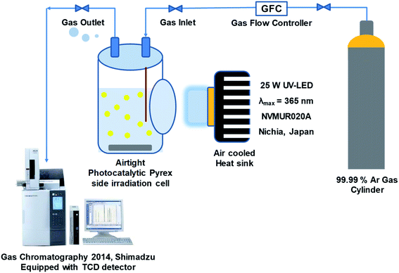 |
| | Fig. 2 Photocatalytic hydrogen production flow system. | |
2.6. Photoelectrochemical measurements
Electrochemical measurements namely chronoamperometry (CA), electrochemical impedance spectroscopy (EIS), and cyclic voltammetry (CV) were conducted to evaluate the photocatalytic performance of the as prepared nanocomposites and assist understanding the photocatalytic mechanism. First, fluorine-doped tin oxide (FTO) substrates, were used as working electrodes, were cleaned by deionized water and isopropanol repeatedly in ultrasonic bath. The TiO2, TiO2@2PEDOT, TiO2@2PPy, and TiO2@5PAn photoelectrodes were prepared by wet chemical deposition technique. Briefly, 20 mg of the obtained composites were dispersed in 1 mL of isopropanol solution by ultra-sonication for 15 min to obtain viscous slurry. 200 μL of well suspended slurry of the sample (4 layers, 50 μL each) were uniformly spread onto a pre-cleaned FTO glass (1 cm × 1.5 cm), then dried at 80 °C for 1 h.
A three-electrode square quartz cell (50 mL capacity) was employed for the photoelectrochemical measurements of the prepared photoelectrodes at room temperature. In which, a platinum wire serves as a counter electrode, a saturated Ag/AgCl electrode was used as the reference electrode and the powder sample deposited over FTO acts as a working electrode. The electrodes were immersed in 0.1 M Na2SO4 electrolyte solution, then connected to potentiostat workstation (CorrTest Instruments, model CS350). Before measurement, the electrolyte was purged with argon gas to remove dissolved air, and UV-LED (25 W, 365 nm, NVMUR020A, NICHIA, Japan) was employed as the light source through the measurements. Cyclic voltammetry (CV) was measured in a potential range from 1 to −1 V (versus sat. Ag/AgCl) with scan rate of 50 mV s−1. Electrochemical impedance spectroscopy (EIS) measurement was carried out at 20 mV signal of amplitude over covering frequency range from 105 to 0.01 Hz under light irradiation. The transient photocurrent responses were also measured using chronoamperometry (CA) at fixed potential of 0.6 V for 660 s.
3. Results and discussion
3.1. FTIR spectra
In order to ensure the success of the fabrication of CPs and TiO2 heterojunction, FTIR spectra of the prepared conducting polymers, bare- TiO2, TiO2@PEDOT, TiO2@PPy, and TiO2@PAn have been performed as shown in Fig. 3. The characteristic absorption bands of polyaniline appear at 1130, 1561, and 1480 cm−1 are assigned to quinonoid ring in doped-PAn, C–C stretching of quinonoid units and C–C, C![[double bond, length as m-dash]](https://www.rsc.org/images/entities/char_e001.gif) C stretching modes in a benzenoid unit, respectively. Moreover, benzene structure of C–N stretching vibration peak at 1293 cm−1, quinonoid structure of C–N stretching vibration peak at 1240 cm−1.40 While, in the case of PPy, the absorption bands at 1188 and 1555 cm−1 could be attributed to N–C stretching, and the ring stretching mode of pyrrole.41 To further confirm the existence of CPs in the as-prepared samples, the FTIR spectra of bare and modified TiO2 were conducted as presented in Fig. 3b. The broad band appears at 3500 cm−1 is indexed to ν(OH) of physically adsorbed water molecules on the composite surface. Also, the band at 1650 cm−1 in the spectrum of bare-TiO2 could be indexed to O–H stretching vibration, indicating the presence of hydrogen-bonding. For TiO2@PAn nanocomposites, multiple absorption bands were obtained at 1130, 1500, and 1590 cm−1, proving the incorporation of PAn backbone. The observed shift toward higher wavenumbers, indicating the significant interactions between TiO2 and polymers chains which is favorable for the electron transfer process.42 In the same way, for TiO2@PPy, the characteristic band of the PPy ring appeared at 1480, 1550, and 1178 cm−1. Also, the bands at 1180 and 1620 cm−1 in the spectrum of TiO2@PEDOT are attributed to C–C and C
C stretching modes in a benzenoid unit, respectively. Moreover, benzene structure of C–N stretching vibration peak at 1293 cm−1, quinonoid structure of C–N stretching vibration peak at 1240 cm−1.40 While, in the case of PPy, the absorption bands at 1188 and 1555 cm−1 could be attributed to N–C stretching, and the ring stretching mode of pyrrole.41 To further confirm the existence of CPs in the as-prepared samples, the FTIR spectra of bare and modified TiO2 were conducted as presented in Fig. 3b. The broad band appears at 3500 cm−1 is indexed to ν(OH) of physically adsorbed water molecules on the composite surface. Also, the band at 1650 cm−1 in the spectrum of bare-TiO2 could be indexed to O–H stretching vibration, indicating the presence of hydrogen-bonding. For TiO2@PAn nanocomposites, multiple absorption bands were obtained at 1130, 1500, and 1590 cm−1, proving the incorporation of PAn backbone. The observed shift toward higher wavenumbers, indicating the significant interactions between TiO2 and polymers chains which is favorable for the electron transfer process.42 In the same way, for TiO2@PPy, the characteristic band of the PPy ring appeared at 1480, 1550, and 1178 cm−1. Also, the bands at 1180 and 1620 cm−1 in the spectrum of TiO2@PEDOT are attributed to C–C and C![[double bond, length as m-dash]](https://www.rsc.org/images/entities/char_e001.gif) C bonds of the thiophene ring.43 Low intensities of CPs absorption bands due to their relatively low contents in the as-prepared composites. However, we could conclude the successful incorporation of CPs in the as-fabricated samples.
C bonds of the thiophene ring.43 Low intensities of CPs absorption bands due to their relatively low contents in the as-prepared composites. However, we could conclude the successful incorporation of CPs in the as-fabricated samples.
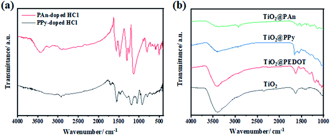 |
| | Fig. 3 FTIR spectra of (a) PAn-doped HCl and PPy-doped HCl, and of (b) bare-TiO2, TiO2@PEDOT, TiO2@PPy, and TiO2@PAn composites. | |
3.2. X-ray diffraction (XRD)
The XRD patterns of the as-prepared composites are presented in Fig. 4. As shown, the samples exhibit the main diffraction peaks assigned to planes of anatase TiO2 (JCPDS No. 71-1167) at 25.3°, 37.8° and 48.0° and weak peaks at 27.5°, 36.1° and 41.3° attributed to planes of rutile TiO2 (JCPDS No. 77-0442). No obvious diffraction peaks appeared for modified composites, may be owing to small contents of CPs which under XRD visibility. Moreover, CPs have low crystallinity as shown in Fig. S3,† therefore they don't significantly influence the crystal phases of TiO2.
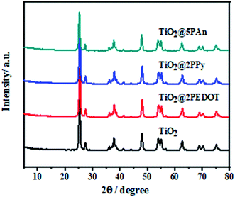 |
| | Fig. 4 X-ray diffraction patterns of TiO2, TiO2@2PEDOT, TiO2@2PPy, and TiO2@5PAn. | |
3.3. Transmission and scanning electron microscope (TEM) analysis
Morphological structure of pure PAn and TiO2@PAn composited were investigated via SEM as presented in Fig. S4.† As shown, polyaniline polymer chains have irregular micromorphology which consisted of larger aggregates with rough surface. The coating of TiO2 with PAn layer has no significant effect on the morphological structure of TiO2 nanoparticles due to its low content in the composite. In order to investigate the morphological structure and particles size distribution of the obtained samples, low magnification TEM analysis was carried out. As illustrated in Fig. S5(a),† we could clearly observe that TiO2 nanoparticles had irregular spherical structure with a particle size lies in the range from 10 to 25 nm. As seen in Fig. S5(b–d),† the morphology and particle diameter have not been affected via modification with conducting polymers. Also, the pure and modified TiO2 nanoparticles appear aggregated due to high surface energy of particles. High magnification TEM images of the as-fabricated samples of TiO2@2PEDOT, TiO2@2PPy, and TiO2@5PAn, are shown in Fig. 5. From the obtained images, we confirmed the presence of crystallized TiO2 nanostructured encompassed with very thin layer of amorphous CPs as it represents very low content of the composites. Same observations of CPs dispersed as a single layer on the surface of the semiconductor were reported elsewhere.44,45 Although the relative low content of CPs in the as-prepared composites, a thin layer of CPs coated the edges of TiO2 could be observed. The CPs amorphous layer revealed by HR-TEM are homogeneously deposited on the TiO2 surface, with thickness approximately of 0.71, 0.45 and 0.33 nm for PAn, PPy and PEDOT, respectively, similar results was reported by Zhang et al.,46,47 because they may be forming a very thin film of conductive layer with small thickness like core shell structure as reported Though the powder color was completely changed after CPs incorporation as seen in Fig. S6.† To further confirm the distribution of CPs in the prepared composites, TEM-EDX elemental mapping were performed. The presence of all elements (Ti, O, C, N, and S) that correspond to each composite were clearly proved as shown in Fig. S7–S9.† From TEM-EDX analysis and photophysical properties, it could be concluded that CPs were deposited evenly on the host photocatalyst which is regarded as an indication of a successful deposition method.
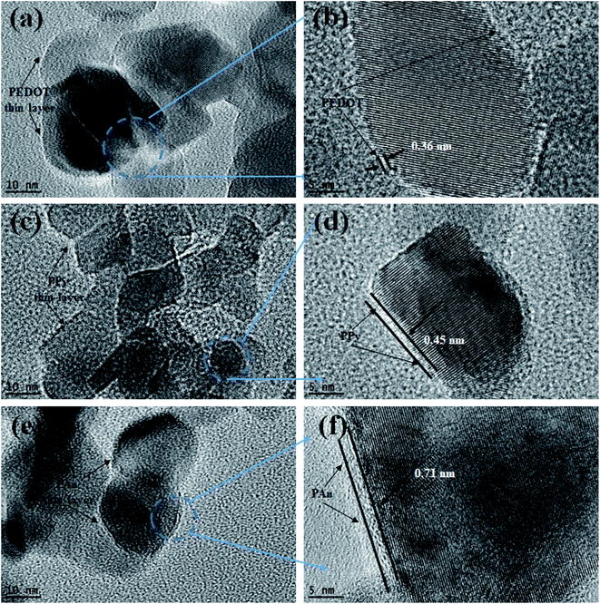 |
| | Fig. 5 HRTEM images of (a, b) TiO2@2PEDOT, (c, d) TiO2@2PPy, and (e, f) TiO2@5PAn composites. | |
3.4. UV-visible diffuse reflectance spectroscopy (DRS)
UV-Vis diffuse reflectance spectra of the as-modified samples are shown in Fig. 6. It is clearly observed that the pure TiO2 absorbs below 400 nm. However, when it's incorporated with a small amount of any of the investigated CPs (PEDOT, PPy, or PAn) an extension of photoresponse of bare TiO2 to visible region takes place. This could be attributed to CPs acting as efficient photosensitizer materials for catching large amount of visible light photons which confirmed by the color change of as-prepared samples (inset Fig. 5).48,49 The optical band gap was calculated using transformed Kubelka–Munk function50 as illustrated in Fig. 6(b), and the band gaps values are listed in Table 1. This confirms the effect of CPs as an efficient visible light harvesting photosensitizer.51
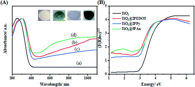 |
| | Fig. 6 (A) UV-Vis diffuse reflectance spectra of (a) TiO2, (b) TiO2@2PEDOT, (c) TiO2@2PPy, and (d) TiO2@5PAn, (B) plots of transformed KM function. | |
Table 1 Surface texture and optical band gap
| Photocatalyst |
Optical band gap (eV) |
BET surface area (m2 g−1) |
Mean pore radius (nm) |
Total pore volume (cm3 g−1) |
| TiO2 |
3.00 |
124.7 |
1.77 |
0.268 |
| TiO2@2PEDOT |
2.70 |
11.7 |
11.68 |
0.120 |
| TiO2@2PPy |
2.75 |
13.7 |
12.06 |
0.139 |
| TiO2@5PAn |
2.74 |
10.4 |
11.55 |
0.105 |
3.5. BET surface areas and pore distributions
To determine the changes in the specific surface area and the corresponding pore size distribution of the as-prepared photocatalysts, the N2 adsorption–desorption isotherms were carried out at 77 k as presented at Fig. 7. The obtained adsorption–desorption isotherm curves of all samples were identified to be of type III. The surface texture parameters i.e. BET surface area, mean pore radius, and total pore volume are grouped in Table 1. It was found that the BET specific surface area has decreased for all modified composites compared to TiO2. The values of specific surface areas are 11.683, 13.729, and 10.6431 m2 g−1 for TiO2@2PEDOT, TiO2@2PPy and TiO2@5PAn, respectively. Likewise, the pore volume follows the same trend due to an out layer of polymer chains formed around the surface perimeter of TiO2 particles. Also, TiO2 has a narrow pore size distribution with pore radius of about 1–6 nm, whereas the modified composites showed more broad pore size distribution around 20–60 nm. This may also suggest that CPs were loaded on the TiO2 surface and formed a core shell structure.52 Unlike the photocatalytic activity, the incorporation of CPs with TiO2 nanoparticles have noticeably reduced the specific surface area of the as-prepared composites, similar results have been reported previously.53 This could be attributed to the CPs may either get distributed onto the host photocatalyst surface or may go inside and occupy the pores or both. Consequently, the TiO2 pores is blocked and the BET surface area is reduced. This was clearly confirmed by the obvious drop in the pore volume values after decoration with CPs. Also, it is deemed as evidence for forming the core–shell structure which is consistent with the obtained results from HR-TEM.
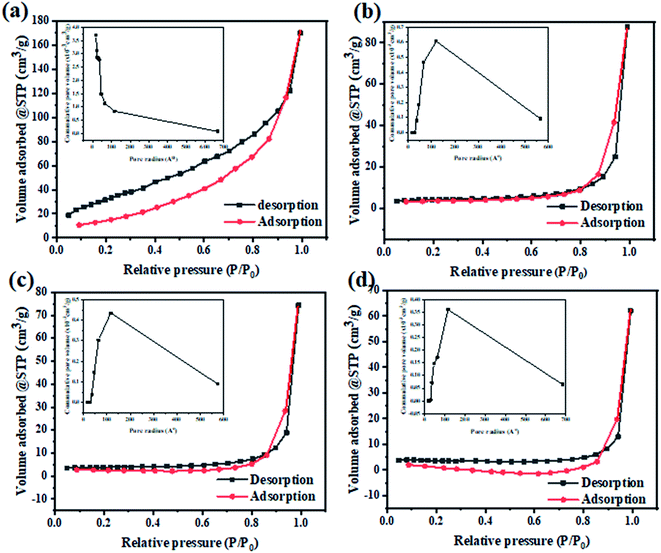 |
| | Fig. 7 The N2 adsorption–desorption isotherm and particles pore distribution of (a) TiO2, (b) TiO2@2PEDOT, (c) TiO2@2PPy, and (d) TiO2@5PAn nanocomposites. | |
3.6. Thermal stability
To evaluate the thermal stability of the as-synthesized samples, the thermogravimetric analysis (TGA) have been investigated in nitrogen atmosphere. Fig. 8 depicts the representation of TGA curves from ambient temperature to 500 °C with heating rate of 10 °C min−1 for all samples. As displayed in these curves, two main losses are presented. The first loss starts at 120 °C and ends approximately at 330 °C which is mainly caused to by removal of chemically adsorbed water molecules and some oligomers. The other from 330 to 480 °C is ascribed to decomposition of polymer chains. Therefore, all the modified composites exhibit excellent thermal stability; the thermolysis of polymers happens at elevated temperatures with a gradual weight loss. According to mass loss, the doping content of PEDOT, PPy, and PAn is found to be 1.3%, 1.6%, and 2.9%, where the actual addition amount is 2%, 2%, 5% respectively. The experimental dosage of polymers isn't in agreement with theoretical amount, which might be due to formed residual carbon materials. The continuous loss of polymers over a wide temperature range is due to high degree of polymer cross-linking, extended π-conjugated double bonds, and strong interaction between CPs and TiO2. As a consequence of the mentioned factors, the dissociation bond energy is increased and hence the thermal stability is improved.
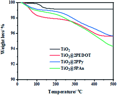 |
| | Fig. 8 TGA curves of TiO2@2PEDOT, TiO2@2PPy, and TiO2@5PAn nanocomposites. | |
3.7. Photocatalytic hydrogen generation
The photocatalytic hydrogen generation activities of bare-TiO2, CPs, and TiO2@CPs heterojunction composites with different mass ratio were evaluated under ultraviolet light irradiation (λ = 365 nm) in a water–methanol solution. The incorporation pathway of CPs matrix with TiO2 is expected to play an important role in forming the CP/photocatalyst interface and the charge transfer between the composite components. Therefore, first, we have evaluated different CPs deposition methods in order to assess their effect on the photocatalytic hydrogen generation. For that, three methods were put to test, namely, chemisorption, in situ polymerization and incipient wet impregnation methods, to prepare TiO2@5PAn nanocomposite as presented in Fig. 9. We have found that the simple impregnation method was the best, from both the activity and stability of the composite. The initial and cumulative (5 h) HER was 2.19, 2.10, 3.10 mmol g−1 h−1 and 10.3, 8.72, and 15.15 mmol g−1 for TiO2@5PAn prepared by adsorption, in situ polymerization and incipient wet impregnation methods, respectively. The impregnation method has proven to possess many merits compared to other methods, for instance, simplicity, efficiency, low cost and reproducibility. Additionally, the influence of various counterions, which doped-PAn, on H2 amount were further studied and the obtained results are shown in Fig. 9b. We found that the HCl-doped PAn exhibited the highest photocatalytic activity compared to HNO3-doped PAn and H2SO4-doped PAn which maybe related to the electrical conductivity. The post-treatment of PEDOT/PSS with acids is considered an efficient pathway to enhance the conductivity, as previously reported.54 Thus, we have post-treated PEDOT/PSS with HCl to enlarge its conductivity. The conductivity enhancement is based on the partial removal of PPS from PEDOT/PSS and replacing it with chloride ions as a secondary dopant.54 The effect of acid treatment on photocatalytic performance of TiO2@PEDOT composites was evaluated. While the HER of the non-treated TiO2@PEDOT.PSS composite was 0.29 mmol h−1 g−1, the HER of the HCl-treated TiO2@PEDOT enhanced by nearly 5-fold with HER of 1.37 mmol h−1 g−1. Therefore, the post-treatment of PEDOT/PSS with HCl has a significant effect on the photocatalytic efficiency of the composite.
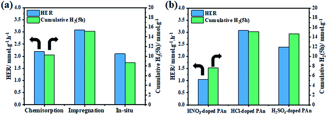 |
| | Fig. 9 The initial and cumulative (5 h) hydrogen evolution rate of (a) TiO2@5PAn composites fabricated by chemisorption, in situ polymerization, and impregnation methods and (b) TiO2@5PAn composites modified with various counterions, NO3−, SO42−, and Cl−. | |
Thereafter, the photocatalytic performance of TiO2@PEDOT, TiO2@PPy, and TiO2@PAn composites with different mass ratios of CPs were estimated as shown in Fig. 10(a–c), whereas Fig. 10(d) displays the activity comparison of optimum composite in each series to pristine TiO2(P25). Simultaneously, the amount H2 produced over pure TiO2 is very low about 86.07 μmol h−1 g−1 which could be ascribed to fast photogenerated charges (e−/h+) recombination, low catalytic active sites and low overpotential, thus significantly takes down the photocatalytic activity. In addition, no hydrogen evolution was detected in the control measurements of CPs. Either because of the negligible amount of hydrogen produced or the pure CPs haven't the capability to photocatalyze water because of the rapid recombination of electron–hole pairs, as confirmed by previous report.55 However, it could be noticed that a remarkable increase in HER after incorporation of a small amount of any of the investigated CPs, in which it increases with increasing the weight ratio. The highest HER performance in every series was observed for TiO2@5PAn of 3.1, whereas for TiO2@2PPy and TiO2@2PEDOT are 2.09, and 1.37 mmol g−1 h−1, respectively. Meanwhile, the amount of evolved hydrogen is improved by 16-fold, 24-fold, and 36-fold while decorating TiO2 with 2PEDOT, 2PPy and 5PAn, respectively. However, further increase past the optimum weight percent decreases the produced hydrogen drastically. This is directly due to lowering the number of active charge carries because of the formation of a surface coverage shell around the photocatalyst which absorbs some of incident light irradiation and possible overlapping occurred into catalytic active sites, resulting in decreasing the catalytic activities.56 This was confirmed by measuring the DRS for all the prepared samples with reference to their weight percent as described in Fig. S11.† It is obvious that a blue shift took place with increasing the weight of polymeric materials in the composite which is in accordance with photocatalytic experiments due to the shielding effect. Moreover, the above-mentioned nanocomposite shows the highest photocatalytic activity in hydrogen generation which was much higher than similar material reported lately.39,57 This is due to homogeneity distributions of the CPs thin layer around TiO2 nanoparticles that were accomplished by cautiously controlling their weight ratios during the synthesis and high electron mobility to TiO2 surface. What's more, the TiO2@5PAn has a higher photocatalytic activity than several other recently published TiO2-based photocatalysts in the literature, which are listed in the Table 2.
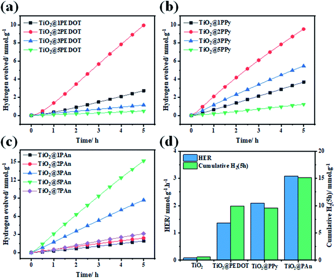 |
| | Fig. 10 Time course of H2 evolution over 50 mg of different weight percent of (a) poly(3,4-ethylenedioxythiophene) (b) polypyrrole (c) polyaniline relative to TiO2 (P25) in a 20% vol. aqueous methanol under UV light irradiation for 5 h (d) Histograms of optimum samples. | |
Table 2 Comparison table on photocatalytic H2 generation activity of TiO2@5PAn with other TiO2-based photocatalysts
| Photocatalyst |
Light source |
Sacrificial agent |
H2 rate (μmol h−1 g−1) |
Ref. (year) |
| PAn/g-TiO2 |
300 W Xe |
Methanol |
1790 |
39 (2017) |
| PAn-TiO2/RGO |
300 W Xe |
Triethanolamine |
806 |
57 (2020) |
| TiO2-RGO |
200 W Xe |
Methanol |
740 |
14 (2012) |
| Ag/RGO/TiO2 |
500 W Xe |
Methanol |
196 |
58 (2014) |
| Ag2NCN/TiO2 |
300 W Xe |
Methanol |
1494 |
59 (2015) |
| Bi2O3/TiO2 |
UV-LEDs |
Glycerol |
920 |
60 (2017) |
| Pt/Oxamide/TiO2 |
300 W Xe |
Triethanolamine |
2370 |
61 (2019) |
| PAn/TiO2 |
UV-LEDs |
Methanol |
3083 |
This work |
| PPy/TiO2 |
UV-LEDs |
Methanol |
2090 |
This work |
| PEDOT/TiO2 |
UV-LEDs |
Methanol |
1370 |
This work |
The recyclability of photocatalysts is an essential parameter to assess the long-term stability of the prepared composites. As some of the photocatalysts degrade from self-oxidation/reduction reactions under light irradiation, leading to a decrease in photocatalytic activity. Therefore, the stability of the prepared samples under light irradiation was examined for a total time of 20 h, segmented into 4 cycles of 5 h each as shown in Fig. 11. As revealed, all composites remained almost unchanged after four consecutive cycles of light irradiation. Consequently, this demonstrates efficient and excellent stability of the prepared composites for H2 production for a long time. Besides that, the chemical structure of the as-fabricated composites remained basically unchanged as revealed by FTIR and DRS spectra as shown in Fig. 11(b and c). All the characteristic FTIR absorption bands of investigated CPs backbone appeared, which proves the photo and chemical stability of the prepared composite.
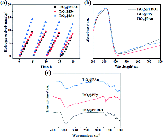 |
| | Fig. 11 (a) Cyclic photocatalytic hydrogen generation over 50 mg of TiO2@PEDOT, TiO2@PPy, and TiO2@PAn in 20% (vol.) methanol aqueous solutions under UV light illumination (λ = 365 nm), (b) DRS, and (c) FTIR spectra TiO2@2PEDOT, TiO2@2PPy, and TiO2@5PAn composites after 20 h of light irradiation. | |
3.8. Photoelectrochemical measurements
Since reducing the recombination rate of photogenerated electron/hole pairs is the key factor for maximizing photocatalytic activity. We have found that the deposition method has an effective role in forming an intimate contact at the surface between CPs and TiO2, thus the performance of the prepared composite. Consequently, we have conducted the PEC measurements as well as photoluminescence (PL) emission spectrum to evaluate the charge separation efficiency of TiO2@PAn composites prepared by various methods as shown in Fig. 12. Among all the presented photocatalysts, TiO2@PAn synthesized via impregnation method showed higher photocurrent response and lower semicircle radius of EIS Nyquist plot compared to the composites prepared by other methods as shown in Fig. 12(a and b). This could be explained based on the lower charge transfer resistance of TiO2@PAn synthesized via impregnation method thus better charge separation. Moreover, the lower intensity of the PL spectra of TiO2@PAn_Imp composite (Fig. 12c) further confirms that the composite prepared by the impregnation deposition method exhibited better separation and migration of charge carriers, thereby efficient photocatalytic performance. Furthermore, the deposition method could improve the direct contact between host photocatalyst and cocatalyst at the surface. Also, the catalytic activity was evaluated by cyclic voltammetry technique (Fig. 12d), where the TiO2@PAn_Imp showed the highest cathodic current compared to TiO2@PAn_Insitu and TiO2@PAn_Ads composites. The obtained results are consistent with the photoproduction H2 experiments, implying that the impregnation method are the most effective method for higher photocatalytic performance. Electrical conductivity of conducting polymers (CPs) can be transferred from insulating states to be conductive or semi-conductive materials via doping process. The doping mechanism of PAn by protonic acids is shown in Fig. S12.† Briefly, protonation reaction occurs on the N atoms and then charge of N atoms is delocalized to the neighboring benzene ring and N atoms by conjugation. Therefore, we have investigated the charge transfer resistance of polyaniline doped with the different counterions (Cl−, SO42−, and NO3−) via EIS test. Semicircle radius of Nyquist plot from the EIS measurements is directly linked with the charge transfer resistance (conductivity) of the samples. We have found that the TiO2@PAn-doped HCl composite showed the lowest charge transfer resistance compared to HNO3 and H2SO4 doping as shown in (Fig. S13†). This indicates that PAn doped with chloride ion has higher conductivity compared to nitrate and sulfate ions.
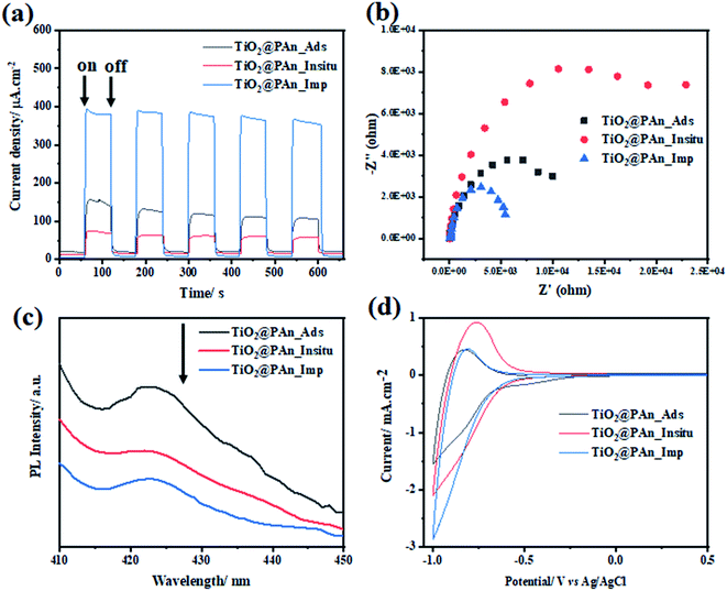 |
| | Fig. 12 (a) Transient photocurrent response (I–t) curves; (b) EIS Nyquist plots under light irradiation; (c) the photoluminescence spectra (PL) measured at an excitation wavelength of 350 nm, and (d) cyclic voltammetry curves of TiO2@PAn_Insitu TiO2@PAn_Ads, and TiO2@PAn_Imp photocatalysts. | |
In order to investigate the suppression efficiency of photoexcited charges recombination, the chronoamperometric (I–t) curves of the obtained photoelectrodes were all measured at a fixed applied potential of 0.6 V under on/off cycles of UV light irradiation in an 0.1 M Na2SO4 (pH = 7) electrolyte solution. As shown in Fig. 13(a), the photocurrent response increases rapidly when light is turned on and diminishes once it is turned off. The photocurrent transient intensities of TiO2@2PEDOT, TiO2@2PPy and TiO2@5PAn electrodes were found to be 80, 354 and 396 μA cm−2, respectively, which represents 3, 12 and 14 times increase from that of pure TiO2 under continuously intermittent on/off light irradiation. Also, the fast photocurrent response under continuous on/off light irradiation demonstrates the well-formed heterojunction between CPs and TiO2. Additionally, no clearly observed decay in current intensity for all samples which exhibit reproducible photocurrent response, indicating superior stability under light illumination. The relative low photocurrent density of unmodified TiO2 could be attributed to the high recombination of electron–hole pairs. The photocurrent transient response of TiO2@2PEDOT, TiO2@2PPy and TiO2@5PAn electrodes was evaluated for long time under UV-irradiation to assess their photo and chemical stability as presented in Fig. S14.† No noticeable decrease in the current density after exposure to light irradiation for over 100 min, implying sufficient photostability of the prepared composite. Furthermore, Fig. 13(b) shows the Nyquist plot of the samples acquired from EIS measurements under light irradiation as an effective technique to evaluate the recombination rates via measuring the charge transfer resistance. Form this test we could elucidate the conductivity which is linked to the semicircle radius. We have found that the bare TiO2 has the highest semi-circular radius, indicating its inefficient separation of e−/h+ pairs. On the other hand, a sharp decrease in the semi-circle radius for TiO2@2PPy, TiO2@2PEDOT photocatalysts based electrodes was observed, whereas the smallest value obtained was for TiO2@5PAn. This could be attributed to its excellent conductivity and high ability of the photogenerated charge carriers to transfer across the heterojunction interface. The proposed equivalent circuit was introduced according to the diffusion–recombination model,62 and the fitting results are summarized in Table S1.† It was found that the modification of bare-TiO2 with CPs remarkably enhanced the electrical conductivity thus decrease the recombination of e−/h+ pairs. A strong emission at 420 nm, due to the fast recombination of photogenerated charge carries, was shown in PL spectrum of bare TiO2 (Fig. 13c). The deposition of CPs as cocatalysts resulting in decreasing the intensity of the emission peak, and the TiO2@PAn photocatalyst achieved the lowest intensity of all fabricated samples. The obtained results from EIS are consistent with the PL spectra, confirming that the modification with CPs composites enhancing the photocatalytic performance through effective inhibition of charges recombination. This observation is in accordance with results obtained from photocatalytic hydrogen production experiments. Therefore, conducting polymers could be regarded as efficient cocatalysts that play a valuable role in the enhancement of surface redox reactions. Further, cyclic voltammetry measurements were performed to measure the cathodic current and asses the activity of the catalytic reduction sites as presented in Fig. 13d. The obtained cathodic current enhanced significantly through the incorporation of CPs, where the values of the measured reduction current measured for TiO2, TiO2@2PEDOT, TiO2@2PPy and TiO2@5PAn are 0.93, 2.13, 2.02 and 2.84 mA cm2, respectively. Also, a clear negative shift of the onset potential was observed. The remarkable shift of the onset potential results in enhancing the photocatalytic performance and confirming the formation of p–n heterostructure.63
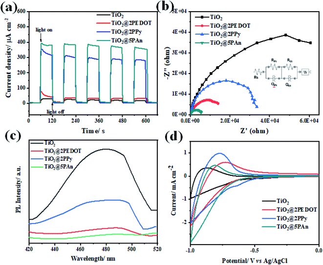 |
| | Fig. 13 (a) Transient photocurrent response (I–t) curves; (b) EIS Nyquist plots; (c) the photoluminescence spectra (PL) measured at an excitation wavelength of 350 nm and (d) cyclic voltammetry curves of TiO2, TiO2@2PEDOT, TiO2@2PPy, and TiO2@5PAn, photocatalysts. | |
The HOMO and LUMO energy levels of some CPs were investigated electrochemically via cyclic voltammetry (CV).64,65 Both studies have conducted CV in the presence of ferrocene/ferrocenium (Fc/Fc+) redox couples with 0.1 M Bu4N+PF6−/acetonitrile solution as the internal standard and used the onset potentials of the first oxidation peak and first reduction peak. Fig. 14 shows the CV scans of the investigated CPs (PANI, PPy, PEDOT) with a scan rate of 20 mV s−1 in 0.1 M Na2SO4 as the electrolyte solution. The energy levels can be calculated using the following empirical formulas:
| EHOMO = −(Eox.onset vs. Ag/AgCl + 4.8) eV |
| ELUMO = −(Ered.onset vs. Ag/AgCl + 4.8) eV |
The onset voltage of reduction and oxidation for PAn, PPy, and PEDOT were found to be −0.88, −0.82, −0.69 and 1.06, 0.96, 0.64 V, respectively (
vs. Ag/AgCl). Therefore, the HOMO and LUMO levels were estimated to be −5.86, −5.76, −5.44 and −3.92, −3.98, −4.11 eV, respectively (
versus vacuum level). Moreover, the band gap edge positions of the valence band (VB) and conduction band (CB) of a TiO
2 can be calculated by the following equation:
66Here,
X is the absolute electronegativity of TiO
2 (5.82 eV),
Ee is the energy of free electrons on the hydrogen scale (likely 4.5 eV), and
Eg is the optical band gap (3.0 eV). Based on these calculations, the VB and CB of TiO
2 are −7.32 and −4.32 eV
versus vacuum, respectively. Accordingly, the energy band structure of the TiO
2@CPs photocatalysts could be represented as shown in
Fig. 15.
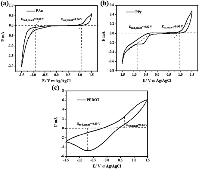 |
| | Fig. 14 (a–c) Cyclic voltammetry (CV) curves of pure PAn, PPy and PEDOT conducting polymers electrodes. | |
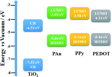 |
| | Fig. 15 Energy band structure of TiO2@PEDOT, TiO2@PPy, and TiO2@PAn photocatalysts. | |
Furthermore, the type of semiconductor and band potential of the photocatalysts are essential parameters for engineering the heterojunction. Consequently, the electrochemical Mott–Schottky plots were recorded at a fixed frequency of 1 kHz without light irradiation. The capacitance is a function of applied potential which can be expressed mathematically as follows:
where, the positive slope can be assigned to n-type and the negative to the p-type semiconductors. As revealed in Fig. S15,
† the negative and positive slope values suggest the p-type and n-type semiconductor of CPs and TiO
2, respectively.
67 Since CPs could be regarded as p-type semiconductors as reported elsewhere,
68–70 and verified experimentally, they are expected to have a good ability for transporting holes with excellent conductivity. Specifically, the measured flat band potential of PAn and TiO
2 were 0.87 and −0.18 V
vs. Ag/AgCl, respectively, confirming the spontaneous electron transport in the prepared composite. Hence, the photogenerated electrons with higher energy in PAn chains would transfer through the interface to the surface of TiO
2 photocatalyst.
3.9. Photocatalytic mechanism
In general, the enhancement of photocatalytic H2 generation over TiO2-based CPs composites could be attributed to two major reasons: First, the inhibition of recombination of the photogenerated electron–hole pairs throughout efficient electron transfers at the surface interface due to high conductivity. Second, the increase in the light harvesting ability of photocatalyst composite via photosensitization effect. To further illustration, the proposed mechanism of TiO2@5PAn nanocomposite are schematically presented in Fig. 11. As has been shown in Fig. 16, the highest occupied molecular orbital (HOMO) of polyaniline is placed in between the valence (VB) and conduction (CB) bands of TiO2, whereas the lowest unoccupied molecular orbital (LUMO) is located higher than the CB as experimentally verified and reported elsewhere.71 Upon the UV light excitation, an electron (e−) jumps from VB to CB and a hole (h+) is generated in VB which is trapped/consumed by help of a hole scavenger i.e. methanol. The photoexcited electron species can migrate to catalytic surface active sites where they reduce the protons to evolve hydrogen. At the same time, the PAn hydride materials may absorb light photons to induce π–π* electron transitions from HOMO to LUMO which are quickly injected into the CB of the photocatalyst. Moreover, in TiO2-based CPs systems, due to excellent intrinsic conductivity, CPs take the role of extracting and trapping the photoexcited charge carries at the interface contact point on TiO2 surface to inhibit the recombination process and also may provide extra catalytic active sites. What's more, they can produce electrons under sunlight excitation and introduce them into the conduction bands of the corresponding photocatalyst. This facilitates the catalytic activity and improves photocatalytic performance.
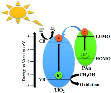 |
| | Fig. 16 Scheme illustrating the photocatalytic hydrogen production via water splitting over TiO2@PAn heterostructure. | |
4. Conclusion
In summary, optimized TiO2@PEDOT, TiO2@PPy, and TiO2@PAn photocatalyst composites have been successfully fabricated by means of the incipient wet impregnation method. The as prepared composites were characterized by SEM, TEM, XRD, N2-physisorption, DRS and TGA. The effect of the deposition method on the photocatalytic performance were evaluated. The results obtained from diffuse reflectance spectroscopy (DRS) showed decrease in optical band gap and hence enlarging the light absorption coefficient to the visible region. Besides that, an efficient performance in the suppression of the recombination of the photogenerated electron–hole pairs was confirmed by photoelectrochemical techniques. The photocatalytic performance of the as-synthesized nanocomposites was evaluated for H2 production using methanol as sacrificial electron donor under UV illumination. Interestingly, all the modified heterostructures exhibited remarkable enhancement in photocatalytic activity than commercial P25. The photocatalytic experiments indicate that the optimum percent weights for PEDOT, PPy, and PAn loadings were 2%, 2%, and 5% with HER of 1.39, 2.09, and 3.04 mmol h−1 g−1, respectively. According to this comparative investigation, TiO2@5PAn could be stated as the most active photocatalyst for H2 evolution even higher than several other lately reported TiO2-based composites with the same composition. The main purpose of this study is to highlight the effect of the incorporation of different types of coducting polymers as cheap and efficient matrix with semiconductor photocatalysts to enhance the photocatalytic performance.
Conflicts of interest
There are no conflicts to declare.
Acknowledgements
This work was supported by the Science, Technology & Innovation Funding Authority (STIFA) in Egypt as part of research project (ID 41623 and 43281). The authors are very grateful to Institutional Review Board (IRB) of the Faculty of Science at Assiut University, Egypt. The first author is indebted to Prof. Ahmed Geies, former Assiut University president, for his support to build the experimental set up. The authors are also thankful to Dr Ahmed A. K. Mohamed for English revision.
References
- C. McGlade and P. Ekins, Nature, 2015, 517, 187–190 CrossRef CAS PubMed.
- A. Tawfik, H. El-Bery, M. Elsamadony, S. Kumari and F. Bux, Int. J. Energy Res., 2019, 43, 3516–3527 CrossRef CAS.
- D. McDowall, B. J. Greeves, R. Clowes, K. McAulay, A. M. Fuentes-Caparrós, L. Thomson, N. Khunti, N. Cowieson, M. C. Nolan, M. Wallace, A. I. Cooper, E. R. Draper, A. J. Cowan and D. J. Adams, Adv. Energy Mater., 2020, 10, 2002469 CrossRef CAS.
- A. Fujishima and K. Honda, Nature, 1972, 238, 37–38 CrossRef CAS PubMed.
- T. S. Teets and D. G. Nocera, Chem. Commun., 2011, 47, 9268–9274 RSC.
- X. Chen, S. Shen, L. Guo and S. S. Mao, Chem. Rev., 2010, 110, 6503–6570 CrossRef CAS PubMed.
- D. V. Markovskaya, S. V. Cherepanova, E. Y. Gerasimov, A. V. Zhurenok, A. V. Selivanova, D. S. Selishchev and E. A. Kozlova, RSC Adv., 2020, 10, 1341–1350 RSC.
- M. Kim, A. Razzaq, Y. K. Kim, S. Kim and S.-I. In, RSC Adv., 2014, 4, 51286–51293 RSC.
- Y. Gao, H. Lin, S. Zhang and Z. Li, RSC Adv., 2016, 6, 6072–6076 RSC.
- H. Li, B. Sun, F. Yang, Z. Wang, Y. Xu, G. Tian, K. Pan, B. Jiang and W. Zhou, RSC Adv., 2019, 9, 7870–7877 RSC.
- M. Sun, Y. Jiang, M. Tian, H. Yan, R. Liu and L. Yang, RSC Adv., 2019, 9, 11443–11450 RSC.
- D. Gao, W. Liu, Y. Xu, P. Wang, J. Fan and H. Yu, Appl. Catal., B, 2020, 260, 118190 CrossRef CAS.
- K. Kočí, M. Reli, M. Edelmannová, I. Troppová, H. Drobná, A. Rokicińska, P. Kuśtrowski, D. Dvoranová and L. Čapek, J. Photochem. Photobiol., A, 2018, 366, 55–64 CrossRef.
- M. S. A. Sher Shah, A. R. Park, K. Zhang, J. H. Park and P. J. Yoo, ACS Appl. Mater. Interfaces, 2012, 4, 3893–3901 CrossRef CAS PubMed.
- H. M. El-Bery, Y. Matsushita and A. Abdel-moneim, Appl. Surf. Sci., 2017, 423, 185–196 CrossRef CAS.
- R. Abe, K. Sayama and H. Arakawa, Chem. Phys. Lett., 2002, 362, 441–444 CrossRef CAS.
- L. Wang, Z. Gao, Y. Li, H. She, J. Huang, B. Yu and Q. Wang, Appl. Surf. Sci., 2019, 492, 598–606 CrossRef CAS.
- C. Kirchner, T. Liedl, S. Kudera, T. Pellegrino, A. Muñoz Javier, H. E. Gaub, S. Stölzle, N. Fertig and W. J. Parak, Nano Lett., 2005, 5, 331–338 CrossRef CAS PubMed.
- G. Hodes, J. Phys. Chem. C, 2008, 112, 17778–17787 CrossRef CAS.
- H. Shirakawa, E. J. Louis, A. G. MacDiarmid, C. K. Chiang and A. J. Heeger, J. Chem. Soc., Chem. Commun., 1977, 578–580 RSC.
- J. Jayakumar and H. Chou, ChemCatChem, 2020, 12, 689–704 CrossRef CAS.
- H. Li, M. R. Gadinski, Y. Huang, L. Ren, Y. Zhou, D. Ai, Z. Han, B. Yao and Q. Wang, Energy Environ. Sci., 2020, 13, 1279–1286 RSC.
- N. S. Hudak, J. Phys. Chem. C, 2014, 118, 5203–5215 CrossRef CAS.
- G. A. Snook, P. Kao and A. S. Best, J. Power Sources, 2011, 196, 1–12 CrossRef CAS.
- K. Saranya, M. Rameez and A. Subramania, Eur. Polym. J., 2015, 66, 207–227 CrossRef CAS.
- A. F. M. EL-Mahdy, A. M. Elewa, S.-W. Huang, H.-H. Chou and S.-W. Kuo, Adv. Opt. Mater., 2020, 8, 2000641 CrossRef CAS.
- W.-H. Wang, L.-Y. Ting, J. Jayakumar, C.-L. Chang, W.-C. Lin, C.-C. Chung, M. H. Elsayed, C.-Y. Lu, A. M. Elewa and H.-H. Chou, Sustainable Energy Fuels, 2020, 4, 5264–5270 RSC.
- Y. Bai, D. J. Woods, L. Wilbraham, C. M. Aitchison, M. A. Zwijnenburg, R. S. Sprick and A. I. Cooper, J. Mater. Chem. A, 2020, 8, 8700–8705 RSC.
- M. H. Elsayed, J. Jayakumar, M. Abdellah, T. H. Mansoure, K. Zheng, A. M. Elewa, C.-L. Chang, L.-Y. Ting, W.-C. Lin and H. Yu, Appl. Catal., B, 2020, 283, 119659 CrossRef.
- D. Svirskis, J. Travas-Sejdic, A. Rodgers and S. Garg, J. Controlled Release, 2010, 146, 6–15 CrossRef CAS PubMed.
- N. Dubey and M. Leclerc, J. Polym. Sci., Part B: Polym. Phys., 2011, 49, 467–475 CrossRef CAS.
- F. Heshmatpour and S. Zarrin, J. Photochem. Photobiol., A, 2017, 346, 431–443 CrossRef CAS.
- C.-J. Chang and K.-W. Chu, Int. J. Hydrogen Energy, 2016, 41, 21764–21773 CrossRef CAS.
- Z. Zhao, Y. Zhou, W. Wan, F. Wang, Q. Zhang and Y. Lin, Mater. Lett., 2014, 130, 150–153 CrossRef CAS.
- Y. Tan, Y. Chen, Z. Mahimwalla, M. B. Johnson, T. Sharma, R. Brüning and K. Ghandi, Synth. Met., 2014, 189, 77–85 CrossRef CAS.
- D. Wang, Y. Wang, X. Li, Q. Luo, J. An and J. Yue, Catal. Commun., 2008, 9, 1162–1166 CrossRef CAS.
- J. Stejskal and R. G. Gilbert, Pure Appl. Chem., 2002, 74, 857–867 CAS.
- Y. Xia, K. Sun and J. Ouyang, Adv. Mater., 2012, 24, 2436–2440 CrossRef CAS PubMed.
- S. Xu, Y. Han, Y. Xu, H. Meng, J. Xu, J. Wu, Y. Xu and X. Zhang, Sep. Purif. Technol., 2017, 184, 248–256 CrossRef CAS.
- M. Gao, J. Wang, Y. Zhou, P. He, Z. Wang and S. Zhao, J. Appl. Polym. Sci., 2020, 137, 49049 CrossRef CAS.
- R. Megha, Y. T. Ravikiran, S. C. Vijaya Kumari, H. G. Rajprakash, S. Manjunatha, M. Revanasiddappa, M. Prashantkumar and S. Thomas, Mater. Sci. Semicond. Process., 2020, 110, 104963 CrossRef CAS.
- X. Liu, H. Lai, J. Li, G. Peng, Z. Yi, R. Zeng, M. Wang and Z. Liu, Int. J. Hydrogen Energy, 2019, 44, 4698–4706 CrossRef CAS.
- S. Khasim, A. Pasha, N. Badi, M. Lakshmi and Y. K. Mishra, RSC Adv., 2020, 10, 10526–10539 RSC.
- H. Zhang, R. Zong, J. Zhao and Y. Zhu, Environ. Sci. Technol., 2008, 42, 3803–3807 CrossRef CAS PubMed.
- Y. Zou, Q. Wang, D. Jiang, C. Xiang, H. Chu, S. Qiu, H. Zhang, F. Xu, L. Sun and S. Liu, Ceram. Int., 2016, 42, 8257–8262 CrossRef CAS.
- H. Zhang and Y. Zhu, J. Phys. Chem. C, 2010, 114, 5822–5826 CrossRef CAS.
- H. Zhang, R. Zong, J. Zhao and Y. Zhu, Environ. Sci. Technol., 2008, 42, 3803–3807 CrossRef CAS PubMed.
- C. Han, P. Dong, H. Tang, P. Zheng, C. Zhang, F. Wang, F. Huang and J.-X. Jiang, Chem. Sci., 2021, 12, 1796–1802 RSC.
- C. M. Aitchison, M. Sachs, M. A. Little, L. Wilbraham, N. J. Brownbill, C. M. Kane, F. Blanc, M. A. Zwijnenburg, J. R. Durrant and R. S. Sprick, Chem. Sci., 2020, 11, 8744–8756 RSC.
- P. Makuła, M. Pacia and W. Macyk, J. Phys. Chem. Lett., 2018, 9, 6814–6817 CrossRef PubMed.
- R. J. Vimal Michael, J. Theerthagiri, J. Madhavan, M. J. Umapathy and P. T. Manoharan, RSC Adv., 2015, 5, 30175–30186 RSC.
- X. Li, W. Chen, C. Bian, J. He, N. Xu and G. Xue, Appl. Surf. Sci., 2003, 217, 16–22 CrossRef CAS.
- F. Deng, L. Min, X. Luo, S. Wu and S. Luo, Nanoscale, 2013, 5, 8703–8710 RSC.
- H. Shi, C. Liu, Q. Jiang and J. Xu, Adv. Electron. Mater., 2015, 1, 1500017 CrossRef.
- Q. Zhou and G. Shi, J. Am. Chem. Soc., 2016, 138, 2868–2876 CrossRef CAS PubMed.
- M. Bowker, D. James, P. Stone, R. Bennett, N. Perkins, L. Millard, J. Greaves and A. Dickinson, J. Catal., 2003, 217, 427–433 CrossRef CAS.
- J. Ma, J. Dai, Y. Duan, J. Zhang, L. Qiang and J. Xue, Renewable Energy, 2020, 156, 1008–1018 CrossRef CAS.
- W. Gao, M. Wang, C. Ran, X. Yao, H. Yang, J. Liu, D. He and J. Bai, Nanoscale, 2014, 6, 5498 RSC.
- H. Meng, X. Li, X. Zhang, Y. Liu, Y. Xu, Y. Han and J. Xu, Dalton Trans., 2015, 44, 19948–19955 RSC.
- D. Xu, Y. Hai, X. Zhang, S. Zhang and R. He, Appl. Surf. Sci., 2017, 400, 530–536 CrossRef CAS.
- J. Shen, R. Wang, Q. Liu, X. Yang, H. Tang and J. Yang, Chin. J. Catal., 2019, 40, 380–389 CrossRef CAS.
- R. Bashiri, M. F. R. Samsudin, N. M. Mohamed, N. A. Suhaimi, L. Y. Ling, S. Sufian and C. F. Kait, Appl. Surf. Sci., 2020, 510, 145482 CrossRef CAS.
- K. Fujii, M. Ono, Y. Iwaki, K. Sato, K. Ohkawa and T. Yao, J. Phys. Chem. C, 2010, 114, 22727–22735 CrossRef CAS.
- C. M. Cardona, W. Li, A. E. Kaifer, D. Stockdale and G. C. Bazan, Adv. Mater., 2011, 23, 2367–2371 CrossRef CAS PubMed.
- C. Wang, Z.-Y. Hu, H. Zhao, W. Yu, S. Wu, J. Liu, L. Chen, Y. Li and B.-L. Su, J. Colloid Interface Sci., 2018, 521, 1–10 CrossRef CAS PubMed.
- X. Lin, J. Xing, W. Wang, Z. Shan, F. Xu and F. Huang, J. Phys. Chem. C, 2007, 111, 18288–18293 CrossRef CAS.
- Y. Chen, Z. Qin, X. Wang, X. Guo and L. Guo, RSC Adv., 2015, 5, 18159–18166 RSC.
- M. Rouhi, M. Babamoradi, Z. Hajizadeh, A. Maleki and S. T. Maleki, Optik, 2020, 212, 164721 CrossRef CAS.
- A. Savateev, Y. Markushyna, C. M. Schüßlbauer, T. Ullrich, D. M. Guldi and M. Antonietti, Angew. Chem., 2021, 133, 7512–7520 CrossRef.
- N. A. Jumat, P. S. Wai, J. J. Ching and W. J. Basirun, Polym. Polym. Compos., 2017, 25, 507–514 CAS.
- D. Hidalgo, S. Bocchini, M. Fontana, G. Saracco and S. Hernández, RSC Adv., 2015, 5, 49429–49438 RSC.
- D. Heggo, H. M. El-Bery, S. Ookawara and Y. Matsushita, J. Chem. Eng. Jpn., 2016, 49(2), 130–135 CrossRef CAS.
- S. Nabil, A. S. Hammad, H. M. El-Bery, E. A. Shalaby and A. H. El-Shazly, Environ. Sci. Pollut. Res., 2021 DOI:10.1007/s11356-021-13090-7.
Footnote |
| † Electronic supplementary information (ESI) available. See DOI: 10.1039/d1ra01218e |
|
| This journal is © The Royal Society of Chemistry 2021 |
Click here to see how this site uses Cookies. View our privacy policy here.  Open Access Article
 *a,
Mahmoud R. Salaha,
Seddique M. Ahmedb and
Soliman A. Solimanb
![[thin space (1/6-em)]](https://www.rsc.org/images/entities/char_2009.gif) :
:![[thin space (1/6-em)]](https://www.rsc.org/images/entities/char_2009.gif) 2) were used) were added dropwise under continuous stirring from burette for about 1 h. Subsequently, the polymerization was performed by stirring the reactants solution in the ice bath for more 6 h. Afterwards, the obtained precipitates were vacuum filtered, and washed several times with 1 M HCl, distilled water and methanol till discoloration of the filtrate, then dried for 24 h at 60 °C till constant mass. The dried PPy and PAn was fine grounded using agate mortar and then used. The systematic illustration of stepwise preparation of PAn and PPy described in Fig. S1.† Similarly, the polyaniline doped with different counter ions, NO3− and SO42−, were prepared by the same abovementioned procedure but HCl was replaced with HNO3 and H2SO4, respectively.
2) were used) were added dropwise under continuous stirring from burette for about 1 h. Subsequently, the polymerization was performed by stirring the reactants solution in the ice bath for more 6 h. Afterwards, the obtained precipitates were vacuum filtered, and washed several times with 1 M HCl, distilled water and methanol till discoloration of the filtrate, then dried for 24 h at 60 °C till constant mass. The dried PPy and PAn was fine grounded using agate mortar and then used. The systematic illustration of stepwise preparation of PAn and PPy described in Fig. S1.† Similarly, the polyaniline doped with different counter ions, NO3− and SO42−, were prepared by the same abovementioned procedure but HCl was replaced with HNO3 and H2SO4, respectively.
![[double bond, length as m-dash]](https://www.rsc.org/images/entities/char_e001.gif) C stretching modes in a benzenoid unit, respectively. Moreover, benzene structure of C–N stretching vibration peak at 1293 cm−1, quinonoid structure of C–N stretching vibration peak at 1240 cm−1.40 While, in the case of PPy, the absorption bands at 1188 and 1555 cm−1 could be attributed to N–C stretching, and the ring stretching mode of pyrrole.41 To further confirm the existence of CPs in the as-prepared samples, the FTIR spectra of bare and modified TiO2 were conducted as presented in Fig. 3b. The broad band appears at 3500 cm−1 is indexed to ν(OH) of physically adsorbed water molecules on the composite surface. Also, the band at 1650 cm−1 in the spectrum of bare-TiO2 could be indexed to O–H stretching vibration, indicating the presence of hydrogen-bonding. For TiO2@PAn nanocomposites, multiple absorption bands were obtained at 1130, 1500, and 1590 cm−1, proving the incorporation of PAn backbone. The observed shift toward higher wavenumbers, indicating the significant interactions between TiO2 and polymers chains which is favorable for the electron transfer process.42 In the same way, for TiO2@PPy, the characteristic band of the PPy ring appeared at 1480, 1550, and 1178 cm−1. Also, the bands at 1180 and 1620 cm−1 in the spectrum of TiO2@PEDOT are attributed to C–C and C
C stretching modes in a benzenoid unit, respectively. Moreover, benzene structure of C–N stretching vibration peak at 1293 cm−1, quinonoid structure of C–N stretching vibration peak at 1240 cm−1.40 While, in the case of PPy, the absorption bands at 1188 and 1555 cm−1 could be attributed to N–C stretching, and the ring stretching mode of pyrrole.41 To further confirm the existence of CPs in the as-prepared samples, the FTIR spectra of bare and modified TiO2 were conducted as presented in Fig. 3b. The broad band appears at 3500 cm−1 is indexed to ν(OH) of physically adsorbed water molecules on the composite surface. Also, the band at 1650 cm−1 in the spectrum of bare-TiO2 could be indexed to O–H stretching vibration, indicating the presence of hydrogen-bonding. For TiO2@PAn nanocomposites, multiple absorption bands were obtained at 1130, 1500, and 1590 cm−1, proving the incorporation of PAn backbone. The observed shift toward higher wavenumbers, indicating the significant interactions between TiO2 and polymers chains which is favorable for the electron transfer process.42 In the same way, for TiO2@PPy, the characteristic band of the PPy ring appeared at 1480, 1550, and 1178 cm−1. Also, the bands at 1180 and 1620 cm−1 in the spectrum of TiO2@PEDOT are attributed to C–C and C![[double bond, length as m-dash]](https://www.rsc.org/images/entities/char_e001.gif) C bonds of the thiophene ring.43 Low intensities of CPs absorption bands due to their relatively low contents in the as-prepared composites. However, we could conclude the successful incorporation of CPs in the as-fabricated samples.
C bonds of the thiophene ring.43 Low intensities of CPs absorption bands due to their relatively low contents in the as-prepared composites. However, we could conclude the successful incorporation of CPs in the as-fabricated samples.


