
 Open Access Article
 This Open Access Article is licensed under a Creative Commons Attribution-Non Commercial 3.0 Unported Licence
Shape transformation and self-alignment of Fe-based nanoparticles†
Jeongmin
Hong
 *ab,
Qiang
Luo
a,
Daesung
Jung
c,
Soong-Geun
Je
d,
Yooseok
Kim
e,
Mi-Young
Im
d,
Chan-Cuk
Hwang
c,
Sakhrat
Khizroev
f,
Seungjun
Chung
g and
Long
You
a
*ab,
Qiang
Luo
a,
Daesung
Jung
c,
Soong-Geun
Je
d,
Yooseok
Kim
e,
Mi-Young
Im
d,
Chan-Cuk
Hwang
c,
Sakhrat
Khizroev
f,
Seungjun
Chung
g and
Long
You
a
aSchool of Optical and Electronic Information, Huazhong University of Science and Technology, Wuhan 430074, PR China. E-mail: jehong@hust.edu
bResearch and Development Division, JS Nanotechnologies LLC, San Jose, CA 95134, USA
cPohang Accelerator Laboratory (PAL), Pohang University of Science and Technology, Pohang 37673, South Korea
dCenter for X-ray Optics, Lawrence Berkeley National Laboratory, Berkeley, CA 94720, USA
eWONIK IPS Co. Ltd., Pyeongtaek 17709, South Korea
fElectrical and Computer Engineering, University of Miami, Coral Gables, FL 33146, USA
gPhoto-Electronic Hybrids Research Center, Korea Institute of Science and Technology, Seoul 02792, South Korea
First published on 16th May 2019
Abstract
New types of functional material structures will emerge if the shape and properties are controlled in three-dimensional nanodevices. Possible applications of these would be nanoelectronics and medical systems. Magnetic nanoparticles (MNPs) are especially important in electronics such as magnetic storage, sensors, and spintronics. Also, in those that are used as magnetic resonance imaging contrasts, and tissue specific therapeutic agents, as well as in the labeling and sorting of cells, drug delivery, separation of biochemical products, and in other medical applications. Most of these applications require MNPs to be chemically stable, uniform in size, and controllable in terms of their magnetic properties and shape. In this paper three new functions of iron (Fe)-based nanoparticles are reported: shape transformation, oxidation prevention, and self-alignment. The shape of the Fe nanoparticles could be controlled by changing their oxidation states and properties by using a nanocarbon coating. Full field X-ray microscopy using synchrotron radiation revealed controllable magnetic properties of MNPs at the L3 edge which depended on the oxidation states. Then, inkjet printing was successfully performed to deposit a uniform layer of MNPs by the size.
Introduction
Recent developments of nanoparticles (NPs) have been found in chemistry, physics, biosciences, materials' science, and many others.1–10 Because of the widespread applications of magnetic nanoparticles (MNPs) in biotechnology, materials' science, engineering, and environmental studies, much attention has been paid to the controllable synthesis of different types of MNPs.11,12 The applications of interest are: ferrofluids, recording media, magnetic refrigeration, magnetic resonance imaging, drug delivery, cancer therapy, and many others.11–17The MNPs usually exhibit superparamagnetic behaviour because of their infinitely small coercivity as their sizes are reduced down to the sub-10 nm range. For example, one of the important applications of superparamagnetic NPs is their use as drug-delivery agents to overcome the blood–brain barrier under controllable magnetic fields.18,19 However, MNPs tend to aggregate into large clusters, and thus, lose specific properties associated with single domain magnetic nanostructures.20 Therefore, a new, efficient approach to achieve adequately controllable magnetic properties of MNPs needs to be found.
Iron (Fe) shows superior magnetic properties which are important for spintronics and medical applications. However, it is easily oxidized, which changes its physical properties, by using phase transitions. Pure Fe NPs covered by nanocarbon shell structures such as carbon nanotubes (CNTs) and graphene could not only protect the oxidation, but manipulate the carbon's own properties.21 The production of pure Fe NPs is challenging, but after systematic synthesis of a nanocarbon shell, the properties of Fe can present without further oxidation.22,23 The use of the superior properties of nanocarbon structures and interfaces could be useful for many applications because of the magneto-electric effects.24–26
Although the use of NPs in solution can be controlled well, MNPs are very challenging to align in a dry form because of its interactions between each particle.24 Drop casting and spray methods are very commonly used to deposit MNPs onto substrates. Using inkjet printing technology it is possible to align MNPs in multiple dimensions. Printing of MNPs makes it possible to align them in two-dimensional and three-dimensional (3D) structures if it is deposited in a controllable way.27 Using the optimal conditions for inkjet printing, a drop of the liquid's suspended particulate matter is deposited to form a ring on the substrate. These effects could control the alignment of a same size distribution of the NPs because of the fluid dynamics.
In this paper, a unique way to modulate MNPs by controlling the size, shape, and magnetic properties is presented. To prevent oxidation, a nanocarbon shell was used to cover Fe structures. For oxides and pure Fe states, the magnetic properties of the nanocarbon have not been well studied using characterizing magnetometry.28,29 Magnetic microscopy such as magnetic force microscopy limits phase imaging because of its topographical effects on the MNPs as described in the ESI.† Using synchrotron radiation, full field X-ray microscopy was successfully performed to present element specific magnetic imaging using X-ray magnetic circular dichroism (XMCD). The Fe-based particle imaging could distinguish pure Fe and Fe–O at the L3 edge. Then, the particles were printed onto rigid, and even flexible, substrates using inkjet printing technology.
Results and discussion
Fe–O synthesis
The synthesis started with magnetic NPs obtained using a conventional method.29 The size of the magnetic NPs varied from 5 nm to 200 nm as shown in Fig. 1. From the results of the coagulation experiment, it was found that the particles coagulated very easily by applying a magnetic field. The coagulation of MNPs was a more stable if the coagulation stabilized. When the fabrication conditions such as pH and process temperature were changed, the particles transformed to other stable forms of iron oxide, such as maghemite (γ-Fe2O3) and hematite (α-Fe2O3). Five types of shape transformation of MNPs were observed: pyramidal, square, hybrid (coexisting with circular and square structures), and oval structures as reported previously in the literature.30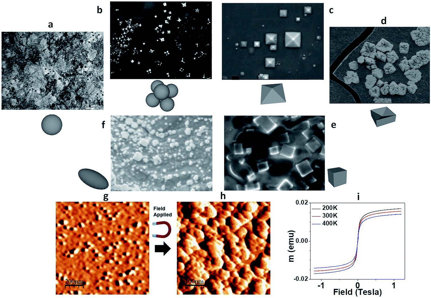 | ||
| Fig. 1 Formation and magnetic properties of MNPs. The shape transformation cycle from circular to hybrid structures of MNPs: (a) circular shapes, (b) star shapes, (c) pyramidal shapes, (d) negative pyramidal shapes, (e) square shapes, and (f) mixed states. Magnetic properties of MNPs: AFM images of MNPs (g) before and (h) after the magnetic field was applied, (i) m–H loops of MNPs using different temperature ranges. | ||
A controllable synthesis of nanocrystalline iron oxide, particularly, of the pyramidal shape of MNPs was performed. Fig. 1a–f show the transformation cycle. The initial magnetite was oxidized to the transition state before pyramid formation, and was then transformed into the square structure. After further oxidized, this structure saturates to the mixed states of the circular, square, and oval structures. It should be noted that the different oxidation levels during synthesis resulted in the coarsening of the precipitated NPs.
Bi-pyramidal structures were the most common structures as reported.31–34 However, a single pyramid is also very important, especially for magnetic sensors to focus the magnetic field along the direction of the apex. Ideally, octahedral and tetrahedral structures, indicative of the formation of self-assembled pyramidal nanodevices, can be seen in the X-ray diffraction (XRD) patterns shown in the ESI.† A unique combination of octahedral and tetrahedral lattice structures was found, resulting in perfectly shaped pyramidal pits of iron oxide MNPs.
Vibrating sample magnetometry
Vibrating sample magnetometry (VSM) shows superparamagnetic behaviour in relation to the levels of oxidation, as shown in Fig. 1c. The unique structure could be used for an intense magnetic field generation and sensing due to its unique structure. The octadecahedral α-Fe2O3 nanocrystals with a hexagonal pyramid shape were synthesised by packing truncated nanodots into several different superstructures. The findings are of fundamental importance to understanding the morphology and growth of α-Fe2O3 nanostructures. Improved control of the shape evolution of hematite particles will be studied to examine the direct correlation between exposed facets and facet controlled properties in a future study.Fe–C synthesis
For the self-aligned NPs using inkjet printing, the NPs need to be chemically stable. To avoid the oxidation state, nanocarbon coating was applied by precisely controlling the carbon states such as graphene, nanotubes, and others. The Fe–C composites were fabricated by applying a high energy milling of iron at a low temperature. The method was able to prevent oxidation and may promote Fe NPs without any oxide or impurity. It was noted that cryo-milling in an inert atmosphere had the ability to produce free NPs of metals with minimum contamination.32 The present experiments were conducted using Fe powders of 99.999% purity in a specially designed mill under pure argon.32 The curing and milling was possible at a temperature of ∼150 K with the use of liquid nitrogen (LN2) cooling.32 The average particle size was reduced substantially, because of the cryo-milling, from the approximate 20 μm size of the as-received powder to a size of ∼10 nm after 3 h of milling. Then, carbon coating was performed using chemical vapour deposition.21 Scanning electron microscopy images in Fig. 2a–d show the morphology of Fe–C structures with the changes of the growth temperature from 1000 K, 1100 K, 1200 K, to 1250 K, respectively. One of the particles was chosen for thin film energy dispersive X-ray spectroscopy analysis with a fine probe which again indicated that oxygen was absent in the NPs. Furthermore, the electron energy loss spectroscopy (EELS) did not show the presence of oxide (see the ESI† for further details). However, the analysis of EELS spectra from the edges indicates ∼0.1% of oxygen solubility in Fe.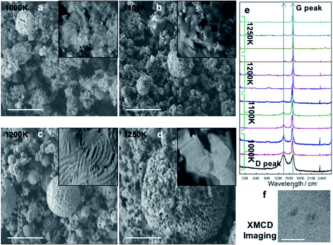 | ||
| Fig. 2 Fe–C core–shell structures. SEM images of Fe–C core–shell structures grown at 1000 K (a), 1100 K (b), 1200 K (c), and 1250 K (d) (scale bars are 1 μm). (e) Raman peaks at different synthesis temperatures and times. Notice the change of D- and G-peaks by varying the temperature ranges from 1000 K to 1250 K, respectively. (f) A full field magnetic micrograph of the Fe–C core–shell using synchrotron radiation. The dark regions represent the XMCD of the Fe–C core–shells (scale bar is 500 nm). | ||
The results of the Raman analyses showed two easily distinguished peaks which were the D- and G-peaks. From the growth temperature at 1000 K, the main peak of the Raman spectra showed both D- and G-peaks. As shown in Fig. 2e, about 60% of particles with a diameter of several hundreds of nanometers showed the presence of CNT peaks, and also mixed states of CNT and graphene at 1100 K. The graphene state was also well defined at 1200 K, but a small CNT peak was also observed. At 1250 K, an excellent graphene peak was observed and the roughness was good with tiny CNT peaks as shown in Fig. 2e.
To distinguish whether the graphene layers protected the Fe particles from oxidation, images of the MNPs were obtained using XMCD because it allowed element specific measurement. For this purpose, full-field magnetic transmission soft X-ray microscopy was used.35Fig. 2f shows the XMCD image of the Fe–C core–shell measured at the Fe-L3 absorption edge (708 eV). Fig. 2f is a differential image of two images taken at perpendicular magnetic fields of ±2700 Oe, and the dark contrast indicated that the MNPs exhibited magnetic properties of Fe, suggesting that the monolayer graphene membrane served as a coating to prevent any strong reaction as was expected.
Ink-jet printing process
Although drop casting is a well-known method to deposit MNPs onto dry substrates, it is hard to control the distribution of MNPs depending on their size because of the large volume that drops over a few μL. However, inkjet printing allowed a more precise patterning, with less volume of droplets (∼pL), from a nozzle with a diameter of tens of μm. This strategy had several advantages such as low-cost, easy access to electronic devices, and a precise material dispersion technique with non-contact deposition on a variety of substrates.27 After determining the optimal conditions, the prepared MNPs were inkjet printed onto rigid (silicon, Si) and flexible (poly(dimethylsiloxane), PDMS) substrates.The experimental details are described in the Materials and methods section. Fig. 3a shows a schematic and an optically captured image of Fe–C MNPs jetting. By optimizing the ejection conditions including voltage pulse amplitude and duration, the droplets in-flight from single nozzle were well defined spheres. Fig. 3b shows that the particles were aligned by size because of the coffee ring effect after dropping onto the substrates. The results with the deposition of Fe–C particles showed that the structures were well aligned. The size controllable effects are discussed more in detail in the ESI.† Using inkjet printing, the size and distribution of MNPs could be controlled as shown in Fig. 3c. Fig. 3d shows that the MNPs were well aligned in a uniform way. The size distribution showed that the uniform arrays of NPs having a diameter of sub 10 nm were aligned in the middle region. When they were deposited on a PDMS substrate, it was observed that the MNPs were well aligned. The left and right images of Fig. 3d show scanning electron microscopy (SEM) and atomic force microscopy (AFM) images of MNPs deposited on PDMS substrate, respectively.
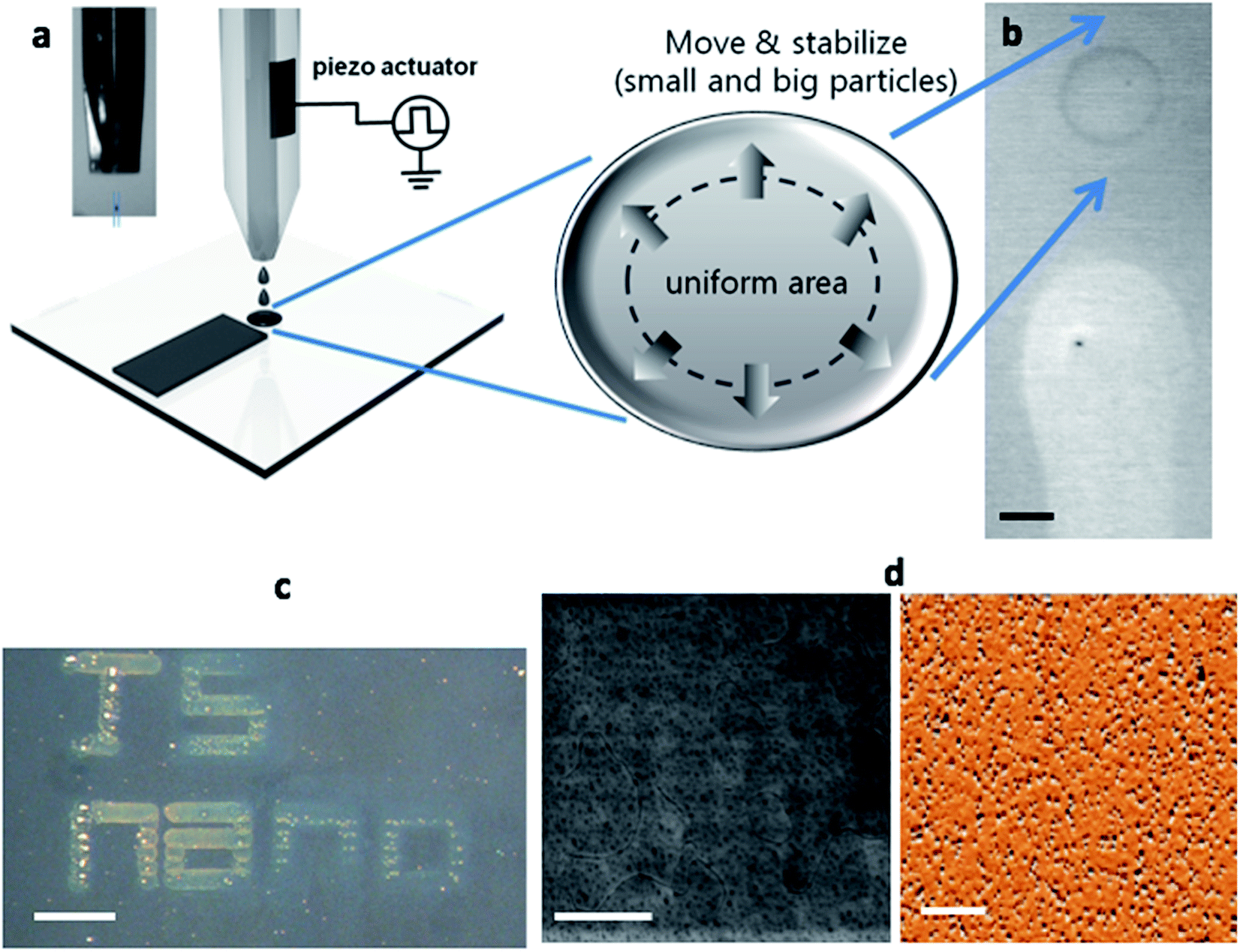 | ||
| Fig. 3 Distribution of the MNPs using inkjet printing. (a) A schematic of the inkjet jetting image which shows micro-sized Fe–C solution drops. The volume of an ejected single droplet was 60 pL from a nozzle with a diameter of 30 μm. (b) An optical microscopy image of an MNP single drop (top) and line (bottom) formation onto a Si substrate. When exploiting the coffee ring effect, the particles were aligned by a uniform size. (c) Using optimal drops and lines, drop-on demand printing was performed (Scale bar is 2 mm). (d) The resulting images of uniformly arrayed Fe–C structures onto PDMS using SEM (L) and AFM (R) (scale bar is 2 μm). | ||
Materials and methods
Nanomagnetic particle fabrication
Nanomagnetic particles were fabricated using coprecipitation from a solution of ferrous and ferric mixed salts in the ratio of 1![[thin space (1/6-em)]](https://www.rsc.org/images/entities/char_2009.gif) :2 under the ambient conditions of the bulk aqueous solution and surfactant systems.11,16,24 De-ionized water (300 mL) was deaerated in a three-necked flask by stirring with the application of ultra-high purity nitrogen. First, 2 g of hydrated ferrous chloride (FeCl2·2H2O), was mixed with 5.4 g of hydrated ferric chloride (FeCl3·6H2O), in 300 mL of water, and then dissolved at 30–40 °C. Then, a solution of 5 g sodium hydroxide in water at 50 °C was added at a constant stirring rate of 2000 rpm, and a black magnetite precipitate was deposited.
:2 under the ambient conditions of the bulk aqueous solution and surfactant systems.11,16,24 De-ionized water (300 mL) was deaerated in a three-necked flask by stirring with the application of ultra-high purity nitrogen. First, 2 g of hydrated ferrous chloride (FeCl2·2H2O), was mixed with 5.4 g of hydrated ferric chloride (FeCl3·6H2O), in 300 mL of water, and then dissolved at 30–40 °C. Then, a solution of 5 g sodium hydroxide in water at 50 °C was added at a constant stirring rate of 2000 rpm, and a black magnetite precipitate was deposited.
Transmission electron microscopy
A transmission electron microscope (TEM; Philips CM200) with an acceleration voltage of 200 kV was used to take the TEM images. A field-emission gun equipped with an imaging filter (Gatan, GIF200) running DigitalMicrograph™ (Gatan) software was used. The TEM samples were prepared by placing a drop of mini-emulsion onto a carbon-coated copper (Cu) grid under ambient conditions.X-ray diffraction
The XRD measurements were made using a powder X-ray diffractometer (Siemens, D-5000) equipped with a Cu anode operated at 40 kV and 40 mA. The XRD patterns were collected using a step size of 0.01° and a scan rate of 1 step per s. Data were analyzed from the Powder Diffraction File (PDF).Scanning electron microscopy
The SEM (Jeol 9000F) was performed at 15 kV and a working distance of 5 mm.Vibrating sample magnetometry
The m–H loop measurements were performed using the VSM option of a cryogenic physical property measurement system (PPMS, Quantum Design) with a 9 T superconducting magnet. Samples were mounted in a regular tube holder. To optimize the touchdown process, the samples were mounted with an upward offset of 35 mm. The magnetic field was swept at the rate of 15 Oe s−1.Magnetic force microscopy
The AFM (Veeco, MultiMode system) study was performed in non-contact mode. High sensitivity magnetic tunnel junction probes (2 nT Hz−1) at 50 Hz were provided by JS Nanotechnologies (San Jose, CA). The particle imaging was performed in a standard scanning probe microscopy system.XM-1 microscopy
The XMCD was carried out using full-field soft X-ray transmission microscopy at the Lawrence Berkeley National Laboratory, Advanced Light Source, Beamline 6.1.2 along the Fe (708 eV) absorption edge. For the transmission measurement, the MNPs were prepared on a transparent silicon nitride membrane.Inkjet printing
The MNPs were printed on a 60 °C substrate using a customized drop-on-demand piezoelectric-type inkjet printing system with MJ-AT-01 nozzles (MicroFab Corp). The experimental conditions were based on the following parameters: concentration, type of solvent, substrate temperature, and drop spacing. Different conditions were tried by changing the concentrations (0.1, 0.5, or 1.0 g mL−1 s−1), of different solvents such as: isopropyl alcohol or acetone. The temperature range of the substrates was 50, 60, and 70 °C. The variations of drop spacing were performed from 30 to 180 μm. Using the optimal results, MNPs were deposited onto different substrates such as rigid and flexible ones.Conclusions
Three important milestones were found for MNPs. Firstly, the formation of self-assembled 3D pyramidal NPs could be optimized by changing the process conditions. The formation of four phases of the self-assembled 3D nanodevices such as pyramidal, square, hybrid, and circular nanostructures could be controlled. Secondly, Fe–C particles could be used to prevent oxidation and showed strong XMCD images at the Fe L3 edge. That means that carbon prevents the penetration of any atoms into the Fe core. Lastly, inkjet printing was applied to align the MNPs. The MNPs were aligned in a size controllable and uniform way onto flexible substrates. These results pave the way for their use in the field of NP-based future electronics and smart medicine.Conflicts of interest
There are no conflicts to declare.Acknowledgements
This work is supported by the National Natural Science Foundation of China under Award number 61674062. The work was supported by the US Department of Energy, Office of Basic Energy Sciences, Division of Materials Sciences and Engineering under Contract No. DE-AC02-05CH11231. The Authors would like to thank JS Nanotechnologies LLC (http://www.jsnanotech.com) for their support (Contract No. JS-Nano-1901110). This work was also supported by the National Research Foundation of Korea supported by the Korean Government (Ministry of Science and ICT) #2018R1A5A6075964, #2017R1A2B2003928, and #2017M3A7B4049173. The Authors acknowledge the financial support from Air Force Office of Scientific Research (AFOSR, USA) under Award number FA9550-18-1-0527 and the National Science Foundation (NSF) under Award numbers 0939514 and 1810270.Notes and references
- G. M. Whitesides, et al.,Molecular Self-Assembly and Nanochemistry: a Chemical Strategy for the Synthesis of Nanostructures, Science, 1991, 254(5036), 1312–1319 CrossRef CAS PubMed.
- Y. Sun and Y. Xia, Shape-controlled synthesis of gold and silver nanoparticles, Science, 2002, 298(5601), 2176–2179 CrossRef CAS PubMed.
- K. L. Prime and G. M. Whitesides, Self-assembled organic monolayers: model systems for studying adsorption of proteins at surfaces, Science, 1991, 252(5009), 1164–1167 CrossRef CAS PubMed.
- C. Granqvist, R. Buhrman, J. Wyns and A. Sievers, Far-Infrared Absorption in Ultrafine Al Particles, Phys. Rev. Lett., 1976, 37(10), 625–629 CrossRef CAS.
- P. Yu, Y. Yao, J. Wu, X. Niu, A. L. Rogach and Z. Wang, Effects of Plasmonic Metal Core-Dielectric Shell Nanoparticles on the Broadband Light Absorption Enhancement in Thin Film Solar Cells, Sci. Rep., 2017, 7(1), 7696 CrossRef PubMed.
- C. A. S. Batista, R. G. Larson and N. A. Kotov, Nonadditivity of nanoparticle interactions, Science, 2015, 350(6257), 1242477 CrossRef PubMed.
- M. A. Mitchnick, D. Fairhurst and S. R. Pinnell, Microfine zinc oxide (Z-cote) as a photostable UVA/UVB sunblock agent, J. Am. Acad. Dermatol., 1999, 40(1), 85–90 CrossRef CAS PubMed.
- D. Llamosa, M. Ruano, L. Martinez, A. Mayoral, E. Roman, M. García-Hernández and Y. Huttel, The ultimate step towards a tailored engineering of core@shell and core@shell@shell nanoparticles, Nanoscale, 2014, 6, 13483–13486 RSC.
- M. E. Akerman, W. C. Chan, P. Laakkonen, S. N. Bhatia and E. Ruoslahti, Nanocrystal targeting in vivo, Proc. Natl. Acad. Sci. U. S. A., 2002, 99(20), 12617–12621 CrossRef CAS PubMed.
- A. Fu, C. M. Micheel, J. Cha, H. Chang, H. Yang and A. P. Alivisatos, Discrete nanostructures of quantum dots/Au with DNA, J. Am. Chem. Soc., 2004, 126(35), 10832–10833 CrossRef CAS PubMed.
- A.-H. Lu, E. L. Salabas and F. Schüth, Magnetic Nanoparticles: Synthesis, Protection, Functionalization, and Application, Angew. Chem., Int. Ed., 2007, 46(8), 1222–1244 CrossRef CAS PubMed.
- G. Reiss and A. Hutten, Magnetic Nanoparticles, in Handbook of Nanophysics: Nanoparticles and Quantum Dots, ed. D. K. Sattler, CRC Press, 2010, pp. 11-1–19-1 Search PubMed.
- B. Gleich and J. Weizenecker, Tomographic imaging using the nonlinear response of magnetic particles, Nature, 2005, 435(7046), 1214–1217 CrossRef CAS PubMed.
- K. E. Scarberry, E. B. Dickerson, J. F. McDonald and Z. J. Zhang, Magnetic Nanoparticle-Peptide Conjugates for in Vitro and in Vivo Targeting and Extraction of Cancer Cells", J. Am. Chem. Soc., 2008, 130(31), 10258–10262 CrossRef CAS PubMed.
- X. Meng, H. C. Seton, L. T. Lu, I. A. Prior, N. T. K. Thanh and B. Song, Magnetic CoPt nanoparticles as MRI contrast agent for transplanted neural stem cells detection, Nanoscale, 2011, 3(3), 977–984 RSC.
- S. Kralj and D. Makovec, Magnetic Assembly of Superparamagnetic Iron Oxide Nanoparticle Clusters into Nanochains and Nanobundles, ACS Nano, 2015, 9(10), 9700–9707 CrossRef CAS PubMed.
- J.-P. Wang and J. Bai, High-magnetic-moment core-shell-type FeCo–Au/AgFeCo–Au/Ag nanoparticles, Appl. Phys. Lett., 2005, 87, 152502 CrossRef.
- R. Qiao, Q. Jia, S. Hüwel, R. Xia, T. Liu, F. Gao, H.-J. Galla and M. Gao, Receptor-Mediated Delivery of Magnetic Nanoparticles across the Blood–Brain Barrier, ACS Nano, 2012, 6(4), 3304–3310 CrossRef CAS PubMed.
- M. A. Busquets, A. Espargaró, R. Sabaté and J. Estelrich, Magnetic Nanoparticles Cross the Blood-Brain Barrier: When Physics Rises to a Challenge, Nanomaterials, 2015, 5(4), 2231–2248 CrossRef CAS PubMed.
- M. Zhang, F. Xiao, X. Z. Xu and D. S. Wang, Novel ferromagnetic nanoparticle composited PACIs and their coagulation characteristics, Water Res., 2011, 46(1), 127–135 CrossRef PubMed.
- J. Hong, H. N. Hwang, A. T. N‘Diaye, J. Liang, G. Chen, Y. Park, L. T. Singh, Y. G. Jung, J. H. Yang, J. I. Jeong, A. K. Schmid, E. Arenholz, H. Yang, J. Bokor, C. C. Hwang and L. You, The interfacial spin modulation of graphene on Fe(111), 2018, ArXiv 1811.09773 Search PubMed.
- F. Yu and V. C. Yang, Size-tunable synthesis of stable superparamagnetic iron oxide nanoparticles for potential biomedical applications, J. Biomed. Mater. Res. A, 2011, 92(4), 1468–1475 Search PubMed.
- Z. Kelgenbaeva, E. Omurzak, S. Takebe, S. Sulaimankulova, Z. Abdullaeva, C. Iwamoto and T. Mashimo, Synthesis of pure iron nanoparticles at liquid-liquid interface using pulsed plasma, J. Nanoparticle Res., 2014, 16, 2603 CrossRef.
- H. K. D. Kim, L. T. Schelhas, S. Keller, J. L. Hockel, S. H. Tolbert and G. P. Carman, Magnetoelectric control of superparamagnetism, Nano Lett., 2013, 13, 884–888 CrossRef CAS PubMed.
- R. Guduru, P. Liang, C. Runowicz, M. Nair, V. Atluri and S. Khizroev, Magneto-electric Nanoparticles to enable field-controlled high-specificity drug delivery to eradicate ovarian cancer cells, Sci. Rep., 2013, 3, 2953 CrossRef PubMed.
- M. Nair, R. Guduru, P. Liang, J. Hong, V. Sagar and S. Khizroev, Externally controlled on-demand release of anti-HIV drug using magneto-electric nanoparticles as carriers, Nat. Commun., 2013, 4, 1707 CrossRef PubMed.
- S. Chung, J. Lee, H. Song, S. Kim, J. Jeong and Y. Hong, Inkjet-printed stretchable silver electrode on wave structured eleastomeric substrate, Appl. Phys. Lett., 2011, 98(15), 153110 CrossRef.
- L. T. Kuhn, A. K. Geim, J. G. S. Lok, P. Hedegard, K. Ylanen, J. B. Jensen, E. Johnson and P. E. Lindelof, Magnetisation of isolated single crystalline Fe-nanoparticles measured by a ballistic Hall micro-magnetometer, Eur. Phys. J. D, 2000, 10, 259–263 CrossRef CAS.
- A. K. Gupta and M. Gupta, Synthesis and surface engineering of iron oxide nanoparticles for biomedical applications, Biomaterials, 2005, 26(18), 3995–4021 CrossRef CAS PubMed.
- A. Lassoued, B. Dkhil, A. Gadri and S. Ammar, Control of the shape and size of iron oxide (alpha-Fe2O3) nanoparticles synthesized through the chemical precipitation method, Results Phys., 2017, 7, 3007–3015 CrossRef.
- C. S. Tiwary, S. Kashyap, K. Biswas and K. Chattopadhyay, Synthesis of pure iron magnetic nanoparticles in large quantity, J. Phys. D: Appl. Phys., 2013, 46(38), 385001 CrossRef.
- S. Hosseinzadeh, A. Yazdani and R. Khordad, Pure iron nanoparticles prepared by electric arc discharge method in ethylene glycol, Eur. Phys. J. Appl. Phys., 2012, 59(3), 30401 CrossRef.
- M. Lin, L. Tng, T. Lim, M. Choo, J. Zhang, H. R. Tan and S. Bai, Hydrothermal synthesis of octadecahedral Hematitie (alpha-Fe2O3) nanoparticles: an expitaxial growth from goethite (alpha-FeOOH), J. Phys. Chem. C, 2014, 118, 10903–10910 CrossRef CAS.
- X.-F. Qu, G.-T. Zhou, Q.-Z. Yao and S.-Q. Fu, Aspartic-acid-assisted hydrothermal growth and properties of magnetite octahedrons, J. Phys. Chem. C, 2010, 114, 284–289 CrossRef CAS.
- S.-G. Je, M.-S. Jung, M.-Y. Im and J.-I. Hong, Electric current control of creation and annihilation of sub-100-nm magnetic bubbles examined by full-field transmission soft X-ray microscopy, Curr. Appl. Phys., 2018, 18(11), 1201–1204 CrossRef.
Footnote |
| † Electronic supplementary information (ESI) available. See DOI: 10.1039/c9na00146h |
| This journal is © The Royal Society of Chemistry 2019 |