Inorganic sulfide solid electrolytes for all-solid-state lithium secondary batteries
Peng-Jie
Lian
a,
Bo-Sheng
Zhao
a,
Lian-Qi
Zhang
*b,
Ning
Xu
c,
Meng-Tao
Wu
c and
Xue-Ping
Gao
 *a
*a
aInstitute of New Energy Material Chemistry, School of Materials Science and Engineering, Nankai University, Tianjin 300350, China. E-mail: xpgao@nankai.edu.cn; Fax: +86-22-23500876; Tel: +86-22-23500876
bSchool of Materials Science and Engineering, Tianjin University of Technology, Tianjin 300384, China. E-mail: lianqizhang@126.com
cTianjin Bamo Tech Co., Ltd., Tianjin 300384, China
First published on 22nd August 2019
Abstract
Liquid organic electrolytes are mostly used in commercial lithium-ion batteries, due to their advantages of high conductivity and excellent wetting of the electrode interface. However, liquid organic electrolytes are flammable and volatile, causing safety issues of commercial lithium-ion batteries in electric vehicles. Recently, all-solid-state lithium secondary batteries have attracted great attention owing to their high safety and increased energy density, and are considered the most promising next generation energy storage systems. The most essential components are solid electrolytes for all-solid-state lithium batteries. Among various inorganic solid electrolytes, sulfide solid electrolytes have received widespread attention because of their high ionic conductivity and good mechanical properties. Herein, we summarize the development of several typical sulfide solid electrolytes and the problems to be addressed in emerging all-solid-state lithium batteries. Finally, the future development directions of sulfide electrolytes and all-solid-state lithium batteries are briefly discussed.
1 Introduction
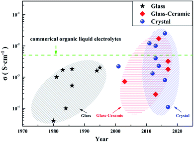
With the rapid development of new energy technologies, the demand for secondary battery systems with high energy density and high safety has become increasingly urgent. According to a worldwide technical goal, the energy density of secondary batteries needs to reach 500 W h kg−1 in 2030. However, current lithium-ion batteries (LIBs) can hardly achieve this target.1–3 Commercial LIBs mostly employ liquid organic electrolytes, which show flammable and volatile features compared to the solid electrolytes (SEs) with high safety.4,5 Compared to traditional LIBs with liquid electrolytes, all-solid-state lithium secondary batteries using SEs theoretically have the following features: (1) higher safety due to the mechanical prevention of leaking and burning of SEs; (2) bi-function of SEs as separators and electrolytes in all-solid-state batteries; (3) better mechanical strength for ensuring long-term operation, compared with traditional polymer separators; (4) fewer side reactions between SEs and electrodes; (5) wider electrochemical window of SEs, as compared with liquid organic electrolytes; (6) high lithium ion migration number close to 1 in SEs. However, there are still great challenges for all-solid-state lithium secondary batteries compared to LIBs with liquid electrolytes: (1) poor wettability for solid electrolytes, resulting in poor contact between SEs and active materials compared to liquid electrolytes; (2) unstable rigid interface between SEs and active materials due to the volume expansion and contraction of active materials during cycling, which can damage or terminate the battery; (3) unsuccessful commercialization SEs for all-solid-state batteries based on considerations of high conductivity, high stability and low cost.SEs can be classified into two main groups: inorganic solid electrolytes and polymer solid electrolytes. Polymer solid electrolytes with good mechanical properties are helpful in improving the battery safety performance during production and operation. However, polymer solid electrolytes are still unsatisfactory, due to their low conductivity, narrow electrochemical window, and poor stability at elevated temperatures.6–8 The inorganic solid electrolytes, also known as lithium fast ion conductors, can be mainly classified into two types: oxide solid electrolytes (hereinafter referred to as O-SEs) and sulfide solid electrolytes (hereinafter referred to as S-SEs). There are many types of O-SEs: natrium superionic conductors (NASICON), perovskites, garnets, γ-Li3PO4, and some amorphous oxides, including Li2O–MOx (M = Si, B, and P) and LiPON-related materials.9–13 The O-SEs have good electrochemical stability and thermal stability, but relatively low conductivity (10−7 to 10−4 S cm−1 at room temperature) and rigid mechanical property, limiting their commercial application in battery systems.14–16 The S-SEs are mainly composed of Li2S and sulfides (such as SiS2, P2S5, and GeS2). Compared with O-SEs, the electronegativity of S2− in S-SEs is less than that of O2−, so the binding of lithium ions is weak and more free lithium ions migrate inside S-SEs. In addition, the radius of S2− is larger than that of O2−, which is favourable for forming a large transmission channel of lithium ions. Therefore, S-SEs usually have higher lithium ion conductivity (10−5 to 10−2 S cm−1 at room temperature, Fig. 1) compared with O-SEs. Furthermore, S-SEs have better ductility than O-SEs, which is favourable for good contact between the electrode materials and S-SEs by simple cold pressing, as well as convenient for the manufacture of bulk all-solid-state batteries.17,18 In this review, we summarize the development, intrinsic features, and applications of S-SEs in all-solid-state lithium secondary batteries. The emerging challenges and trends in all-solid-state lithium secondary batteries are also discussed.
2 Sulfide solid electrolytes
2.1 Lithium ion transport mechanism of S-SEs
S-SEs initially originated from Pradel's research on Li2S–SiS2 in 1986.19 There are three ways of sulfur accumulation in SEs: body-centred cubic (BCC) stacking, face-centred cubic (FCC) stacking, and hexagonal close packing (HCP). In BCC stacking (for example, Li7P3S11 and Li10GeP2S12), Li-ions migrate along the path connecting the two coplanar tetrahedral sites (T1 and T2, Fig. 2a) with a very low barrier of 0.15 eV, called the T–T path. In FCC stacking (like Li2S), Li-ions move from a tetrahedral site (T1) to another tetrahedral site (T2) through an intermediate octahedral site (O1), which is called the T–O–T path, with a barrier of 0.39 eV (Fig. 2b). The T–O–T path can also be found in the a–b plane of the HCP lattice (T1 to T2 through O1 in Fig. 2c) with almost the same activation barrier (0.40 eV). The migration of Li-ions along the c-axis in the HCP lattice is the T–T path through two face-sharing tetrahedral sites (T1 and T3, Fig. 2c) with a low barrier of 0.20 eV. Li-ions can also migrate across the path connecting two coplanar octahedral sites (O1 and O2, 0.19 eV, Fig. 2c) along the c-axis. However, the O–O path needs additional activation energy due to the instability of octahedral positions. Therefore, migration of Li-ions in the HCP lattice is likely to occur by an alternation of T–T and T–O–T paths. Therefore, the activation barrier of the lithium ion migration pathway in the body-centered-cubic anion framework is lower than that of other close-packed frameworks,15 which is beneficial to achieve high ionic conductivity.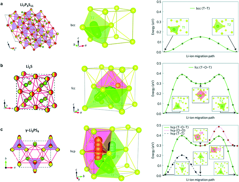 | ||
| Fig. 2 (a–c) Crystal structures of the Li-ion conductors (a) Li7P3S11, (b) Li2S and (c) γ-Li3PS4. The Li ions, partially occupied Li+ sites, S2− anion, and PS4 tetrahedral and GeS4 tetrahedral sites (partially occupied in Li10GeP2S12) are coloured green, green-white, yellow, purple and blue, respectively. In both Li10GeP2S12 and Li7P3S11, the sulfur anion sublattice can be closely mapped to a bcc framework (red circles connected by red lines). In Li2S, the anion sublattice is an exact fcc matrix (yellow-red circles). The anion sublattices in γ-Li3PS4 and Li4GeS4 closely match to a hcp framework. Reprinted with permission.15 Copyright© 2015, Springer Nature. | ||
2.2 Crystalline state of S-SEs
According to their crystalline state, S-SEs can be divided into three categories: glass, glass-ceramic and crystal. Glassy electrolytes have attracted much attention due to their isotropic ion conduction, zero grain boundary resistance and low cost.20 The ionic conductivity of glassy electrolytes can reach about 10−4 S cm−1 at room temperature.21–24 Meanwhile, the glass-ceramic electrolytes obtained by crystallization from glassy electrolytes have higher conductivity, about 10−3 S cm−1 (even up to 10−2 S cm−1), at room temperature.25–29 This is because the glassy electrolyte softens and reduces the grain boundary resistance during the crystallization process. In addition, the precipitation of partial crystallites also helps improve the lithium ion conductivity. The crystal electrolytes will be mentioned in the next section.There are three main methods for preparing S-SEs: melt quenching, mechanical milling, and wet chemistry. Table 1 shows a comparison of the three preparation methods. Considering feasibility and safety, most S-SEs are prepared by mechanical milling. This work mainly classifies the electrolytes based on their crystalline structure. According to their structures, S-SEs can be divided into the following two categories: thio-lithium super ion conductors (thio-LiSICONs) and argyrodite type.
| Method | Advantage | Disadvantage |
|---|---|---|
| Melt quenching | Low equipment requirements | High temperature |
| Easy to prepare bulk materials | Unsafe | |
| Suitable for preparing glass, glass-ceramic and crystal SEs | Complicated operation | |
| Mechanical milling | Simple operation | Long working hours |
| High safety | ||
| Easy to prepare powder materials | ||
| Suitable for preparing glass, glass-ceramic and crystal SEs | ||
| Wet chemistry | Controllable morphology | Residual organic waste |
| Easy to prepare powder materials | Strict preparation conditions | |
| Suitable for crystal SEs |
| Composition | State | Ionic conductivity (S cm−1) | Activation energy (eV) | Ref. |
|---|---|---|---|---|
| 50Li2S–50GeS2 | Glass | 4 × 10⁻⁵ | 0.51 | 31 |
| 60Li2S–40SiS2 | Glass | 5.3 × 10⁻⁴ | 0.33 | 19 |
| 67Li2S–33P2S5 | Glass | 10−4 | 0.36 | 32 |
| Li7P3S11 | Glass-ceramic | 3.2 × 10⁻³ | 0.125 | 26 |
| Li7P3S11 | Glass-ceramic | 1.7 × 10⁻² | 0.18 | 21 |
| Li3PS4 | Glass-ceramic | 2.8 × 10⁻⁴ | 0.356 | 33 and 34 |
| 78Li2S–22P2S5 | Glass-ceramic | 1.78 × 10⁻³ | 0.31 | 35 |
| 80Li2S–20P2S5 | Glass-ceramic | 7.2 × 10⁻⁴ | 0.25 | 33 |
| Li7Ge3PS12 | Crystal | 1.1 × 10⁻⁴ | 0.26 | 36 |
| Li3.25Ge0.25P0.75S4 | Crystal | 2.2 × 10⁻³ | 0.207 | 30 |
| Li9.54Si1.74P1.44S11.7Cl0.3 | Crystal | 2.5 × 10⁻² | 0.238 | 37 |
| Li10GeP2S12 | Crystal | 1.2 × 10⁻² | 0.21 | 38 |
| Li10SnP2S12 | Crystal | 4 × 10⁻³ | 0.87 | 39 |
| Li10SiP2S12 | Crystal | 2.3 × 10⁻³ | 0.20 | 40 |
| Li11AlP2S12 | Crystal | 8 × 10⁻⁴ | 0.263 | 41 |
| Li6PS5Cl | Crystal | 1.3 × 10⁻³ | 0.33 | 42 |
| Li6PS5Br | Crystal | 10−2 | 0.20 | 43 |
2.2.1.1 Binary systems of Li2S–MSn. Li2S–B2S3 and Li2S–SiS2 were reported as the earlier binary systems of Li2S–MSn. However, their ion conductivity is still unsatisfactory, although the conductivity can be improved to a certain extent by doping LixMOy (M = Si, Ge, P).44 As the optimized binary system of Li2S–MSn, the Li2S–P2S5 system has good physical and chemical properties and is widely used in all-solid-state batteries. In particular, Li2S–P2S5 has a high ionic conductivity of 0.1 to 1 × 10⁻³ S cm−1 at room temperature25–29 and a wide electrochemical window.
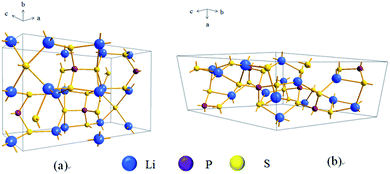
There are two typical compounds with high ionic conductivity in the binary system of Li2S–P2S5: Li3PS4 (75% Li2S–25% P2S5 molar ratio) and Li7P3S11 (70% Li2S–30% P2S5 molar ratio). Li3PS4 was first discovered in 1984 (ref. 45) and is considered the most stable compound in the binary system of Li2S–P2S5.46 Usually, Li3PS4 exists as γ-Li3PS4 with a conductivity of 3 × 10⁻⁷ S cm−1 at room temperature. When heated to 195 °C, γ-Li3PS4 is converted to β-Li3PS4 with a conductivity of 9 × 10⁻⁷ S cm−1.47 The crystalline structure of β-Li3PS4 is shown in Fig. 3a, where the PS4 and LiS4 tetrahedra are dominant. There have been many effective attempts for improving the conductivity of β-Li3PS4 in the past. After preparation by mechanical ball milling and subsequent heat treatment at 230 °C, Li3PS4 presents a high conductivity of 2.8 × 10⁻⁴ S cm−1 at room temperature.33 A special β-Li3PS4 with nanopores (about 100 nm), prepared by wet chemistry, shows a conductivity of 1.6 × 10⁻⁴ S cm−1 at room temperature, which is nearly 3 orders of magnitude higher than that of crystalline Li3PS4. Meanwhile, the nanoporous Li3PS4 exhibits good compatibility with lithium and has a wide electrochemical window of 5 V.34 A plate-like Li3PS4 (about 3 μm in length, 500 nm in width, and 100–200 nm in thickness), prepared by liquid-phase shaking, presents a conductivity as high as 2.0 × 10⁻⁴ S cm−1 at room temperature.48
In general, Li7P3S11 is obtained in the 70% Li2S–30% P2S5 composition and is an extremely important member of the binary system due to its very high ionic conductivity (up to 1.7 × 10⁻² S cm−1 at RT).21,49 Some types of fast ion conductors are derived from the original Li7P3S11 structure. Usually, Li7P3S11 is unstable at high temperatures. When the temperature is increased to 420 °C, Li7P3S11 decomposes into two fast ion conductors: β-Li3PS4 and Li4P2S7.50 In Fig. 3b, Li7P3S11 is shown as a triclinic structure consisting of PS4 tetrahedra and P2S7 double tetrahedra, where Li-ions are located in the polyhedral cavity.26 Different preparation methods are reported for the Li7P3S11 structure. Li7P3S11 obtained by mechanical ball milling and subsequent heat-treatment at 280 °C shows a high conductivity of 3.2 × 10⁻³ S cm−1 at room temperature and low activation energy.51 Afterward, the conductivity of Li7P3S11 can be gradually increased by optimizing the preparation method. The optimized Li7P3S11 prepared by hot pressing has a high conductivity of 1.7 × 10⁻² S cm−1 at room temperature, almost equivalent to that of liquid organic electrolytes.21 The low grain boundary resistance during the heat treatment could be the main reason for the high conductivity of the optimized Li7P3S11. Another important example for preparing Li7P3S11 is the wet chemistry method by a two-step reaction: (1) the formation of solid Li3PS4·ACN phase and amorphous “Li2S–P2S5” phase in liquid phase and (2) the subsequent conversion between the two phases. The conductivity of the as-prepared Li7P3S11 sample reaches as high as 8.7 × 10⁻⁴ S cm−1 at room temperature.52
Although positive and effective progress has been made to enhance the conductivity of Li2S–P2S5 binary systems, some problems still remain at present: (1) poor chemical stability: S-SEs are extremely sensitive to moisture and easily react with steam in the air to produce toxic H2S gas and destroy the structure of sulfides.17 (2) The cost of S-SEs with Li2S as raw material is high. (3) Compatibility between S-SEs and the cathode materials of lithium secondary batteries is poor, which will be further discussed in a following section. Therefore, regulating the components of S-SEs by introducing oxides and phosphate is an effective way to increase the chemical stability. For example, Li2O–Li2S–P2S5 prepared by replacing partial Li2S with Li2O could effectively inhibit the generation of H2S gas.53 70% Li2S–29% P2S5–1% Li3PO4 system, after doping Li3PO4 into 70% Li2S–30% P2S5, shows a high conductivity of 1.87 × 10⁻³ S cm−1 at room temperature and enhanced chemical stability.27 As for cost, seeking new raw materials or exploring new preparation methods could be fundamental solutions.
2.2.1.2 Li2S–P2S5–MeS2 ternary system. Recently, typical thio-LiSICON structure Li10GeP2S12 (abbreviated as LGPS afterward) was developed, with an extremely high conductivity of 1.2 × 10⁻² S cm−1 at 27 °C, which is comparable to or higher than those of the liquid organic electrolytes currently used in commercial Li-ion batteries.38 As indicated in Fig. 4a, LGPS consists of (Ge0.5P0.5)S4 tetrahedra, PS4 tetrahedra, LiS4 tetrahedra and LiS6 octahedra. (Ge0.5P0.5)S4 and LiS6 form a 1D chain along the c-axis by sharing a common edge. These 1D chains are connected to each other by the PS4 tetrahedra, which are connected to the LiS6 octahedra through a shared angle. Fig. 4b shows the 1D conduction pathways of Li-ions along the c-axis in superionic conductors. Indeed, the addition of Ge element in Li2S–P2S5 system could greatly improve the conductivity. However, at the same time, the stability of LGPS against metal lithium is reduced due to the oxidation property of Ge4+. This means that the interfacial stability against metal lithium is still limited for LGPS.28
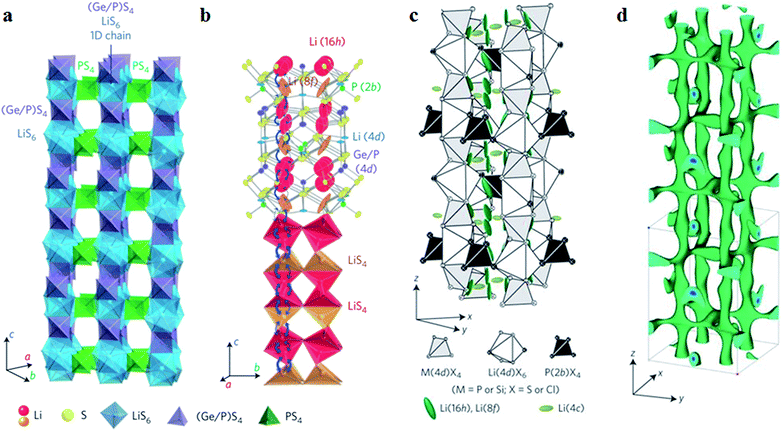 | ||
| Fig. 4 (a) Framework structure of LGPS; (b) Li+ conduction pathways in LGPS; (c) crystal structure of Li9.54Si1.74P1.44S11.7Cl0.3; (d) nuclear distributions of Li atoms in Li9.54Si1.74P1.44S11.7Cl0.3 at 25 °C. Reproduced with permission.37,38 Copyright© (2011, 2016), Springer Nature. | ||
Of course, the cost factor is important for wide application of S-SEs in batteries and the price of Ge element is still high.54 From theoretical calculations, the isovalent cation substitution of Ge4+ has minor impact on the intrinsic properties of LGPS.55 Therefore, the replacement of Ge with tetravalent cations may reduce the cost of S-SEs. Here, Li10SiP2S12 and Li10SnP2S12 have similar structure, electrochemical stability and Li-ion conductivity to LGPS. After replacing Ge4+ with Sn4+, Li10SnP2S12 shows a high conductivity of 4 × 10⁻³ S cm−1 at room temperature and the cost is only one-third that of the Li2S–GeS2–P2S5 system.39 The Ge can be also replaced with Si by high pressure method and the obtained Li11Si2PS12 shows a high conductivity of 2.3 × 10⁻³ S cm−1 at room temperature.56 Multi-components could be a good strategy for manipulating the conductivity of S-SEs. In particular, halogen elements in the multi-components are demonstrated to be effective for improving the conductivity. For example, the multi-component Li9.54Si1.74P1.44S11.7Cl0.3 with a remarkably high conductivity of 2.5 × 10⁻² S cm−1 at 25 °C was reported, which was the highest value so far for thio-LiSICONs.37 It was demonstrated from the anisotropic thermal displacement of lithium (Fig. 4c) and nuclear density distribution (Fig. 4d) that three-dimensional (3D) conduction pathways of Li ions (1D along the c-axis and 2D in the a–b plane) can be formed in Li9.54Si1.74P1.44S11.7Cl0.3, superior to the unique 1D pathway of the LGPS family. Therefore, the formation of widely distributed 3D conduction pathways in Li9.54Si1.74P1.44S11.7Cl0.3 may contribute to its highest ionic conductivity at room temperature.
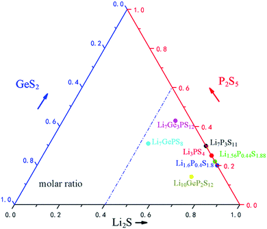
The distribution of commonly used ternary S-SEs in the Li2S–GeS2–P2S5 ternary phase diagram is illustrated in Fig. 5. Clearly, the Li2S is dominant in the commonly used sulfide electrolytes (≥50% molar ratio); lower P2S5 and GeS2 contents are used here to manipulate the crystallographic structure and intrinsic features. Among all the S-SEs, thio-LiSICONs are the most promising electrolytes for all-solid-state lithium secondary batteries, due to their unique structures and high ionic conductivity at room temperature. Although the conductivity of thio-LiSICONs is comparable to or even higher than those of organic liquid electrolytes, their chemical stability and compatibility with cathode materials are still unsatisfactory, which could undermine the practical application of S-SEs in all-solid-state batteries and urgently needs to be solved.
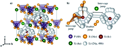 | ||
| Fig. 6 (a) Crystal structures of Li6PS5X with X = Cl, Br, and I. (b) Lithium ion transport mechanism. Reproduced with permission.72 Copyright© 2017, American Chemical Society. | ||
Argyrodite type solid electrolytes are very promising for all-solid-state batteries based on the considerations of conductivity and cost. However, similar to most S-SEs, the argyrodite type solid electrolytes are very sensitive to moisture, which should be the main focus for future applications.
To sum up, a wide variety of S-SEs with high conductivities has been reported, with thermal evolution of ionic conductivity drawn in Fig. 7. Here, high conductivity (higher than 10−3 S cm−1 at room temperature) is a primary concern for solid electrolytes to be used in all-solid-state lithium secondary batteries. It can be seen that there are only a few electrolyte systems that can meet the demand of high conductivity: Li9.54Si1.74P1.44S11.7Cl0.3, Li10GeP2S12, doped-Li3N, Li3.25GeP0.75S4, Li2S–SiS2–Li3PO4, Li14Zn(GeO4)4, and Li7P3S11. Among all the electrolytes, Li14Zn(GeO4)4 is stable, but not ideal due to its excessive hardness and poor compatibility with electrode materials. For the doped-Li3N sample, ion conductivity is satisfactory, but the low decomposition voltage and extreme sensitivity toward moisture are insurmountable at present. The applications of obtained Li9.54Si1.74P1.44S11.7Cl0.3, Li3.25GeP0.75S4 and Li2S–SiS2–Li3PO4 are largely limited due to their hard preparation processes and complex elemental components. It seems that every family of these electrolytes has problems currently. Comparatively speaking, Li10GeP2S12 and Li7P3S11 are the most promising solid electrolytes for high performance all-solid-state lithium secondary batteries due to their high conductivities and simple preparation process. Of course, there is still great room for improvement of conductivity in solid electrolytes, so it is necessary to explore new electrolyte systems based on the requirement of high conductivity.
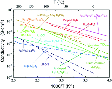 | ||
| Fig. 7 Thermal evolution of ionic conductivity for different types of solid electrolytes. Reprinted with permission.81 Copyright© 2018, Royal Society of Chemistry. | ||
3 S-SE's application in all-solid-state lithium batteries
With constant progress in highly conductive solid electrolytes, the developments in all-solid-state lithium secondary batteries change rapidly. The schematic structures of three commonly used lithium batteries with solid electrolytes are shown in Fig. 8.82 The first advantage of all-solid-state batteries is high safety, due to their simplified structure and the excellent mechanical properties of solid electrolytes. Another outstanding advantage of all-solid-state lithium batteries is their high theoretical energy density.83–85 The energy density of all-solid-state lithium batteries could reach 300–600 W h kg−1, which is much higher than commercial liquid batteries at about 200 W h kg−1.85–88 The reasons are as follows: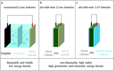 | ||
| Fig. 8 Comparison of (a) commercial Li-ion batteries, (b) all-solid-state Li-ion batteries and (c) all-solid-state Li–S batteries. | ||
(1) Lithium has the lowest electrode potential and the lowest molar mass and its theoretical specific capacity can reach 3860 mA h g−1.89,90 The compatibility of the S-SEs with lithium is better than that of liquid electrolytes with lithium, because of fewer side reactions on the interface. Therefore, lithium can be used as the anode in all-solid-state batteries, which is helpful to increase the volumetric and gravimetric energy densities of all-solid-state batteries.
(2) Solid electrolytes usually have a wide electrochemical window. When combined with suitable cathode materials, the battery could provide a high operation voltage to improve the energy density.38,87,88
Although the ionic conductivity of S-SEs is competitive to those of liquid electrolytes, the electrochemical performance of all-solid-state lithium batteries is still unsatisfactory, highly depending on the interface issues between electrodes and S-SEs.91 There are several key issues of S-SE application in all-solid-state lithium batteries: (1) A solid–solid contact interface is formed between the electrode and electrolyte, but is not stable enough; (2) the volume change of the electrode during charge and discharge is unavoidable, which further destroys the electrode/electrolyte interface; (3) the chemical stability of S-SEs is poor. It was mentioned above that the chemical stability can be effectively improved to a certain extent by manipulating the composition of the electrolytes and optimizing the preparation process. However, the issue of solid–solid interfaces between electrodes and electrolytes is unavoidable in all-solid-state batteries92 and should be paid more attention.
3.1 Interface layer and interface impedance
In all-solid-state lithium batteries, the interface between the electrolytes and electrodes has significant influence on the working mechanism and electrochemical performance.93–97 In particular, no wettability exists among solids; the contact between solid and solid is not comparable with that of solid and liquid, leading to large interfacial impedance between solid electrolytes and electrodes. The space charge layer model, proposed by Takada et al., is popular to explain the interfacial impedance between the S-SEs and oxide cathode materials in all-solid-state lithium batteries.98 Another explanation for the interface phenomenon is mutual diffusion of different elements in oxide electrodes and S-SEs.993.2 Problems and current situation of the interface between oxide cathodes and sulfide solid electrolytes
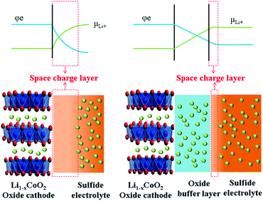
The concept of a space charge layer was initially proposed based on a pioneering work on solid-state reactions, where the interface between two F− ion conductors of BaF2 and CaF2 was studied. It was demonstrated that partial F− ions can be transferred from one side to the other to reach equilibrium state under the driving force of different chemical potentials, resulting in the formation of vacancies and interstitial ions. Both the vacancies and interstitial ions help enhance ion conduction at the interface. This phenomenon was referred to as “nanoionics”.100,101Takada et al. introduced the nanoionic phenomenon into the interface between oxide electrodes and S-SEs, forming a space-charge layer.91 The space-charge layer on the interface between oxide cathodes and S-SEs is harmful for cation transfer. This is a common feature of good ionic conductivity for both cathode materials and S-SEs. However, the electron insulation is absolute for S-SEs, while the good electron conductivity is also suitable for cathode materials. Currently, commercial cathode materials with large capacity are generally Ni-rich oxides with high electrode potentials. When contacting both oxide cathode materials and S-SEs, Li-ions move from S-SEs to the oxide under the driving force of chemical potential difference between the two materials. Correspondingly, the migration of Li-ions results in formation of the space-charge layer on the interface between S-SEs and oxide cathode. Specifically, the composition and structure of S-SEs on the interface are changed, leading to lower ion conductivity and increasing the interfacial resistance. However, the space charge layer on the cathode side of the oxide interface disappears rapidly because electrons simultaneously neutralize excess Li-ions. Therefore, the space charge layer is usually formed in the S-SE side on the interface between cathode and S-SE (as shown in Fig. 9).98 The formation of the space charge layer has great impact on the performance of all-solid-state lithium batteries.
Thus, to improve the electrochemical performance of all-solid-state lithium batteries, reducing the impact of the space charge layer is imperative. Takada proposed a buffer layer to alleviate development of the space charge layer.84 Inserting an additional oxide layer as an ion-conductive and electron-insulated buffer layer between the oxide cathode and S-SEs is an effective way to slow the impact of the space charge layer.91,102 Correspondingly, two interfaces are formed after introducing the buffer layer: one between the mixed-conducting oxide cathode and ion-conductive oxide and the other between the ion-conductive oxide and S-SEs. The space charge layer at both interfaces could be inhibited to a certain extent. The additional oxide layer avoids direct contact between oxide cathode and S-SEs as a buffer, so it is called a buffer layer. Take LiCoO2 and S-SEs as examples, as shown in Fig. 9. The space charge layer is largely developed when S-SEs are in direct contact with the LiCoO2. With a buffer layer between LiCoO2 and S-SEs, the space charge layer is greatly suppressed.
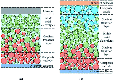
Therefore, it is important to search for suitable buffer layer materials to improve the performance of all-solid-state batteries. Electrodes in all-solid-state lithium batteries are usually mixtures of active materials, conductive additives and S-SEs. Here, the buffer layer should be formed on the surface of active materials before mixture. The current investigation shows that the mass ratio of Li10GeP2S12 and LiCoO2 in the composite cathodes is usually between 20/80 and 30/70 for better electrochemical performance.92 In the future, the content of S-SEs as inactive materials in the electrode should be manipulated as low as possible to maintain the high energy density of all-solid-state lithium batteries. For effective transport of ions and conduction of electrons, the interface between electrodes and S-SEs could be constructed as a gradient. This special gradient transition layer would help stabilize the interface and improve the performance of all-solid-state lithium batteries. Fig. 10 shows more details about the interface structure and gradient transition layer for all-solid-state lithium batteries, as well as the composite cathode, Li anode and S-SEs.
Next, the interfacial problems between S-SEs and oxide cathodes will be discussed for different oxide cathodes in all-solid-state lithium batteries.
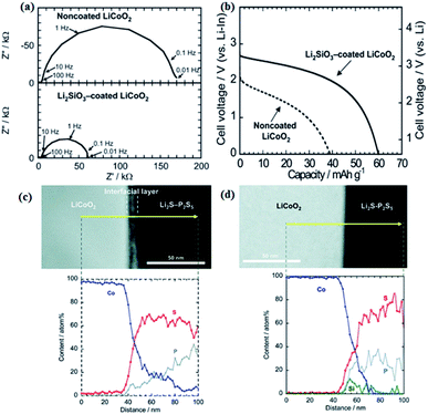 | ||
| Fig. 11 (a) Impedance profiles of the all-solid-state cells In/Li2S–P2S5 with solid electrolyte non-coated and Li2SiO3-coated LiCoO2 at −30 °C after charging to 3.6 V vs. Li–In. (b) Discharge curves of the all-solid state cells under the current density of 0.064 mA cm−2 at 30 °C. (c) Cross-sectional HAADF-STEM image of LiCoO2 electrode/Li2S–P2S5 solid electrolyte interface after initial charging and cross-sectional EDX line profiles for Co, P, and S elements. (d) Cross-sectional HAADF-STEM image of the Li2SiO3-coated LiCoO2/Li2S–P2S5 interface after initial charging and cross-sectional EDX line profiles for Co, P, S, and Si elements.99,108 Reproduced with permission. Copyright© (2009, 2010), American Chemical Society. | ||
In a similar way, S-SEs can be coated onto active materials to form a favourable electrode–electrolyte interface and increase the electrochemically active surface area.109 As shown in Fig. 12, S-SEs-coated LiCoO2 exhibits larger discharge capacity and better rate performance compared to a simple mixture of LiCoO2 and S-SEs. The effects of different grain size and composition of active materials on the electrochemical performance of all-solid-state batteries are also explored. In particular, the composition of 10![[thin space (1/6-em)]](https://www.rsc.org/images/entities/char_2009.gif) :
:![[thin space (1/6-em)]](https://www.rsc.org/images/entities/char_2009.gif) 1 weight ratio of 10 μm to 1.7 μm LiCoO2 helps to show better performance, for which the solid–solid contact/interface should be optimized.
1 weight ratio of 10 μm to 1.7 μm LiCoO2 helps to show better performance, for which the solid–solid contact/interface should be optimized.
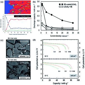 | ||
| Fig. 12 (a) Volume fractions of respective materials along the electrode thickness; (b) electrochemical performance of S-SE-coated LiCoO2 and LiCoO2 + S-SE; (c) S-SE-coated LiCoO2 particles with different grain sizes; (d) electrochemical performances of different cathode compositions. Reproduced with permission.109 Copyright© 2017, Royal Society of Chemistry. | ||
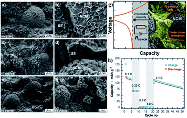 | ||
| Fig. 13 (a and b) Scanning electron micrographs of the cathode composite of NCM811 and β-Li3PS4 as prepared in a solid-state cell but without the application of current or potential. (c and d) SEMs of a Li–In|β-Li3PS4|NCM-811 batteries after single charging to 4.3 V vs. Li/Li+ at 0.1 C. (e and f) SEMs of a given cell after 50 full battery cycles in the discharged state. (g) Schematic diagram of performance degradation mechanism in all-solid-state batteries. (h) Rate test and long-term cyclability for the all-solid-state batteries. Reproduced with permission.116 Copyright© 2017, American Chemical Society. | ||
The nickel-rich oxide LiNi0.8Co0.15Al0.05O2 (NCA) cathode is also verified in all-solid-state batteries. As shown in Fig. 14, after coating a thin layer of Li2O–ZrO2 (8 nm),121 all-solid-state batteries with Li2O–ZrO2-coated NCA as cathode, 80Li2S–20P2S5 as electrolyte, and In–Li alloy as anode can be charged/discharged repeatedly with good capacity retention. The NCA can be also coated with Li4Ti5O12 (LTO) for verification in all-solid-state batteries.122 The battery with Li4Ti5O12-coated NCA cathode shows a discharge capacity of about 110 mA h g−1, superior to that (70 mA h g−1) of the non-coated cathode.
 | ||
| Fig. 14 (a) TEM image of a cross section of a 0.5 mol% LZO coated NCA particle. The right hand (dark) side corresponds to NCA; (b) cycle characteristics of bare and 0.5 mol% LZO coated NCA at 25 °C. Reproduced with permission.121 Copyright© 2013, Elsevier B.V. | ||
The effects of the particle size and structure defects of oxide cathodes in all-solid-state batteries are also important. First, reducing the particle size of the cathode materials by ball milling is helpful to form sufficient contact between the electrolytes and cathode.123,124 Secondly, a subsequent heat treatment on the ball-milled cathode materials can further reduce structural defects on the surface of the cathode materials. Thereby, the electrochemical performance of the all-solid-state battery can be improved to some extent. Typically, all-solid-state batteries with NCA, ball-milled NCA, and heat-treated NCA as cathodes are built. The interface impedances are 652, 480 and 198 Ω cm−2 and the initial discharge capacities of the cathodes are 46.7, 89 and 146 mA h g−1, respectively.
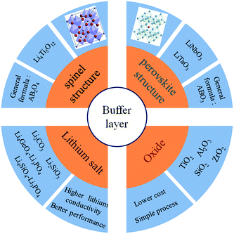
In all-solid-state lithium ion batteries, the interface compatibility between the oxide cathode materials and S-SEs should be a key issue. It is imperative to probe the reaction mechanism of the interface and find a strategy for stabilizing the interface. The commonly used buffer layer materials are summarized in the following categories according to their structure and composition (Fig. 15): spinel oxides, perovskite oxides, lithium salts, and general oxides. At first, the commonly used buffer materials have been general oxides. Although the development of the space charge layer can be suppressed to a certain extent, the rate performance of the battery is undermined due to the insulating properties of the oxide buffer layer. Compared with general oxides, lithium salts have good ion-conducting properties, leading to better rate performance of all-solid-state batteries. According to the above classification, typical examples of the three types are Li4Ti5O12, Li3PO4 and LiNbO3. A certain amount of Li4Ti5O12 coating on the cathode surface could effectively suppress the formation of the space charge layer.125 But due to its low ionic conductivity (10−9 S cm−1), the resistance of the coating layer itself became predominant in the electrode resistance, thus limiting the electrochemical performance of all-solid-state batteries. Li3PO4 has a higher ionic conductivity of 10−8 S cm−1; thus, a Li3PO4 buffer layer could lead to better performance.126 LiNbO3 is an excellent material for the buffer layer in place of Li4Ti5O12 and Li3PO4 because of its extremely high ionic conductivity of 10−5 to 10−6 S cm−1 in amorphous state and its good stability.102 It effectively reduces interfacial resistance and improves the high-rate capability of all-solid-state batteries. For buffer layer materials, high ionic conductivity, good chemical stability and electrochemical passivation feature should be considered, as well as low cost and insensitivity to moisture. Of course, LiNbO3 seems to be effective as a buffer layer for all the oxide cathode materials in all-solid-state lithium ion batteries.
4 S-SE application in all-solid-state lithium–sulfur battery
4.1 Lithium–sulfur battery
Sulfur is a light-weight element which can react with lithium to form Li2S through a two-electron reaction, leading to the high theoretical specific capacity of 1672 mA h g−1,127–131 which is about five times that of current commercial transition metal oxide cathode materials.132–137 However, there are several major problems in conventional liquid lithium–sulfur (Li–S) battery: (1) poor ionic conductivity and electrical conductivity of sulfur and its discharge product Li2S; (2) large volume expansion (∼79%) from S to Li2S; (3) dissolution of intermediate polysulfide, resulting in a shuttle effect and poor cycle performance; (4) flooded organic electrolyte, leading to low energy density; (5) flammability and leakage of the organic electrolyte. In order to improve the electrochemical performance, energy density, and safety, it is effective to build all-solid-state Li–S batteries. S-SEs could be good candidates for an all-solid-state Li–S battery. In particular, there is good compatibility between S-SEs and sulfur, without the space charge layer effect mentioned in the previous section.4.2 Research progress on all-solid-state lithium–sulfur battery
Although solid electrolytes can effectively suppress the shuttle effect of soluble intermediate polysulfide, there are still some problems with all-solid-state Li–S battery. First, due to the immobile nature of the solid electrolyte, the volume expansion caused by sulfur in the charge and discharge processes induces great stress at the electrode/electrolyte interface, damaging the structure of the interface. Second, the electron conductivities of S and Li2S are extremely poor, severely limiting the electrochemical performance of the all-solid-state Li–S battery. Third, the contacts among S/Li2S, conductive additives and solid electrolytes are insufficient. Therefore, it is urgent to search for suitable materials or modified methods to solve these problems in the all-solid-state Li–S battery.Building nanocrystals and nanostructures is an effective way to improve the above problems.138 First, the nanostructure has a large specific surface, so sufficient contact between the active materials and solid electrolytes can be formed based on the large surface. Second, although the poor conductivity of S and Li2S limits the depth of the electrochemical reaction, nanocrystals with many active sites can improve the utilization of sulphur active material. In the meantime, the nanostructure can accommodate the pressure introduced during repeated cycling.
Sulfur–AB composite cathodes prepared by ball-milling were used to build all-solid-state batteries.145 The all-solid-state battery, assembled with a sulfur–AB composite cathode, can deliver a large capacity of 996 mA h g−1 at 0.64 mA cm−2 and retain a capacity of 853 mA h g−1 at 1.3 mA cm−2 after 200 cycles. After further optimization with small particle size and sufficient contact between S and AB,146 the sulfur–AB composite cathode shows a large initial discharge capacity of 1087 mA h g−1 with a coulombic efficiency of 97% and maintains a reversible capacity of 1050 mA h g−1 at 0.064 mA cm−2 after 50 cycles. In addition, the composite cathodes using VGCF144 and AC147 as conductive additives also exhibit better electrochemical performance. Similar to carbon materials, metal sulfides (such as CuS2)139 and conductive polymers (such as polyacrylonitrile)148 are also commonly used to construct composite cathodes.
As mentioned above, constructing a composite cathode with conductive additive, solid electrolytes and Li2S is a good solution to improve the performance of Li2S. The optimal preparation process of the composite cathode with Li2S, AB and S-SEs is explored by mechanical ball milling.138 As indicated in Fig. 16, the Li2S–AB–S-SEs composite cathode can be prepared by ball milling, which is superior for capacity and cycle stability compared with manual grinding. Specifically, the Li2S–AB–S-SEs cathode has a discharge platform of 2 V (vs. Li), which corresponds to the reaction of Li2S = S + 2Li+ + 2e, proving the generation of polysulfide is suppressed. The initial charge and discharge capacities of the all-solid-state batteries with the Li2S–AB–S-SEs composite cathode are 1010 and 920 mA h g−1, respectively. To increase the utilization of the Li2S active material, the effects of the particle size of Li2S active materials on the reversible capacity and rate performance of all-solid-state batteries are also investigated. Clearly, reducing the particle size of Li2S active materials is helpful to improve the electrochemical performance of all-solid-state Li–S batteries.
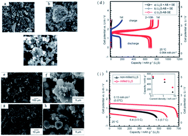 | ||
| Fig. 16 SEM images of (a) Li2S + AB + S-SEs, (b) Li2S–AB + S-SEs, and (c) Li2S–AB–S-SEs electrodes. (d) Charge–discharge curves of all-solid-state cells Li–In/80Li2S–20P2S5 glass-ceramic/Li2S using Li2S + AB + S-SEs, Li2S − AB + S-SEs, and Li2S–AB–SEs as cathodes. SEM images of (e) non-milled Li2S, (f) Li2S particles milled for 20 h, and Li2S–AB–S-SEs electrodes using (g) non-milled Li2S and (h) milled-Li2S. (i) Charge–discharge curves for the first cycle of all-solid-state cells with Li2S–AB–S-SEs electrodes prepared using (e) non-milled and (f) milled Li2S particles. Reproduced with permission.138 Copyright© 2012, Royal Society of Chemistry. | ||
It is also feasible to improve the performance of Li2S by designing a special structure. A core–shell structure with nano-Li2S as the core and Li3PS4 as the shell is obtained and has an ionic conductivity of 10−7 S cm−1 at 25 °C, almost 6 orders of magnitude higher than that of bulk Li2S (∼10−13 S cm−1).151 As demonstrated in Fig. 17, the all-solid-state battery assembled with the LSS cathode shows an initial discharge capacity of 848 mA h g−1 (based on Li2S) and a capacity retention of about 70% after 100 cycles. The good performance of LSS is ascribed to its enhanced ionic conductivity after coating with Li3PS4 and reduced interfacial resistance between the electrodes and electrolytes. The high lithium-ion conductivity of LSS results in excellent cycling performance for the all-solid-state Li–S battery, also promoting safety during cycling.
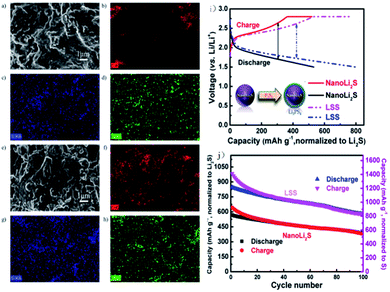 | ||
| Fig. 17 SEM images and elemental maps of the cathode before and after cycling at 60 °C: SEM images of the cathode (a) before cycling and (e) after 100 cycles; (b), (c), and (d) are elemental maps of carbon, sulfur, and phosphorus before cycling; (f), (g), and (h) are elemental maps of carbon, sulfur, and phosphorus after 100 cycles. (i) The schematic diagram of the core–shell structure and voltage–capacity curve of the battery. (j) Electrochemical cycling performance of nano-Li2S and LSS as the cathode materials for all-solid-state Li–S batteries at the rate of C/10 and 60 °C. Reproduced with permission.151 Copyright© 2013, American Chemical Society. | ||
In summary, the insulation of S/Li2S is the main problem hindering the development of the all-solid-state Li–S battery. Intimate contact among electrode components is effective to reduce the particle size and improve the conductivity of composite electrodes to solve the above problems.
In order to achieve intimate contact between sulfide electrodes and S-SEs, Fe3S4@Li7P3S11 is prepared by in situ coating Li7P3S11 on Fe3S4.155 The Fe3S4@Li7P3S11 nanocomposites are employed to construct all-solid-state batteries. The all-solid-state batteries (Li/75% Li2S–24% P2S5–1% P2O5/Li10GeP2S12/Fe3S4@Li7P3S11) show superior cycling stability. As shown in Fig. 18, after 200 cycles, the discharge capacity remained a high value of 1001 mA h g−1 at a current density of 0.1 A g−1. Subsequently, sulfide nickel anchored carbon nanotube (NiS–CNT) nanocomposites are prepared by a facile hydrothermal method.3 The all-solid-state batteries with NiS–CNT as cathode also deliver high reversible capacity and excellent cycling stability.
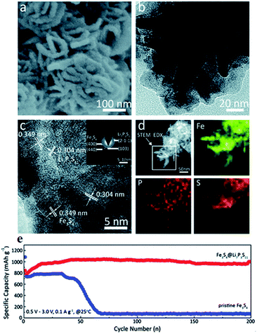 | ||
| Fig. 18 (a) High magnification SEM, (b) TEM, and (c) HRTEM images of Fe3S4@Li7P3S11 nanocomposites; the inset in (c) is the SAED pattern; (d) STEM-EDS elemental mapping images of Fe3S4@Li7P3S11 nanocomposites, marked by the rectangular region, for Fe, P, and S. (e) Comparison of the electrochemical performance between Fe3S4@Li7P3S11 and pristine Fe3S4. Reproduced with permission. Copyright© 2017.155 Royal Society of Chemistry. | ||
5 Current situation of the interface between anode/S-SEs
5.1 Characteristics of metal lithium
Metal lithium is an ideal anode material due to its low standard electrode potential (−3.04 V vs. standard hydrogen electrode), low density (0.53 g cm−1) and high theoretical specific capacity of 3862 mA h g−1.89 Conventional lithium batteries with organic liquid electrolytes have poor compatibility with metal lithium. Metal lithium is extremely reactive and easily forms uncontrolled lithium dendrites at the anode surface, thus leading to internal short-circuiting and serious safety issues.97,156,157 In all-solid-state lithium batteries, all components are solid. The solid electrolyte has good mechanical properties which can weaken the growth of lithium dendrites during charge/discharge cycling. Therefore, metal lithium can be employed as an anode in all-solid-state lithium batteries with high energy density. Although S-SEs have good mechanical properties, they are electrochemically unstable to metal lithium.158 It implies that the interface change between the anode and S-SEs could be serious and strongly related to the performance of all-solid-state batteries. This part will discuss the interfacial problem from two aspects: electrochemical stability and mechanical stability.5.2 Electrochemical stability of the interface between metal lithium and S-SEs
In fact, most highly-conductive S-SEs (such as Li7P3S11, Li10GeP2S12, and Li9.54Si1.74P1.44S11.7Cl0.3) are unstable against active lithium metal.37,113,159 To improve electrochemical stability between S-SEs and lithium and to reduce the decomposition of S-SEs, lithium alloys are introduced as anodes.160,161 Among all the alloys, Li–In alloy with a flat potential platform of 0.62 V (vs. Li/Li+) and a high specific capacity is widely used in all-solid-state lithium batteries to suppress interfacial reactions and the decomposition of solid state electrolytes.160 Of course, the energy density of all-solid-state batteries can be slightly reduced due to low battery voltage with Li–In alloy as anode. In addition, cost should be a concern for a battery with indium as anode material. Therefore, improving the interfacial stability between the lithium metal and S-SEs to inhibit the growth of Li dendrites is critical for utilization of S-SEs in all-solid-state lithium secondary batteries.The electrochemical stability can be improved by doping anions into S-SEs. Li7P2S8I, prepared by doping LiI in Li3PS4, shows extremely high electrochemical stability to a metal lithium anode.162 Improving the interface between lithium metal anode and S-SEs could be done through the following three aspects: (1) modification on the surface of S-SEs; (2) modification on the surface of metal lithium; (3) introduction of a buffer layer between S-SEs and metal lithium.35 Among these, the buffer layer solution is the most commonly used. Therefore, the characteristics of different buffer layer materials are explored. 20 nm Si-deposited metal lithium is obtained by laser pulse deposition163 and the LiCoO2|Li2S–P2S5|Li battery is then assembled. Here, the battery with bare lithium anode presents a capacity retention rate of 76% after 100 cycles, while the battery with Si-deposited lithium anode is cycled without capacity decay almost for 1000 cycles. Subsequently, different deposited layers of Si, Al and Sn on the surface of metal lithium are studied.163 The all-solid-state batteries with Si-deposited lithium anode exhibit optimized electrochemical performance. Employing LiF (or LiI) as a buffer layer at the interface between metal Li and S-SEs and penetrating methoxyperfluorobutane (HFE) or I solution inside S-SEs could effectively suppress Li dendrite growth (Fig. 19).164 A LiCoO2@LiNbO3/Li7P3S11/Li all-solid-state battery employing HFE-penetrated Li7P3S11 glass-ceramic as electrolyte and LiF-coated Li metal as anode shows a high reversible discharge capacity of 118.9 mA h g−1 at 0.1 mA cm−2 and retains 96.8 mA h g−1 after 100 cycles.
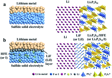 | ||
| Fig. 19 Schematic diagrams of (a) Li/Li7P3S11 interface of ASSLIBs and (b) modified interface with a uniform thin LiF (or LiI) interphase layer and HFE (or I solution) infiltrated sulfide electrolyte. Reprinted with permission.164 Copyright© 2018, Elsevier B.V. | ||
5.3 Mechanical stability of the interface between metal lithium and S-SEs
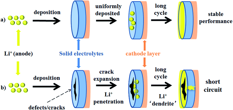
Another important problem is the formation of Li dendrites along the voids and grain boundaries in solid electrolytes, although these materials have much stronger mechanical strength than Li metals.157 In fact, there are problems similar to lithium dendrite growth in solid electrolytes. The mechanism for dendrite formation and growth in solid electrolytes is still unclear and controversial.Metal lithium reacts and grows along grain boundaries and cracks inside the S-SEs.157 However, lithium dendrites are still formed and grown in the glassy sulfide electrolytes without a grain boundary.165 In order to suppress the growth of Li dendrites, it is necessary to prevent the interfacial reaction between the solid electrolyte and Li. Therefore, it is necessary to understand the mechanical parameters of sulfide solid electrolytes to analyse interface problems. The Young's modulus, hardness, and fracture toughness of glassy 70Li2S–30P2S5 solid electrolytes were determined to be 18.5 ± 0.9 GPa, 1.9 ± 0.2 GPa, and 0.23 ± 0.04 MPa m1/2, respectively.166 As illustrated in Fig. 20, L2S–P2S5-type electrolytes are more compliant and brittle than crystalline oxide electrolytes. The low stiffness of the glassy electrolytes indicates that the electrolytes can accommodate mismatch in interfacial stress in all-solid-state batteries. But their ability is easily affected by low fracture toughness and cycling-generated flaws.
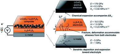 | ||
| Fig. 20 Summary of mechanical performance data for Li2S–P2S5 (LPS) in the context of all-solid-state batteries. Reprinted with permission.166 Copyright© 2017, John Wiley and Sons. | ||
Monroe and Newman propose that solid electrolytes with sufficiently high shear modulus (about twice that of Li, which has shear modulus of 4.2 GPa)167 could suppress the formation of Li dendrites.168,169 However, this theory cannot explain the phenomenon that appeared in Porz et al.'s work.165 There is still a disturbance by metal lithium dendrite growth in glassy Li2S–P2S5 with a shear modulus of 8.3 GPa. The growth mechanism of lithium dendrites in four types of solid electrolytes, glassy Li2S–P2S5, β-Li3PS4, and polycrystalline and single crystal LLZTO, is studied by galvanostatic electrodeposition experiments combined with in situ and ex situ microscopy. As shown in Fig. 21a, a model is proposed to explain the effect of stress accumulation on lithium dendrite growth. An electrochemomechanical model for growth of lithium-filled cracks is developed. Fig. 21b shows the relationship between the minimum over-potential and the defect size for glassy Li2S–P2S5 and LLZTO. The relationship between maximum stress and defect size is also plotted. When studying the mechanism of lithium metal penetration through glassy Li2S–P2S5, lithium metal is uniformly deposited in the region of the glassy Li2S–P2S5 with no crack and gradually propagates laterally from the electrode contact point as shown in Fig. 22a. However, when lithium metal is deposited near the precracked area, cracks are formed and extended into the sample, causing structural damage and even short-circuit as the experiment progressed, as in Fig. 22b. It is concluded that stabilization of the interfaces between solid electrolytes and lithium metal will require minimizing interface defects. The factors governing lithium penetration through brittle electrolytes are investigated by performing lithium electrodeposition on single-crystal Li6La3ZrTaO12 garnets.170 It is concluded that the risk of lithium metal penetration can be reduced by designing the battery with a larger cathode, smaller anode and small thickness/width ratio.
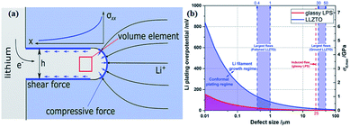 | ||
| Fig. 21 (a) The effect of stress accumulation on lithium growth; (b) inverse square root dependence of Li plating over-potential and crack-extension stress (σ0,max) on defect size of glassy LPS and LLZTO. Reproduced with permission.165 Copyright© 2017, John Wiley and Sons. | ||
6 Conclusions and prospects
All-solid-state batteries are the most promising energy storage system for next generation applications, due to their good safety, high energy density and wide operating temperature. Among all the solid electrolytes, S-SEs have received extensive attention owing to their high conductivity, wide electrochemical window, and good mechanical properties. However, there are still great challenges for the application of S-SEs in all-solid-state batteries: (1) S-SEs are extremely sensitive to moisture and easily react with water in the air to produce toxic H2S gas and therefore destroy the structure of the electrolyte; (2) problems of the interface between electrode/electrolyte still need to be settled.This work mainly reviews the research progress of S-SEs and their applications in all-solid-state lithium and all-solid-state Li–S batteries. The future development of emerging all-solid-state batteries should focus on the following aspects: (1) exploring new types of S-SEs or new preparation methods to improve the conductivity of Li-ions to meet practical applications; (2) enhancing the chemical and thermal stabilities of sulfide electrolytes; (3) improving the interface between the solid electrolytes and the electrodes; (4) optimizing the preparation process of all-solid-state batteries.
As the most promising energy storage system, there is still a long way to go in realizing the commercialization of all-solid-state batteries based on the requirements of safety, energy density and cycle stability.
Conflicts of interest
There are no conflicts to declare.Acknowledgements
Financial supports from Science and Technology Support Plan of Tianjin (19YFZCGX00220), and Natural Science Foundation (21875123, and 21421001) of China are gratefully acknowledged.Notes and references
- J. B. Goodenough and K. S. Park, J. Am. Chem. Soc., 2013, 135, 1167–1176 CrossRef CAS.
- L. Fan, H. L. Zhuang, L. Gao, Y. Lu and L. A. Archer, J. Mater. Chem. A, 2017, 5, 3483–3492 RSC.
- Q. Zhang, G. Peng, J. P. Mwizerwa, H. Wan, L. Cai, X. Xu and X. Yao, J. Mater. Chem. A, 2018, 6, 12098–12105 RSC.
- J. B. Goodenough, J. Solid State Electrochem., 2012, 16, 2019–2029 CrossRef CAS.
- K. Xu, Chem. Rev., 2014, 114, 11503–11618 CrossRef CAS.
- Z. Stoeva, I. Martin-Litas, E. Staunton, Y. G. Andreev and P. G. Bruce, J. Am. Chem. Soc., 2003, 125, 4619–4626 CrossRef CAS.
- Q. Pan, D. M. Smith, H. Qi, S. Wang and C. Y. Li, Adv. Mater., 2015, 27, 5995–6001 CrossRef CAS PubMed.
- C. Yuan, J. Li, P. Han, Y. Lai, Z. Zhang and J. Liu, J. Power Sources, 2013, 240, 653–658 CrossRef CAS.
- R. Jalem, M. Nakayama and T. Kasuga, Solid State Ionics, 2014, 262, 589–592 CrossRef CAS.
- Y. Harada, T. Ishigaki, H. Kawai and J. Kuwano, Solid State Ionics, 1998, 108, 407–413 CrossRef CAS.
- H. Xu, S. Wang, H. Wilson, F. Zhao and A. Manthiram, Chem. Mater., 2017, 29, 7206–7212 CrossRef CAS.
- R. Murugan, V. Thangadurai and W. Weppner, Angew. Chem., Int. Ed., 2007, 46, 7778–7781 CrossRef CAS.
- V. Thangadurai and W. Weppner, Ionics, 2006, 12, 81–92 CrossRef CAS.
- J. L. Fourquet, H. Duroy and M. P. Crosnier-Lopez, J. Solid State Chem., 1996, 127, 283–294 CrossRef CAS.
- Y. Wang, W. D. Richards, S. P. Ong, L. J. Miara, J. C. Kim, Y. Mo and G. Ceder, Nat. Mater., 2015, 14, 1026–1032 CrossRef CAS PubMed.
- A. Mei, X. Wang, Y. Feng, S. Zhao, G. Li, H. Geng, Y. Lin and C. Nan, Solid State Ionics, 2008, 179, 2255–2259 CrossRef CAS.
- A. Hayashi, K. Noi, A. Sakuda and M. Tatsumisago, Nat. Commun., 2012, 3, 856–860 CrossRef PubMed.
- A. Hayashi, A. Sakuda and M. Tatsumisago, Front. Energy Res., 2016, 4, 1–13 Search PubMed.
- J. H. Kennedy and Y. Yang, J. Electrochem. Soc., 1986, 133, 2437–24378 CrossRef CAS.
- C. Cao, Z.-B. Li, X.-L. Wang, X.-B. Zhao and W.-Q. Han, Front. Energy Res., 2014, 2, 1–10 Search PubMed.
- Y. Seino, T. Ota, K. Takada, A. Hayashi and M. Tatsumisago, Energy Environ. Sci., 2014, 7, 627–631 RSC.
- Z. Liu, Y. Tang, X. Lü, G. Ren and F. Huang, Ceram. Int., 2014, 40, 15497–15501 CrossRef CAS.
- Y. Seino, K. Takada, B.-C. Kim, L. Zhang, N. Ohta, H. Wada, M. Osada and T. Sasaki, Solid State Ionics, 2005, 176, 2389–2393 CrossRef CAS.
- T. Inada, K. Takada, A. Kajiyama, M. Kouguchi, H. Sasaki, S. Kondo, M. Watanabe, M. Murayama and R. Kanno, Solid State Ionics, 2003, 158, 275–280 CrossRef CAS.
- M. Eom, S. Choi, S. Son, L. Choi, C. Park and D. Shin, J. Power Sources, 2016, 331, 26–31 CrossRef CAS.
- H. Yamane, M. Shibata, Y. Shimane, T. Junke, Y. Seino, S. Adams, K. Minami, A. Hayashi and M. Tatsumisago, Solid State Ionics, 2007, 178, 1163–1167 CrossRef CAS.
- B. Huang, X. Yao, Z. Huang, Y. Guan, Y. Jin and X. Xu, J. Power Sources, 2015, 284, 206–211 CrossRef CAS.
- M. Kotobuki and M. Koishi, Ceram. Int., 2013, 39, 4645–4649 CrossRef CAS.
- M. Tatsumisago, M. Nagao and A. Hayashi, J. Asian Ceram. Soc., 2018, 1, 17–25 CrossRef.
- R. Kanno and M. Murayama, J. Electrochem. Soc., 2001, 148, A742–A746 CrossRef CAS.
- M. Ribes, B. Barrau and J. Souquet, J. Non-Cryst. Solids, 1980, 38, 271–276 CrossRef.
- R. Mercier, J.-P. Malugani, B. Fahys and G. Robert, Solid State Ionics, 1981, 5, 663–666 CrossRef CAS.
- A. Hayashi, S. Hama, T. Minami and M. Tatsumisago, Electrochem. Commun., 2003, 5, 111–114 CrossRef CAS.
- Z. Liu, W. Fu, E. A. Payzant, X. Yu, Z. Wu, N. J. Dudney, J. Kiggans, K. Hong, A. J. Rondinone and C. Liang, J. Am. Chem. Soc., 2013, 135, 975–978 CrossRef CAS PubMed.
- Y. Zhang, R. Chen, T. Liu, Y. Shen, Y. Lin and C. W. Nan, ACS Appl. Mater. Interfaces, 2017, 9, 28542–28548 CrossRef CAS PubMed.
- Y. Inoue, K. Suzuki, N. Matsui, M. Hirayama and R. Kanno, J. Solid State Chem., 2017, 246, 334–340 CrossRef CAS.
- Y. Kato, S. Hori, T. Saito, K. Suzuki, M. Hirayama, A. Mitsui, M. Yonemura, H. Iba and R. Kanno, Nat. Energy, 2016, 1, 1–7 Search PubMed.
- N. Kamaya, K. Homma, Y. Yamakawa, M. Hirayama, R. Kanno, M. Yonemura, T. Kamiyama, Y. Kato, S. Hama, K. Kawamoto and A. Mitsui, Nat. Mater., 2011, 10, 682–686 CrossRef CAS PubMed.
- P. Bron, S. Johansson, K. Zick, J. Schmedt auf der Gunne, S. Dehnen and B. Roling, J. Am. Chem. Soc., 2013, 135, 15694–15697 CrossRef CAS PubMed.
- J. M. Whiteley, J. H. Woo, E. Hu, K.-W. Nam and S.-H. Lee, J. Electrochem. Soc., 2014, 161, A1812–A1817 CrossRef.
- P. Zhou, J. Wang, F. Cheng, F. Li and J. Chen, Chem. Commun., 2016, 52, 6091–6094 RSC.
- S. Boulineau, M. Courty, J.-M. Tarascon and V. Viallet, Solid State Ionics, 2012, 221, 1–5 CrossRef CAS.
- V. Epp, Ö. Gün, H.-J. Deiseroth and M. Wilkening, J. Phys. Chem. Lett., 2013, 4, 2118–2123 CrossRef CAS.
- A. Hayashi, H. Yamashita, M. Tatsumisago and T. Minami, Solid State Ionics, 2002, 148, 381–389 CrossRef CAS.
- J. P. Malugani, R. Mercier and M. Tachez, Solid State Ionics, 1986, 21, 131–138 CrossRef CAS.
- H. Muramatsu, A. Hayashi, T. Ohtomo, S. Hama and M. Tatsumisago, Solid State Ionics, 2011, 182, 116–119 CrossRef CAS.
- K. Homma, M. Yonemura, T. Kobayashi, M. Nagao, M. Hirayama and R. Kanno, Solid State Ionics, 2011, 182, 53–58 CrossRef CAS.
- N. H. H. Phuc, K. Morikawa, T. Mitsuhiro, H. Muto and A. Matsuda, Ionics, 2017, 23, 2061–2067 CrossRef.
- K. Minami, A. Hayashi and M. Tatsumisago, J. Am. Ceram. Soc., 2011, 94, 1779–1783 CrossRef CAS.
- F. Mizuno, A. Hayashi, K. Tadanaga and M. Tatsumisago, Adv. Mater., 2005, 17, 918–921 CrossRef CAS.
- F. Mizuno, A. Hayashi, K. Tadanaga and M. Tatsumisago, Solid State Ionics, 2006, 177, 2721–2725 CrossRef CAS.
- Y. Wang, D. Lu, M. Bowden, P. Z. El Khoury, K. S. Han, Z. D. Deng, J. Xiao, J.-G. Zhang and J. Liu, Chem. Mater., 2018, 30, 990–997 CrossRef CAS.
- T. Ohtomo, A. Hayashi, M. Tatsumisago and K. Kawamoto, J. Solid State Electrochem., 2013, 17, 2551–2557 CrossRef CAS.
- Y. Mo, S. P. Ong and G. Ceder, Chem. Mater., 2011, 24, 15–17 CrossRef.
- S. P. Ong, Y. Mo, W. D. Richards, L. Miara, H. S. Lee and G. Ceder, Energy Environ. Sci., 2013, 6, 148–156 RSC.
- A. Kuhn, O. Gerbig, C. Zhu, F. Falkenberg, J. Maier and B. V. Lotsch, Phys. Chem. Chem. Phys., 2014, 16, 14669–14674 RSC.
- W. F. Kuhs, R. Nitsch and K. Scheunemann, Acta Crystallogr., Sect. B: Struct. Crystallogr. Cryst. Chem., 1978, 34, 64–70 CrossRef.
- S. Geller, Z. Kristallogr., 1979, 149, 31 CAS.
- B. Krebs and J. Mandt, Z. Naturforsch., B: Anorg. Chem., Org. Chem., 1977, 32, 373 Search PubMed.
- W. F. Kuhs, R. Nitsch and K. Scheunemann, Mater. Res. Bull., 1979, 14, 241–248 CrossRef CAS.
- E. E. Hellstrom and R. A. Huggins, J. Solid State Chem., 1980, 35, 207–214 CrossRef CAS.
- F. Boucher, M. Evain and R. Brec, J. Solid State Chem., 1993, 107, 332–346 CrossRef CAS.
- H. Wada, M. Ishii, M. Onoda, M. Tansho and A. Sato, Solid State Ionics, 1996, 86, 159–163 CrossRef.
- M. Evain, E. Gaudin, F. Boucher, V. Petricek and F. Taulelle, Acta Crystallogr., Sect. B: Struct. Sci., 1998, 54, 376–383 CrossRef.
- E. Gaudin, F. Boucher, V. Petricek, F. Taulelle and M. Evain, Acta Crystallogr., Sect. B: Struct. Sci., 2000, 56, 402–408 CrossRef.
- R. Belin, L. Aldon, A. Zerouale, C. Belin and M. Ribes, Solid State Sci., 2001, 3, 251–265 CrossRef CAS.
- E. Gaudin, H. J. Deiseroth and T. Zaiß, Z. Kristallogr., 2001, 216, 39–44 CAS.
- H.-J. Deiseroth, J. Maier, K. Weichert, V. Nickel, S.-T. Kong and C. Reiner, Z. Anorg. Allg. Chem., 2011, 637, 1287–1294 CrossRef CAS.
- N. J. J. de Klerk, I. Rosłoń and M. Wagemaker, Chem. Mater., 2016, 28, 7955–7963 CrossRef CAS.
- H. M. Chen, C. Maohua and S. Adams, Phys. Chem. Chem. Phys., 2015, 17, 16494–16506 RSC.
- H. J. Deiseroth, S. T. Kong, H. Eckert, J. Vannahme, C. Reiner, T. Zaiss and M. Schlosser, Angew. Chem., Int. Ed., 2008, 47, 755–758 CrossRef CAS.
- M. A. Kraft, S. P. Culver, M. Calderon, F. Bocher, T. Krauskopf, A. Senyshyn, C. Dietrich, A. Zevalkink, J. Janek and W. G. Zeier, J. Am. Chem. Soc., 2017, 139, 10909–10918 CrossRef CAS.
- R. P. Rao and S. Adams, Phys. Status Solidi A, 2011, 208, 1804–1807 CrossRef CAS.
- R. R. Prasada, N. Sharma, V. K. Peterson and S. Adams, Solid State Ionics, 2013, 230, 72–76 CrossRef.
- P. R. Rayavarapu, N. Sharma, V. K. Peterson and S. Adams, J. Solid State Chem., 2011, 16, 1807–1813 Search PubMed.
- M. Chen, R. P. Rao and S. Adams, Solid State Ionics, 2014, 262, 183–187 CrossRef CAS.
- M. Chen and S. Adams, J. Solid State Electrochem., 2014, 19, 697–702 CrossRef.
- M. Chen, R. Prasada Rao and S. Adams, Solid State Ionics, 2014, 268, 300–304 CrossRef CAS.
- M. Chen, X. Yin, M. V. Reddy and S. Adams, J. Mater. Chem. A, 2015, 3, 10698–10702 RSC.
- Z. Zhang, L. Zhang, Y. Liu, C. Yu, X. Yan, B. Xu and L.-m. Wang, J. Alloys Compd., 2018, 747, 227–235 CrossRef CAS.
- Z. Zhang, Y. Shao, B. Lotsch, Y.-S. Hu, H. Li, J. r. Janek, L. F. Nazar, C.-W. Nan, J. Maier, M. Armand and L. Chen, Energy Environ. Sci., 2018, 11, 1945–1976 RSC.
- B. D. McCloskey, J. Phys. Chem. Lett., 2015, 6, 4581–4588 CrossRef CAS PubMed.
- Y. Kato, K. Kawamoto, R. Kanno and M. Hirayama, Electrochemistry, 2012, 80, 749–751 CrossRef CAS.
- Z. Zhang, Y. Shao, B. Lotsch, Y. S. Hu, H. Li, J. Janek, L. F. Nazar, C. W. Nan, J. Maier, M. Armand and L. Chen, Energy Environ. Sci., 2018, 11, 1945–1976 RSC.
- X. Judez, G. G. Eshetu, C. Li, L. M. Rodriguez-Martinez, H. Zhang and M. Armand, Joule, 2018, 2, 2208–2224 CrossRef CAS.
- A. Manthiram, X. Yu and S. Wang, Nat. Rev. Mater., 2017, 2, 16103 CrossRef CAS.
- J. Haruyama, K. Sodeyama, L. Han, K. Takada and Y. Tateyama, Chem. Mater., 2014, 26, 4248–4255 CrossRef CAS.
- J. W. Fergus, J. Power Sources, 2010, 195, 4554–4569 CrossRef CAS.
- D. Aurbach, J. Electrochem. Soc., 1996, 143, 3525 CrossRef CAS.
- W. Xu, J. Wang, F. Ding, X. Chen, E. Nasybulin, Y. Zhang and J.-G. Zhang, Energy Environ. Sci., 2014, 7, 513–537 RSC.
- N. Ohta, K. Takada, L. Zhang, R. Ma, M. Osada and T. Sasaki, Adv. Mater., 2006, 18, 2226–2229 CrossRef CAS.
- W. Zhang, D. A. Weber, H. Weigand, T. Arlt, I. Manke, D. Schroder, R. Koerver, T. Leichtweiss, P. Hartmann, W. G. Zeier and J. Janek, ACS Appl. Mater. Interfaces, 2017, 9, 17835–17845 CrossRef CAS PubMed.
- Y. Tian, T. Shi, W. D. Richards, J. Li, J. C. Kim, S.-H. Bo and G. Ceder, Energy Environ. Sci., 2017, 10, 1150–1166 RSC.
- B. Wu, S. Wang, W. J. Evans IV, D. Z. Deng, J. Yang and J. Xiao, J. Mater. Chem. A, 2016, 4, 15266–15280 RSC.
- N. J. J. de Klerk and M. Wagemaker, ACS Appl. Energy Mater., 2018, 1, 5609–5618 CAS.
- L. Xu, S. Tang, Y. Cheng, K. Wang, J. Liang, C. Liu, Y.-C. Cao, F. Wei and L. Mai, Joule, 2018, 2, 1991–2015 CrossRef CAS.
- A. C. Luntz, J. Voss and K. Reuter, J. Phys. Chem. Lett., 2015, 6, 4599–4604 CrossRef CAS PubMed.
- N. Ohta, K. Takada, L. Zhang, R. Ma, M. Osada and T. Sasaki, Adv. Mater., 2006, 18, 2226–2229 CrossRef CAS.
- A. Sakuda, A. Hayashi and M. Tatsumisago, Chem. Mater., 2010, 22, 949–956 CrossRef CAS.
- J. Maier, Nat. Mater., 2005, 4, 805–815 CrossRef CAS.
- J. Maier, Solid State Chem., 1995, 23, 171–263 CrossRef CAS.
- N. Ohta, K. Takada, I. Sakaguchi, L. Zhang, R. Ma, K. Fukuda, M. Osada and T. Sasaki, Electrochem. Commun., 2007, 9, 1486–1490 CrossRef CAS.
- K. Ozawa, Solid State Ionics, 1994, 69, 212–221 CrossRef CAS.
- R. Koksbang, J. Barker, H. Shi and M. Y. Sadi, Solid State Ionics, 1996, 84, 1–21 CrossRef CAS.
- K. Mizushima, P. C. Jones, P. J. Wiseman and J. B. Goodenough, Mater. Res. Bull., 1980, 15, 783–789 CrossRef CAS.
- K. Takada, N. Ohta, L. Zhang, X. Xu, B. T. Hang, T. Ohnishi, M. Osada and T. Sasaki, Solid State Ionics, 2012, 225, 594–597 CrossRef CAS.
- X. Xu, K. Takada, K. Fukuda, T. Ohnishi, K. Akatsuka, M. Osada, B. T. Hang, K. Kumagai, T. Sekiguchi and T. Sasaki, Energy Environ. Sci., 2011, 4, 3509 RSC.
- A. Sakuda, H. Kitaura, A. Hayashi, K. Tadanaga and M. Tatsumisago, J. Electrochem. Soc., 2009, 156, A27 CrossRef CAS.
- Y. Ito, S. Yamakawa, A. Hayashi and M. Tatsumisago, J. Mater. Chem. A, 2017, 5, 10658–10668 RSC.
- D. K. Kim, P. Muralidharan, H.-W. Lee, R. Ruffo, Y. Yang, C. K. Chan, H. Peng, R. A. Huggins and Y. Cui, Nano Lett., 2008, 8, 3948–3952 CrossRef CAS PubMed.
- E. Hosono, T. Kudo, I. Honma, H. Matsuda and H. Zhou, Nano Lett., 2009, 9, 1045–1051 CrossRef CAS PubMed.
- H. W. Lee, P. Muralidharan, R. Ruffo, C. M. Mari, Y. Cui and D. K. Kim, Nano Lett., 2010, 10, 3852–3856 CrossRef CAS PubMed.
- H. Kitaura, A. Hayashi, K. Tadanaga and M. Tatsumisago, Solid State Ionics, 2011, 192, 304–307 CrossRef CAS.
- S. Yubuchi, Y. Ito, T. Matsuyama, A. Hayashi and M. Tatsumisago, Solid State Ionics, 2016, 285, 79–82 CrossRef CAS.
- G. Oh, M. Hirayama, O. Kwon, K. Suzuki and R. Kanno, Chem. Mater., 2016, 28, 2634–2640 CrossRef CAS.
- R. Koerver, I. Aygün, T. Leichtweiß, C. Dietrich, W. Zhang, J. O. Binder, P. Hartmann, W. G. Zeier and J. Janek, Chem. Mater., 2017, 29, 5574–5582 CrossRef CAS.
- Y.-K. Sun, S.-T. Myung, B.-C. Park, J. Prakash, I. Belharouak and K. Amine, Nat. Mater., 2009, 8, 320–324 CrossRef CAS PubMed.
- Y.-K. Sun, Z. Chen, H.-J. Noh, D.-J. Lee, H.-G. Jung, Y. Ren, S. Wang, C. S. Yoon, S.-T. Myung and K. Amine, Nat. Mater., 2012, 11, 942–947 CrossRef CAS PubMed.
- Y.-Y. Wang, Y.-Y. Sun, S. Liu, G.-R. Li and X.-P. Gao, ACS Appl. Energy Mater., 2018, 1, 3881–3889 CrossRef CAS.
- N. Machida, J. Kashiwagi, M. Naito and T. Shigematsu, Solid State Ionics, 2012, 225, 354–358 CrossRef CAS.
- S. Ito, S. Fujiki, T. Yamada, Y. Aihara, Y. Park, T. Y. Kim, S.-W. Baek, J.-M. Lee, S. Doo and N. Machida, J. Power Sources, 2014, 248, 943–950 CrossRef CAS.
- Y. Seino, T. Ota and K. Takada, J. Power Sources, 2011, 196, 6488–6492 CrossRef CAS.
- G. Peng, X. Yao, H. Wan, B. Huang, J. Yin, F. Ding and X. Xu, J. Power Sources, 2016, 307, 724–730 CrossRef CAS.
- X. Xu, K. Takada, K. Watanabe, I. Sakaguchi, K. Akatsuka, B. T. Hang, T. Ohnishi and T. Sasaki, Chem. Mater., 2011, 23, 3798–3804 CrossRef CAS.
- S. Takai, M. Kamata, S. Fujine, K. Yoneda, K. Kanda and T. Esaka, Solid State Ionics, 1999, 123, 165–172 CrossRef CAS.
- Y. Deng, C. Eames, J.-N. Chotard, F. Lalère, V. Seznec, S. Emge, O. Pecher, C. P. Grey, C. Masquelier and M. S. Islam, J. Am. Chem. Soc., 2015, 137, 9136–9145 CrossRef CAS PubMed.
- B. Zhang, X. Qin, G. R. Li and X. P. Gao, Energy Environ. Sci., 2010, 3, 1531 RSC.
- R. D. Rauh, K. M. Abraham, G. F. Pearson, J. K. Surprenant and S. B. Brummer, J. Electrochem. Soc., 1979, 126, 523–527 CrossRef CAS.
- D. R. Rolison and L. F. Nazar, MRS Bull., 2011, 36, 486–493 CrossRef CAS.
- Y. Yang, G. Zheng, S. Misra, J. Nelson, M. F. Toney and Y. Cui, J. Am. Chem. Soc., 2012, 134, 15387–15394 CrossRef CAS PubMed.
- N. S. Choi, Z. Chen, S. A. Freunberger, X. Ji, Y. K. Sun, K. Amine, G. Yushin, L. F. Nazar, J. Cho and P. G. Bruce, Angew. Chem., Int. Ed., 2012, 51, 9994–10024 CrossRef CAS PubMed.
- A. Manthiram, Y. Fu and Y. Su, Acc. Chem. Res., 2013, 46, 1125–1134 CrossRef CAS PubMed.
- X.-P. Gao and H.-X. Yang, Energy Environ. Sci., 2010, 3, 174–189 RSC.
- M. Wild, L. O'Neill, T. Zhang, R. Purkayastha, G. Minton, M. Marinescu and G. J. Offer, Energy Environ. Sci., 2015, 8, 3477–3494 RSC.
- S. Evers and L. F. Nazar, Acc. Chem. Res., 2013, 46, 1135–1143 CrossRef CAS PubMed.
- A. Manthiram, Y. Fu, S. H. Chung, C. Zu and Y. S. Su, Chem. Rev., 2014, 114, 11751–11787 CrossRef CAS PubMed.
- Y. Yang, G. Zheng and Y. Cui, Chem. Soc. Rev., 2013, 42, 3018–3032 RSC.
- M. Nagao, A. Hayashi and M. Tatsumisago, J. Mater. Chem., 2012, 22, 10015 RSC.
- A. Hayashi, T. Ohtomo, F. Mizuno, K. Tadanaga and M. Tatsumisago, Electrochem. Commun., 2003, 5, 701–705 CrossRef CAS.
- T. Takeuchi, H. Kageyama, K. Nakanishi, M. Tabuchi, H. Sakaebe, T. Ohta, H. Senoh, T. Sakai and K. Tatsumi, J. Electrochem. Soc., 2010, 157, A1196 CrossRef CAS.
- K. Suzuki, D. Kato, K. Hara, T.-a. Yano, M. Hirayama, M. Hara and R. Kanno, Electrochim. Acta, 2017, 258, 110–115 CrossRef CAS.
- N. Tanibata, H. Tsukasaki, M. Deguchi, S. Mori, A. Hayashi and M. Tatsumisago, J. Mater. Chem. A, 2017, 5, 11224–11228 RSC.
- H. Nagata and Y. Chikusa, Chem. Lett., 2014, 43, 1335–1336 CrossRef CAS.
- S. Kinoshita, K. Okuda, N. Machida, M. Naito and T. Sigematsu, Solid State Ionics, 2014, 256, 97–102 CrossRef CAS.
- M. Nagao, A. Hayashi and M. Tatsumisago, Electrochim. Acta, 2011, 56, 6055–6059 CrossRef CAS.
- M. Nagao, A. Hayashi and M. Tatsumisago, Energy Technol., 2013, 1, 186–192 CrossRef CAS.
- H. Nagata and Y. Chikusa, J. Power Sources, 2014, 264, 206–210 CrossRef CAS.
- J. E. Trevey, J. R. Gilsdorf, C. R. Stoldt, S.-H. Lee and P. Liu, J. Electrochem. Soc., 2012, 159, A1019–A1022 CrossRef CAS.
- Y. Yang, M. T. McDowell, A. Jackson, J. J. Cha, S. S. Hong and Y. Cui, Nano Lett., 2010, 10, 1486–1491 CrossRef CAS.
- C. Nan, Z. Lin, H. Liao, M. K. Song, Y. Li and E. J. Cairns, J. Am. Chem. Soc., 2014, 136, 4659–4663 CrossRef CAS.
- Z. Lin, Z. Liu, N. J. Dudney and C. Liang, ACS Nano, 2013, 7, 2829–2833 CrossRef CAS PubMed.
- P. Long, Q. Xu, G. Peng, X. Yao and X. Xu, ChemElectroChem, 2016, 3, 764–769 CrossRef CAS.
- D. Y. Oh, Y. E. Choi, D. H. Kim, Y.-G. Lee, B.-S. Kim, J. Park, H. Sohn and Y. S. Jung, J. Mater. Chem. A, 2016, 4, 10329–10335 RSC.
- Q. Zhang, X. Yao, J. P. Mwizerwa, N. Huang, H. Wan, Z. Huang and X. Xu, Solid State Ionics, 2018, 318, 60–64 CrossRef CAS.
- Q. Zhang, J. P. Mwizerwa, H. Wan, L. Cai, X. Xu and X. Yao, J. Mater. Chem. A, 2017, 5, 23919–23925 RSC.
- J. B. Goodenough and Y. Kim, Chem. Mater., 2010, 22, 587–603 CrossRef CAS.
- M. Nagao, A. Hayashi, M. Tatsumisago, T. Kanetsuku, T. Tsuda and S. Kuwabata, Phys. Chem. Chem. Phys., 2013, 15, 18600–18606 RSC.
- R. Xu, S. Zhang, X. Wang, Y. Xia, X. Xia, J. Wu, C. Gu and J. Tu, Chemistry, 2018, 24, 6007–6018 CrossRef CAS PubMed.
- S. Wenzel, S. Randau, T. Leichtweiß, D. A. Weber, J. Sann, W. G. Zeier and J. Janek, Chem. Mater., 2016, 28, 2400–2407 CrossRef CAS.
- K. Takada, N. Aotani, K. Iwamoto and S. Kondo, Solid State Ionics, 1996, 86, 877–882 CrossRef.
- H. Kitaura, A. Hayashi, K. Tadanaga and M. Tatsumisago, J. Electrochem. Soc., 2009, 156, A114 CrossRef CAS.
- E. Rangasamy, Z. Liu, M. Gobet, K. Pilar, G. Sahu, W. Zhou, H. Wu, S. Greenbaum and C. Liang, J. Am. Chem. Soc., 2015, 137, 1384–1387 CrossRef CAS PubMed.
- M. Ogawa, R. Kanda, K. Yoshida, T. Uemura and K. Harada, J. Power Sources, 2012, 205, 487–490 CrossRef CAS.
- R. Xu, F. Han, X. Ji, X. Fan, J. Tu and C. Wang, Nano Energy, 2018, 53, 958–966 CrossRef CAS.
- L. Porz, T. Swamy, B. W. Sheldon, D. Rettenwander, T. Frömling, H. L. Thaman, S. Berendts, R. Uecker, W. C. Carter and Y.-M. Chiang, Adv. Energy Mater., 2017, 7, 1701003 CrossRef.
- F. P. McGrogan, T. Swamy, S. R. Bishop, E. Eggleton, L. Porz, X. Chen, Y.-M. Chiang and K. J. Van Vliet, Adv. Energy Mater., 2017, 7, 1602011 CrossRef.
- A. Sharafi, H. M. Meyer, J. Nanda, J. Wolfenstine and J. Sakamoto, J. Power Sources, 2016, 302, 135–139 CrossRef CAS.
- C. Monroe and J. Newman, J. Electrochem. Soc., 2004, 151, A880 CrossRef CAS.
- C. Monroe and J. Newman, J. Electrochem. Soc., 2005, 152, A396 CrossRef CAS.
- T. Swamy, R. Park, B. W. Sheldon, D. Rettenwander, L. Porz, S. Berendts, R. Uecker, W. C. Carter and Y.-M. Chiang, J. Electrochem. Soc., 2018, 165, A3648–A3655 CrossRef CAS.
| This journal is © The Royal Society of Chemistry 2019 |

