Preparation of a Sb/Cu2Sb/C composite as an anode material for lithium-ion batteries†
Ting Yangab,
Hao Wangb,
Jiantie Xucd,
Lei Wangb,
Wei-Chao Song*a,
Yuhua Maocd and
Jianmin Ma*b
aCollege of Chemistry, Key Laboratory of Inorganic–Organic Hybrid Functional Material Chemistry, Ministry of Education, Tianjin Key Laboratory of Structure and Performance for Functional Molecules, Tianjin Normal University, Tianjin 300387, P. R. China. E-mail: songweichao@sina.com
bSchool of Physics and Electronics, Hunan University, Changsha 410082, P. R. China. E-mail: nanoelechem@hnu.edu.cn
cDepartment of Macromolecular Science and Engineering, Case Western Reserve University, Cleveland, OH 44106, USA
dShenzhen Capchem Technology Co., LTD, Shenzhen 518118, P. R. China
First published on 15th August 2016
Abstract
Sb/Cu2Sb/C composites are synthesized via a thermolysis approach with copper citrate and antimony acetate as precursors, respectively. The as-synthesized composites display an initial reversible capacity of 602 mA h g−1 and maintain 461 mA h g−1 after 60 cycles. The excellent electrochemical performance of the Sb/Cu2Sb/C composites can be ascribed to the presence of Sb/Cu2Sb and amorphous carbon layers. The amorphous carbon layers could prevent the damage of electrodes that resulted from large volume expansion. The Sb/Cu2Sb improves their electronic conductivity.
1. Introduction
With extensive applications to large-scale facilities, ranging from electric vehicles to aerospace instrumentation, lithium-ion batteries (LIBs) will continue to play an indispensable role due to their advantages of high energy, long service life and eco-friendliness.1–4 To date, graphite is the most successful commercial anode material of LIBs, however, it exhibits a theoretical specific capacity of only 372 mA h g−1 and low rate capability. This could not satisfy the demand of large-scale facilities with high power and specific density, and high rate capability. Therefore, it is urgent to search for potential anode materials with those characteristics.5–8Compared to metal oxide and metal sulfide, metal and alloys displayed attractive characteristics as anode materials because of their high reversible capacity (e.g., Li22Sn5: 994 mA h g−1; and Li3Sb: 660 mA h g−1).9–12 Antimony, as a relative new material with high theory specific capacity, has received increasing attention. However, the large volume change (up to 390 vol%) during cycling seriously hindered its practical application.13–15 This is due to the pulverization of anode material and loss of contact with the current collector, leading to the poor cycling performance. As previously reported,16,17 intermetallic compounds (AxBy) can occur reversible displacement reactions. During the discharge (lithiation) process, the metallic A element is extruded from the AxBy structure, and then it can be re-admitted in the charge (de-lithiation) process. During the lithiation–delithiation processes, the AxBy displays excellent electrochemical performances, as evidenced by the cycling performance from hollow Cu2Sb@C core–shell nanoparticles18 and crystalline Sb–Cu alloy film.19
To enhance cycling performance of intermetallic composite (e.g., Sb/Cu2Sb), modifying the composite with carbon are further investigated.20–24 Herein, copper citrate antimony acetate were first introduced to the system as the precursor for a carbon matrix for the growth of Sb/Cu2Sb particles through thermolysis method at Ar/H2 atmosphere. When tested as an anode material for LIBs, the as-synthesized Sb/Cu2Sb/C composites showed high initial reversible capacity of 602 mA h g−1, stable cycling life (461 mA h g−1 after 60 cycles) and high rate capability. The good electrochemical property of Sb/Cu2Sb/C electrode can be ascribed to the existence of Cu2Sb and amorphous carbon layers, which could effectively prevent the damage of electrodes that resulted from large volume expansion in the view of intrinsic structure, as well as the high electronic conductivity of Sb/Cu2Sb.
2. Experimental section
2.1 Materials preparation
In a typical synthesis procedure, copper citrate and antimony acetate were used as raw materials. Their mixture process was carried out in a traditional ball-mill at a rotation rate of 450 rpm for 24 h, and the weight ratio of ball to powders was about 60![[thin space (1/6-em)]](https://www.rsc.org/images/entities/char_2009.gif) :
:![[thin space (1/6-em)]](https://www.rsc.org/images/entities/char_2009.gif) 1 and the mole ratio of antimony acetate to copper citrate was 4
1 and the mole ratio of antimony acetate to copper citrate was 4![[thin space (1/6-em)]](https://www.rsc.org/images/entities/char_2009.gif) :
:![[thin space (1/6-em)]](https://www.rsc.org/images/entities/char_2009.gif) 1. Then the well mixed materials were heat-treated in a quartz tube under Ar/H2 (9
1. Then the well mixed materials were heat-treated in a quartz tube under Ar/H2 (9![[thin space (1/6-em)]](https://www.rsc.org/images/entities/char_2009.gif) :
:![[thin space (1/6-em)]](https://www.rsc.org/images/entities/char_2009.gif) 1/v
1/v![[thin space (1/6-em)]](https://www.rsc.org/images/entities/char_2009.gif) :
:![[thin space (1/6-em)]](https://www.rsc.org/images/entities/char_2009.gif) v) atmosphere at 700 °C with a heating rate of 4 °C min−1 and held at this temperature for 2 h. After cooling down to the room temperature naturally, the products were collected.
v) atmosphere at 700 °C with a heating rate of 4 °C min−1 and held at this temperature for 2 h. After cooling down to the room temperature naturally, the products were collected.
2.2 Materials characterization
The samples were characterized using X-ray diffraction (XRD; a Rigaku D/max diffraction System with Cu Kα irradiation (λ = 0.15406 nm)), scanning electron microscopy (SEM; Hitachi S-4800) equipped with an energy-dispersive X-ray spectrometer (EDX), transition electron microscope (TEM; JEM-2100F, 200 kV) and thermogravimetric analysis (TGA).2.3 Electrochemical measurements
The electrochemical properties of the synthesized composite were tested using CR2025-type coin cells with a multichannel-current static system (Arbin Instruments BT 2000, USA). The electrode material was prepared by mixing active material (80 wt%), carbon black (10 wt%) and binder (CMC, 10 wt%) dissolved in distilled water and absolute ethanol with constant stirring for 8 h to form a homogeneous slurry, and then the well-mixed slurry was spread onto a copper foil and dried at 80 °C in a vacuum oven for 12 h. The areal loading of active material for each electrode is about 0.8 mg cm−2. A Celgard 2400 microporous polypropylene membrane was used as a separator. The electrolyte consisted of a solution of 1 M LiPF6 in ethylene carbonate/dimethyl carbonate/diethyl carbonate (1![[thin space (1/6-em)]](https://www.rsc.org/images/entities/char_2009.gif) :
:![[thin space (1/6-em)]](https://www.rsc.org/images/entities/char_2009.gif) 1
1![[thin space (1/6-em)]](https://www.rsc.org/images/entities/char_2009.gif) :
:![[thin space (1/6-em)]](https://www.rsc.org/images/entities/char_2009.gif) 1, in wt%). All cells were assembled in the glovebox (Super 1220/750, Switzerland) filled with highly pure argon gas (O2 and H2O levels <1 ppm). The assembling cells were aged for 12 h before the measurements to ensure percolation of the electrolyte to the electrodes. The discharge and charge measurements were carried out on an Arbin BT2000 system.
1, in wt%). All cells were assembled in the glovebox (Super 1220/750, Switzerland) filled with highly pure argon gas (O2 and H2O levels <1 ppm). The assembling cells were aged for 12 h before the measurements to ensure percolation of the electrolyte to the electrodes. The discharge and charge measurements were carried out on an Arbin BT2000 system.
3. Results and discussions
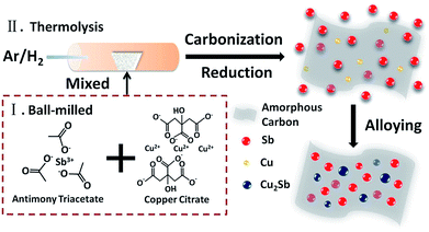
The synthesis strategy of Sb/Cu2Sb/C composite is proposed via a synchronous reduction and organic group, citric acid radical, decomposed process, as illustrated in Scheme 1. Firstly, the antimony triacetate and copper citrate with a mole ratio of 4![[thin space (1/6-em)]](https://www.rsc.org/images/entities/char_2009.gif) :
:![[thin space (1/6-em)]](https://www.rsc.org/images/entities/char_2009.gif) 1 were adequately mixed by the ball-milled procedure. Then, the mixture was placed in the tube furnace and treated under a continuous argon/hydrogen gas (9
1 were adequately mixed by the ball-milled procedure. Then, the mixture was placed in the tube furnace and treated under a continuous argon/hydrogen gas (9![[thin space (1/6-em)]](https://www.rsc.org/images/entities/char_2009.gif) :
:![[thin space (1/6-em)]](https://www.rsc.org/images/entities/char_2009.gif) 1/v
1/v![[thin space (1/6-em)]](https://www.rsc.org/images/entities/char_2009.gif) :
:![[thin space (1/6-em)]](https://www.rsc.org/images/entities/char_2009.gif) v) at 700 °C with a heating rate of 4 °C min−1 and held at this temperature for 2 h. During the reaction, the Cu nanoparticles and carbon layers were obtained from the reduction and thermolysis of copper citrate. Meanwhile, the reduction and thermolysis from antimony triacetate to Sb was also proceeded. Finally, with the increased reaction time, Cu nanoparticles were gradually and fully alloyed with Sb to form Cu2Sb nanoparticles, thus the Sb/Cu2Sb/C composite was obtained. To confirm the amorphous carbon layers, the pure copper citrate was thermolyzed under the same experimental condition. As shown in SEM (Fig. S1†), Cu particles wrapped in carbon further reveals the carbon layers is resulted from the thermolysis of copper citrate.
v) at 700 °C with a heating rate of 4 °C min−1 and held at this temperature for 2 h. During the reaction, the Cu nanoparticles and carbon layers were obtained from the reduction and thermolysis of copper citrate. Meanwhile, the reduction and thermolysis from antimony triacetate to Sb was also proceeded. Finally, with the increased reaction time, Cu nanoparticles were gradually and fully alloyed with Sb to form Cu2Sb nanoparticles, thus the Sb/Cu2Sb/C composite was obtained. To confirm the amorphous carbon layers, the pure copper citrate was thermolyzed under the same experimental condition. As shown in SEM (Fig. S1†), Cu particles wrapped in carbon further reveals the carbon layers is resulted from the thermolysis of copper citrate.
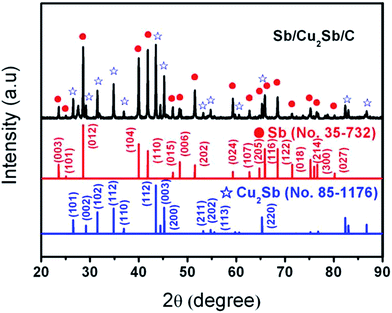
The phase of as-synthesized Sb/Cu2Sb/C sample was confirmed by X-ray diffraction (XRD). As shown in Fig. 1, all the diffraction peaks of Sb/Cu2Sb/C can be well indexed to Sb (JCPDS: no. 35-732) and Cu2Sb (JCPDS: no. 85-1176), without any impurity peaks. This indicates that the good crystal structure of Sb and the well formation of Cu2Sb from the alloy between Sb and Cu. It should be noted that there is no diffraction peaks of crystallized carbon further indicating the amorphous phase for carbon layers.
Fig. 2a displays the SEM image of synthesized Sb/Cu2Sb/C composite. Particles composed of Sb and Cu2Sb with diameter ranging from 10 nm to 260 nm decorated on the amorphous carbon layers or were wrapped by in carbon layers. To confirm the mole ratio of each element, EDX of Sb/Cu2Sb/C was carried out (Fig. 2b). As expected, the peaks of C, Si, Cu and Sb can be well indexed. It should be noted that the existence of Si is due to the use of Si substrate. The mole ratio of C, Cu and Sb are 2.25, 22.06 and 75.69 at%, respectively. Based on the XRD result, the Cu element all comes from Cu2Sb, so the Sb element mole ratio from Cu2Sb is about 11.03 at%, and the pure Sb element is about 64.66 at%. Therefore, the mole ratio of Cu2Sb and Sb in the composite is about 1![[thin space (1/6-em)]](https://www.rsc.org/images/entities/char_2009.gif) :
:![[thin space (1/6-em)]](https://www.rsc.org/images/entities/char_2009.gif) 6, indicating the small amount of Cu2Sb outside Sb particles. To get the detailed morphology and crystallinity of Sb/Cu2Sb/C, the TEM (Fig. 2c) and high-resolution TEM (HRTEM, Fig. 2d) studies were also carried out. As can be seen, the adjacent lattice plane observed in Sb/Cu2Sb/C are about 0.31 and 0.62 nm, which agrees well with d-spacing values of the (012) plane of Sb and the (001) plane of Cu2Sb, respectively.18,25
6, indicating the small amount of Cu2Sb outside Sb particles. To get the detailed morphology and crystallinity of Sb/Cu2Sb/C, the TEM (Fig. 2c) and high-resolution TEM (HRTEM, Fig. 2d) studies were also carried out. As can be seen, the adjacent lattice plane observed in Sb/Cu2Sb/C are about 0.31 and 0.62 nm, which agrees well with d-spacing values of the (012) plane of Sb and the (001) plane of Cu2Sb, respectively.18,25
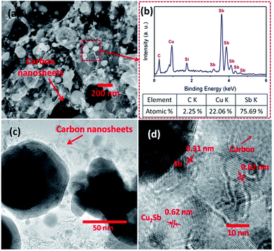 | ||
| Fig. 2 (a) SEM image of Sb/Cu2Sb/C composite. (b) The EDX pattern and mole ratio of Sb/Cu2Sb/C composite. (c) TEM and (d) HRTEM diagram of Sb/Cu2Sb/C composite. | ||
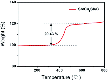
Fig. 3 displays the TGA result of Sb/Cu2Sb/C measured from 25 to 800 °C with a rate of 10 °C min−1 in air. As can be seen, there is an increased weight of 20.43 wt% from 200 °C to 600 °C. This enlarged weight of the composite is mainly attributed to the results from the increase of the completely oxidization of Sb and Cu2Sb to form CuO and Sb2O3, and the decrease due to the oxidization of the amorphous carbon. The detailed calculation of these three parts are shown in ESI.†
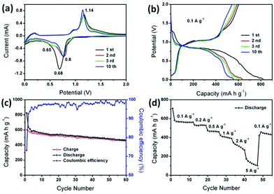
The electrochemical properties of Sb/Cu2Sb/C composite were tested as an anode material for LIBs (Fig. 4). Fig. 4a shows CV curve of the Sb/Cu2Sb/C electrode at a scanning rate of 0.25 mV s−1 between 0.01 and 2 V (vs. Li/Li+). There is an obvious couple of cathodic/anodic peaks located at around 0.68/1.14 V in the initial cycle, which could be attributed to the lithiation and delithiation reactions of both Sb and Cu2Sb to Li3Sb, respectively. For Sb, the lithiation process mainly includes two steps of Sb into Li2Sb (eqn (1)) at 0.8 V and Li2Sb into Li3Sb (eqn (2)) at 0.7 V.26–28 For Cu2Sb, two steps is also included, namely Cu2Sb to Li2CuSb (eqn (3)) at 0.8 V and Li2CuSb to Li3Sb (eqn (4)) at 0.65 V.29 After the lithiation, the delithiation reaction at 1.04 V indicated Li3Sb back to both Sb and Cu2Sb (eqn (5) and (6)). The delithiation peaks in the subsequent cathodic cycles were clearly separated into two peaks at 0.65 and 0.8 V, further indicating the formation process of Sb and Cu2Sb, respectively. Moreover, the well overlapped anodic and cathodic peaks after the first cycle further demonstrate the good cycling stability. Furthermore, Fig. 4b exhibits the charge and discharge curves. The voltage plateaus are almost in accordance with the peaks of CV (Fig. 4a). The corresponding electrochemical reactions of Sb/Cu2Sb/C composite can be listed as follows:
Discharge:
| Sb: Sb + 2Li+ + 2e− → Li2Sb | (1) |
| Li2Sb + Li+ + e− → Li3Sb | (2) |
| Cu2Sb: Cu2Sb + 2Li+ + 2e− → Li2CuSb + Cu | (3) |
| Li2CuSb + Li+ + e− → Li3Sb + Cu | (4) |
Charge:
| Sb: Li3Sb → 3Li+ + 3e− + Sb | (5) |
| Cu2Sb: Li3Sb + 2Cu → 3Li+ + 3e− + Cu2Sb | (6) |
The electrochemical performance of Sb/Cu2Sb/C composite for LIBs was shown in Fig. 4c and d. As shown in Fig. 4c, at a current density of 0.1 A g−1, the initial discharge and charge capacities are 822 and 602 mA h g−1, respectively, corresponding to a coulombic efficiency (CE) of 73.2%. From the second cycle onward, the CE steadily increases to nearly 99% and the reversible capacity retains 461 mA h g−1 after 60 cycles. The Sb/Cu2Sb/C composite also exhibited high rate performance (Fig. 4d). As the current density increased from 0.1 to 5 A g−1, the reversible capacity changes from 561 to 173 mA h g−1, respectively. Since the current density backs to 0.1 A g−1, the reversible capacity can be recovered to 430 mA h g−1, indicating good cycling stability of Sb/Cu2Sb/C electrode. The stable electrochemical properties of Sb/Cu2Sb/C composite anode materials for lithium storage can be attributed to the synchronously formed Cu2Sb nanoparticles and amorphous carbon layers matrix, which can effectively increase the stability of the structure and accommodate the volume change of Sb nanocrystals during the repeated insertion/extraction processes.
4. Conclusions
In summary, we have successfully fabricated the Sb/Cu2Sb/C composite using a high-temperature solid-phase method. This method involves the synchronously formed amorphous carbon layers matrix and Cu2Sb particles that can effectively accommodate the volume changes of Sb during electrochemical cycles and improve the conductivity of the Sb/Cu2Sb/C electrode. As a result, Sb/Cu2Sb/C as anode for LIBs exhibits a high initial reversible capacity of 602 mA h g−1 at 0.1 A g−1 and maintains 461 mA h g−1 after 60 cycles, indicating the excellent anode performance of Sb/Cu2Sb/C. In addition, the synthetic procedure of Sb/Cu2Sb/C is facile and cost effective, which may provide a new way to explore other anode materials for LIBs or even sodium ion batteries (SIBs).Acknowledgements
This work was supported by the National Natural Science Foundation of China (Grant No. 51302079 and 21401140). We also acknowledge the financial support of Hunan Provincial Innovation Foundation for Postgraduates (Grant No. 521293150) and the Foundation of Introducing Talents to Tianjin Normal University (5RL126).Notes and references
- W. Guo, X. Li, J. T. Xu, H. K. Liu, J. M. Ma and S. X. Dou, Electrochim. Acta, 2016, 188, 414–420 CrossRef CAS.
- Y. Cai, X. Li, L. Wang, H. Y. Gao, Y. N. Zhao and J. M. Ma, J. Mater. Chem. A, 2015, 3, 1396–1399 CAS.
- L. Mei, M. L. Mao, S. L. Chou, H. K. Liu, S. X. Dou, D. H. L. Ng and J. M. Ma, J. Mater. Chem. A, 2015, 3, 21699–21705 CAS.
- Z. Q. Zhu, S. W. Wang, J. Du, Q. Jin, T. R. Zhang, F. Y. Chen and J. Chen, Nano Lett., 2014, 14, 153–157 CrossRef CAS PubMed.
- Y. Q. Wang, L. Gu, Y. G. Guo, H. Li, X. Q. He, S. Tsukimoto, Y. Ikuhara and L. J. Wan, J. Am. Chem. Soc., 2012, 134, 7874–7879 CrossRef CAS PubMed.
- V. Etacheri, R. Marom, R. Elazari, G. Salitra and D. Aurbach, Energy Environ. Sci., 2011, 4, 3243–3262 CAS.
- W. Guo, X. Li, D. H. L. Ng and J. M. Ma, RSC Adv., 2015, 5, 96681–96684 RSC.
- C. Y. Cui, X. Li, Z. Hu, J. T. Xu, H. K. Liu and J. M. Ma, RSC Adv., 2015, 5, 92506–92514 RSC.
- X. Tang, Y. H. Wei, H. N. Zhang, F. L. Yan, M. Zhuo, C. M. Chen, P. Y. Xiao, J. J. Liang and M. Zhang, Electrochim. Acta, 2015, 186, 223–230 CrossRef CAS.
- G. H. Zhang, J. Zhu, W. Zeng, S. C. Hou, F. L. Gong, F. Li, C. C. Li and H. G. Duan, Nano Energy, 2014, 9, 61–70 CrossRef CAS.
- H. S. Hou, M. J. Jing, Y. C. Yang, Y. R. Zhu, L. B. Fang, W. X. Song, C. C. Pan, X. M. Yang and X. B. Ji, ACS Appl. Mater. Interfaces, 2014, 6, 16189–16196 CAS.
- J. Qin, C. N. He, N. Q. Zhao, Z. Y. Wang, C. S. Shi, E. Z. Liu and J. J. Li, ACS Nano, 2014, 8, 1728–1738 CrossRef CAS PubMed.
- D. H. Nam, K. S. Hong, S. J. Lim and H. S. Kwon, J. Power Sources, 2014, 247, 423–427 CrossRef CAS.
- Y. L. Ding, C. Wu, P. Kopold, P. A. van Aken, J. Maier and Y. Yu, Small, 2015, 11, 6026–6035 CrossRef CAS PubMed.
- A. Birrozzi, F. Maroni, R. Raccichini, R. Tossici, R. Marassi and F. Nobili, J. Power Sources, 2015, 294, 248–253 CrossRef CAS.
- K. D. Kepler, J. T. Vaughey and M. M. Thackeray, Electrochem. Solid-State Lett., 1999, 2, 307–309 CrossRef CAS.
- M. M. Thackeray, J. T. Vaughey, C. S. Johnson, A. J. Kropf, R. Benedek, L. M. L. Fransson and K. Edstrom, J. Power Sources, 2003, 113, 124–130 CrossRef CAS.
- Y. He, L. Huang, X. Li, Y. Xiao, G. L. Xu, J. T. Li and S. G. Sun, J. Mater. Chem., 2011, 21, 18517–18519 RSC.
- R. M. Gnanamuthu, Y. N. Jo and C. W. Lee, Curr. Appl. Phys., 2013, 13, 1454–1458 CrossRef.
- W. M. Zhang, J. S. Hu, Y. G. Guo, S. F. Zheng, L. S. Zhong, W. G. Song and L. J. Wan, Adv. Mater., 2008, 20, 1160–1165 CrossRef CAS.
- J. Hassoun, G. Derrien, S. Panero and B. Scrosati, Adv. Mater., 2008, 20, 3169–3175 CrossRef CAS.
- W. Guo, X. Li, D. H. L. Ng and J. M. Ma, RSC Adv., 2015, 5, 96681–96684 RSC.
- T. Yang, H. N. Zhang, Y. Z. Luo, L. Mei, D. Guo, Q. H. Li and T. H. Wang, Electrochim. Acta, 2015, 158, 327–332 CrossRef CAS.
- W. H. Li, Z. Z. Yang, Y. Jiang, Z. R. Yu, L. Gu and Y. Yu, Carbon, 2014, 78, 455–462 CrossRef CAS.
- H. L. Lv, S. Qiu, G. X. Lu, Y. Fu, X. Y. Li, C. X. Hu and J. R. Liu, Electrochim. Acta, 2015, 151, 214–221 CrossRef CAS.
- L. Fan, J. J. Zhang, J. H. Cui, Y. C. Zhu, J. W. Liang, L. L. Wang and Y. T. Qian, J. Mater. Chem. A, 2015, 3, 3276–3280 CAS.
- A. Darwiche, C. Marino, M. T. Sougrati, B. Fraisse, L. Stievano and L. Monconduit, J. Am. Chem. Soc., 2012, 134, 20805–20811 CrossRef CAS PubMed.
- M. He, K. Kravchyk, M. Walter and M. V. Kovalenko, Nano Lett., 2014, 14, 1255–1262 CrossRef CAS PubMed.
- M. Morcrette, D. Larcher, J. M. Tarascon, K. Edstrom, J. T. Vaughey and M. M. Thackeray, Electrochim. Acta, 2007, 52, 5339–5345 CrossRef CAS.
Footnote |
| † Electronic supplementary information (ESI) available. See DOI: 10.1039/c6ra14072f |
| This journal is © The Royal Society of Chemistry 2016 |

