Coupling interconnected MoO3/WO3 nanosheets with a graphene framework as a highly efficient anode for lithium-ion batteries†
Pengbo
Wang
,
Zhihua
Cheng
,
Guiqin
Lv
*,
Liangti
Qu
 * and
Yang
Zhao
 *
*
Key Laboratory of Photoelectronic/Electrophotonic Conversion Materials, Key Laboratory of Cluster Science, Ministry of Education of China, School of Chemistry and Chemical Engineering, Beijing Institute of Technology, Beijing 100081, P. R. China. E-mail: yzhao@bit.edu.cn; lqu@bit.edu.cn; lvy@bit.edu.cn; Fax: +86 10 68918608; Tel: +86 10 68918608
First published on 27th November 2017
Abstract
A rationally assembled three-dimensional graphene framework coupled with interconnected molybdenum/tungsten oxide nanosheets (MoO3/WO3-GF) has been developed via a one-step template-free strategy. With the unique nanostructure, the obtained anode material not only exhibits a high reversible capacity of about 1000 mA h g−1, approaching the theoretical capacity of MoO3 and WO3 materials, but also shows excellent rate capability and cycling performance with negligible capacity attenuation after a long-time test. These features make it a promising candidate material for high-performance commercial lithium-ion batteries in the future.
Introduction
Lithium-ion batteries (LIBs) with a high working voltage, long cycling life,1 and low toxicity have attracted increasing attention in advanced electronic devices and electric vehicles.2 As a commonly-used anode material in commercial LIBs, graphite possesses a low capacity of 372 mA h g−1 which could not meet the ever-growing energy demands. Therefore, designing and developing favorable electrodes with high capacities and stabilities for LIBs is of great significance for practical applications.Owing to their high theoretical reversible capacities, transition metal oxides, such as CuO,3 Co3O4,4 TiO2,5 and Fe3O4,6 have been developed and applied in LIBs. Among them, molybdenum trioxide (MoO3) has received much attention in recent years, which is regarded to be one of the promising candidates for LIBs because of its extremely high theoretical specific capacity of 1111 mA h g−1,7 excellent chemical stability, environmental friendliness and safety.8 Nevertheless, MoO3 has limited application in high-performance LIBs due to its inherent low electronic conductivity and poor structural integrity.9 A great effort has been devoted to improving the energy storage performance of MoO3, including synthesizing MoO3 materials with various nanostructures, such as nanoparticles,10 nanobelts,11 nanowires,12 nanosheets,13 and nanorods,14 and modulating the electron configuration of MoO3 through the introduction of heteroatoms, metals or metal oxides into the matrix.15–18 Tungsten (W), with a similar ionic radius to that of molybdenum, is regarded as an efficient candidate to incorporate into the molybdenum lattice19 and thus to promote the conductivity of the materials because of the relatively high conductivity of the tungsten species.20 A lot of work has been carried out to introduce W into molybdenum oxide materials, and indeed the enhancement of LIB performances has been achieved.21,22 However, these studies failed to finely control the morphology of the materials, which is believed to be one of the most important factors for anode materials.23 Thus, it is still a challenge to achieve high-capacity electrode materials with a suitable nanostructure and satisfactory stability.
As a new emerging carbon material, graphene with a high specific surface area, outstanding electrical conductivity, and excellent mechanical/chemical stabilities24–26 can be introduced into a system to solve this problem. On the one hand, graphene sheets are easily arranged into specific interconnected architectures, which greatly facilitate the electron transfer within electrode materials27 and the ionic migration in the electrolyte.28 On the other hand, graphene can suppress the volume change and agglomeration of the active materials during the charge–discharge process.29 Although many efforts have been made to synthesize MoO3 or WO3/graphene hybrids,30–34 little attention has been paid to combining and assembling these materials together into specific nanostructured architectures for a highly efficient LIB performance.
In this work, we have developed a highly efficient anode material for LIBs based on the rational assembly of interconnected MoO3/WO3 nanosheets on 2D graphene sheets to form a 3D hierarchical framework (MoO3/WO3-GF) via a straightforward one-step hydrothermal method. With the merits of the hierarchical nanostructure, the as-prepared anode shows a high reversible capacity of about 1000 mA h g−1, good cycling stability and outstanding rate capability, demonstrating its great potential for advanced lithium-ion storage devices.
Results and discussion
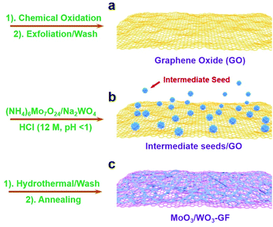
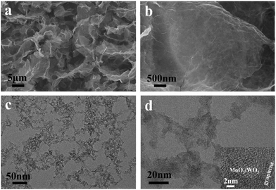
The fabrication process of the MoO3/WO3-GF is presented in Scheme 1. We first produced a well-dispersed suspension by the ultrasonic mixing of (NH4)6Mo7O24·4H2O, Na2WO4·2H2O and GO in water. After adjusting the pH value of the solution to 1 with HCl, a brown suspension was obtained with continuous ultrasonic stirring for 30 min due to the hydrolysis of Mo7O246− and WO42−. It has been reported by Meng et al.35 that metal ions can act as linkers for the pre-assembly of GO nanosheets through metal–oxygen covalent or electrostatic interactions between the metal ion and the hydrophilic groups (such as –OH and –COOH groups) of GO sheets, thus leading to the formation of a well-distributed metal-based nanostructure within a graphene hydrogel. Similarly, the intermediate hydrolyzate of Mo7O246− and WO42− could coordinate to the oxygen groups of GO sheets because of the unsaturated coordinated d orbitals of Mo and W, promoting the formation of a coupling structure of metal species and the gelation process of GO. To form the MoO3/WO3-GF, the resulting suspension was then hydrothermally treated in a 40 mL Teflon-lined autoclave at 180 °C for 10 h. After the hydrothermal treatment, GO sheets were reduced to graphene and self-assembled into a 3D framework driven by the π–π stacking interactions of graphene sheets. Finally, the freeze-dried MoO3/WO3-GF was calcined at 400 °C in Ar for 2 h to remove unstable components and increase the conductivity of graphene.As shown in Fig. 1a, the as-prepared MoO3/WO3-GF exhibits a typical 3D interconnected macroscopic structure consistent with those commonly reported 3D graphene materials,36 which provides favorable electron/mass transport pathways and prompts the electrochemical process. The enlarged scanning electron microscopy (SEM) image in Fig. 1b demonstrates that the MoO3/WO3-GF has a relatively smooth surface and loose structures without any visible aggregates, indicating that the interconnected MoO3/WO3 hybrids are uniformly distributed on graphene sheets. This is further confirmed by the following transmission electron microscopy (TEM). Fig. 1c shows that the unique hybrid structure consists of a large number of small MoO3/WO3 nanosheets which are randomly coated on the graphene basal plane. The high-resolution TEM (HRTEM) image shows that the MoO3/WO3 nanosheets with an average diameter of ∼15 nm are interconnected with each other on graphene sheets (Fig. 1d).
To investigate the formation of interconnected MoO3/WO3 nanosheets on graphene sheets, we performed a series of comparative experiments. In the absence of the tungsten species, only a 3D graphene framework with large MoO3 microrods instead of nanosheets was obtained (Fig. S1a and 1b, ESI†), and if without the Mo species, irregular and disordered structures were observed which were randomly distributed on graphene sheets (Fig. S1c and d, ESI†). Besides, the interconnected MoO3/WO3 nanosheets were also not produced if the GO suspension was absent during the hydrothermal process. Instead, large thick bulk-like MoO3/WO3 composites were obtained (Fig. S1e and f, ESI†). Interestingly, the content ratio of MoO3versus WO3 is also important for the formation of interconnected MoO3/WO3 nanosheets. As shown in Fig. S2,† when a small amount of Na2WO4·2H2O was added into the original suspension (the weight ratio of (NH4)6Mo7O24·4H2O to Na2WO4·2H2O is 2/1), large MoO3/WO3 sheets were obtained (named MoO3/WO3-GF-2/1). While with the continuous increase of the amount of Na2WO4·2H2O (the weight ratio of (NH4)6Mo7O24·4H2O to Na2WO4·2H2O is 1/2), both the MoO3/WO3 aggregates and their randomly distributed nanosheets were formed on graphene sheets (named MoO3/WO3-GF-1/2).
Based on the above experimental results, the formation mechanism was proposed. In HCl solution (pH = 1), the hydrolytic WO42− is more stable than Mo7O246−, which could first nucleate at the residue oxygen groups, defects or folds of GO nanosheets (Scheme 1a and b) to effectively minimize the interface energy barrier between the solid surface and liquid solution. This indicates that WO42− species dominate the amount of nucleation and growth of nanocrystals. Meanwhile, the free Mo7O246− could then be coupled to the WO42− to form mixed crystal seeds on graphene sheets because of the similar radius of Mo6+ (0.059 nm) and W6+ (0.060 nm) during the hydrothermal treatment, thus leading to the efficient oriented growth of interconnected MoO3/WO3 nanosheets on graphene basal planes (Scheme 1c). The production of larger amounts of MoO3/WO3-GF is possible by scale up of the autoclave (Fig. S3a†) and the yield of MoO3/WO3-GF is 62% compared with the overall raw material.
The X-ray diffraction (XRD) pattern of the MoO3/WO3-GF is investigated in comparison with MoO3/WO3, MoO3-GF and WO3-GF. As shown in Fig. 2a and Fig. S3b,† the hydrothermally-formed MoO3/WO3 composite exhibits a series of typical diffraction peaks, in which the peaks at 22.6°, 26.2° and 32.9° correspond to ε-MoO3 (JCPDS no. 09-0209) and the peaks at 22.8°, 24.0°, 28.2° and 46.5° belong to tetragonal WO3 (JCPDS no. 05-0388), consistent with the previously reported work.37 Similar to the diffraction peaks of the MoO3/WO3 composite, the as-prepared MoO3/WO3-GF exhibits weak broad and coarse peaks, indicating the formation of amorphous or mixed crystals. In addition, no obvious peak related to the graphene is observed in the MoO3/WO3-GF, which is probably attributed to the low restacking of graphene sheets38 and the coverage of metal oxides.39 However, unlike the reflections of MoO3/WO3 and MoO3/WO3-GF, the initial MoO3-GF and WO3-GF exhibit totally different narrow diffraction peaks (Fig. S4, ESI†), in which the peaks of MoO3 in MoO3-GF are indexed to orthorhombic MoO3 (JCPDS no. 05-0508), while the peaks of WO3 in WO3-GF belong to the hexagonal WO3 (JCPDS card no. 33-1387). These results imply that the co-existence of Mo and W has an impact on each other during the formation of metal oxides because of the similar ionic radius of Mo and W, and the high lattice matching of MoO3 and WO3 with similar crystalline structures.19,40 The elemental mapping exhibits the well-distributed C, O, W and Mo elements over the MoO3/WO3-GF (Fig. 2b and c), indicating that the MoO3/WO3 hybrids are successfully formed and uniformly attached to graphene sheets. Thermogravimetric analysis (TGA) was performed to evaluate the thermal stability and determine the composition of MoO3/WO3-GF (Fig. S5, ESI†). The weight loss of less than 1% at temperatures of up to 200 °C is attributed to the removal of physically adsorbed water. The fast mass loss of ∼23% from 300 to 550 °C can be ascribed to the combustion of the graphene nanosheets and a weight loss at a temperature above 700 °C corresponds to the evaporation of MoO3 species. Therefore, the mass fraction of MoO3/WO3 is calculated to be ∼76%. Besides, inductively coupled plasma-atomic emission spectroscopy (ICP-AES) was also conducted, which reveals the molybdenum and tungsten elemental contents of 26.9% and 24.2%, respectively. Therefore, the corresponding mass fractions of MoO3, WO3 and graphene were determined to be 40.5%, 30.5% and 29%, respectively.
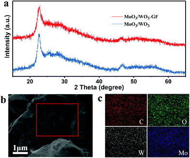 | ||
| Fig. 2 (a) XRD patterns of MoO3/WO3-GF and MoO3/WO3 composites. (b) The SEM image of MoO3/WO3-GF and (c) the corresponding C-, O-, W-, and Mo-elemental mappings. | ||
To further investigate the covalent state of the elements and the oxidation states of the samples, we conducted XPS measurement. As expected, the X-ray photoelectron spectroscopy (XPS) in Fig. 3a shows a series of pronounced Mo- and W-related peaks along with the obvious C 1s and O 1s peaks. The atomic ratio of Mo and W for the MoO3/WO3-GF is calculated to be 1/0.6. The two typical Mo peaks located at 232.5 and 235.8 eV are observed in the high-resolution Mo 3d spectrum, which belong to the binding energies of the Mo(VI) 3d3/2 and 3d5/2 electrons, respectively (Fig. 3b). The high-resolution W 4f spectrum (Fig. 3c) reveals two peaks at 35.8 and 37.9 eV, which could be ascribed to W 4f7/2 and 4f5/2 of the W(VI) oxide state in agreement with the previous work.19 Besides, the high-resolution C 1s spectrum (Fig. 3d) exhibits four typical peaks including C–C (284.75 eV), C–O–C (C–O–H) (286.26 eV), C![[double bond, length as m-dash]](https://www.rsc.org/images/entities/char_e001.gif) O (287.78 eV), and O
O (287.78 eV), and O![[double bond, length as m-dash]](https://www.rsc.org/images/entities/char_e001.gif) C–OH (289.34 eV). The nitrogen adsorption–desorption isotherm obtained from the Brunauer–Emmett–Teller (BET) analysis (Fig. S6, ESI†) reveals the mesoporous structure of MoO3/WO3-GF with a specific surface area of 46.25 m2 g−1, a pore volume of 0.061 cm3 g−1, and an average pore diameter of 3.79 nm, which could facilitate the lithium ion and electron transportation.
C–OH (289.34 eV). The nitrogen adsorption–desorption isotherm obtained from the Brunauer–Emmett–Teller (BET) analysis (Fig. S6, ESI†) reveals the mesoporous structure of MoO3/WO3-GF with a specific surface area of 46.25 m2 g−1, a pore volume of 0.061 cm3 g−1, and an average pore diameter of 3.79 nm, which could facilitate the lithium ion and electron transportation.
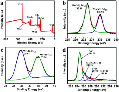 | ||
| Fig. 3 (a) XPS spectrum of the as-prepared MoO3/WO3-GF, and the corresponding high-resolution (b) Mo 3d, (c) W4f, and (d) C 1s peaks. | ||
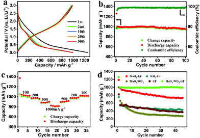
The MoO3/WO3-GF with unique interconnected nanostructures is expected to be an efficient anode material in LIBs. Fig. 4a shows the discharge/charge profiles of the MoO3/WO3-GF at 200 mA g−1 over the potential range of 3.0–0.001 V (versus Li+/Li). As can be seen, an initial discharge capacity reaches ∼1262.9 mA h g−1. It remains at a relatively high level of ∼999.6 mA h g−1 over 50 cycles, which is far higher than their corresponding theoretical capacity of ∼860 mA h g−1 (calculated based on the ICP-AES results), indicating the synergistic effect between MoO3/WO3 and graphene that would benefit the enhancement of electrochemical performance. A capacity loss of 24% for the first cycle is observed because of the trapping of some lithium ions in the MoO3/WO3 lattice and the formation of a solid electrolyte interphase (SEI) layer.41,42 Nevertheless, the steady capacity of MoO3/WO3-GF is superior to that of a commercial graphite electrode (372 mA h g−1). This is also further confirmed by its cycling stability and coulombic efficiency (Fig. 4b). As shown in Fig. 4b, the as-prepared MoO3/WO3-GF has a reversible capacity of 951.6 mA h g−1 over 100 cycles with a coulombic efficiency of 99.2%. Except for the irreversible capacity loss in the initial cycle, no obvious capacity fading can be observed in the subsequent discharge/charge cycles, suggesting an excellent cycling performance for the MoO3/WO3-GF. More importantly, the MoO3/WO3-GF also exhibits an outstanding rate capability (Fig. 4c), which delivers a series of reversible discharge capacities of 1027.8, 972.3, and 889.1 mA h g−1 at 100, 200, and 500 mA g−1, respectively. Interestingly, the discharge capacity of MoO3/WO3-GF can reach a stable value quickly and maintain a high reversible capacity of 816.3 mA h g−1 even at a high current density (1000 mA g−1), indicating the good discharge/charge stability. The discharge capacity recovers to its initial value when the current density goes back to 100 mA g−1. For comparison, the cycling performances of the MoO3/WO3-GF, MoO3-GF, WO3-GF, MoO3/WO3 and GF are also investigated at 200 mA g−1 (Fig. 4d). Unlike the counterparts, for which the capacities of these LIBs have sharp declines in the first 5 cycles, the MoO3/WO3-GF exhibits a stable reversible capacity with no obvious decrease from the second cycle, indicating the remarkable retention of capacity.
Cyclic voltammetry (CV) of the MoO3/WO3-GF anode was conducted at a scan rate of 0.2 mV s−1 over the potential range of 3.0–0 V (versus Li+/Li) to inspect the electrochemical Li-ion storage during the discharging/charging process (Fig. 5a). An inconspicuous redox peak at ∼0.7 V is observed in the first discharge cycle and disappeared in the following cycles, which can be attributed to the irreversible decomposition of the electrolyte and the formation of the SEI layer. In comparison with the graphene reported previously,43 the reversible peaks between 1.2 and 1.7 V are probably due to the Li+ ion insertion/extraction process in the lattice of MoO3/WO3 nanosheets. These dominant peaks indicate the available active storage sites which contribute to the high capacity. In addition, the CV curves remain almost unchanged from the second cycle, indicating that the highly reversible Li ion insertion/extraction of the MoO3/WO3-GF could be achieved quickly. In fact, the different MoO3/WO3 ratios on graphene sheets (such as MoO3/WO3-GF-2/1 and MoO3/WO3-GF-1/2) can also be a factor to affect the battery performances (Fig. S7, ESI†). For example, both MoO3/WO3-GF-2/1 and MoO3/WO3-GF-1/2 electrodes show a sharp capacity loss of 31% and 43% for the first five cycles, respectively (see the detailed discussion in the ESI†). Moreover, the reversible discharge capacities of MoO3/WO3-GF-2/1 and MoO3/WO3-GF-1/2 are 619.8 and 393.1 mA h g−1 at 200 mA g−1 over 30 cycles, respectively, which are far lower than the as-prepared MoO3/WO3-GF material (Fig. 4b). This is probably ascribed to the large MoO3/WO3 crystal size and disordered structures, thus leading to decreased Li-ion storage sites.
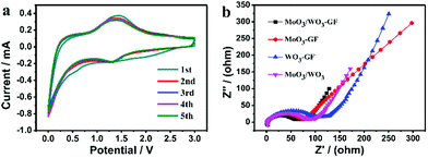 | ||
| Fig. 5 (a) CV curves of MoO3/WO3-GF at a scan rate of 0.2 mV s−1, and (b) the EIS of MoO3/WO3-GF, MoO3-GF, WO3-GF and MoO3/WO3 before cycling. | ||
The charge storage mechanism can be characterized by the sweep voltammetry method.44 We assume that the relationship between the current (i) and scan rate (v) obeys the power law:45,46
| i = avb | (1) |
The overall pseudocapacitive contribution proportion can be calculated by the following equation47–49
| i(V) = k1v + k2v1/2 | (2) |
For analytical purposes, eqn (2) can be changed into
| i(V)/v1/2 = k1v1/2 + k2 | (3) |
In order to further understand the kinetic process, the electrochemical impedance spectra (EIS) of MoO3/WO3-GF, MoO3-GF, WO3-GF and MoO3/WO3 were obtained in the frequency range from 10−2 Hz to 106 Hz before cycling. Fig. 5b shows the Nyquist plots of the samples. The MoO3/WO3-GF possesses the smallest semicircle diameter among all the compared samples in the high- and medium-frequency regions, indicating the low resistance of the electrolyte and the fast charge transfer reaction for the MoO3/WO3-GF anode. The slope lines in the low frequency region reflect the Warburg impedance of the Li-ion diffusion. Interestingly, a significantly decreased semicircle in the EIS spectrum can be observed over 100 cycles (Fig. S9, ESI†), indicating a decrement of charge transfer resistance during cycling. The improved electrochemical kinetics is probably attributed to an effective activation between the electrode material and electrolyte, and gradual conversion of MoO3/WO3 from the crystalline to the amorphous state during the Li ion insertion/extraction process,16,50 which has been regarded to be beneficial for the battery performance.51 No changes in the morphologies of the MoO3/WO3 nanosheets on graphene sheets are observed after 100 cycles (Fig. S10, ESI†), demonstrating the good cycling performance of MoO3/WO3-GF with high structural stability. The good battery performance of MoO3/WO3-GF can be attributed to the following aspects: (1) the unique interconnected MoO3/WO3 nanosheet structures evenly anchored on the graphene basal plane provide plenty of Li-ion storage sites and increase the accessible reactive surface area, thus leading to an enhanced electrochemical process. (2) It is reported that the MoO3/WO3 sheets have a relatively higher conductivity than other types of transition-metal oxides,20 which can serve as an efficient electron transport pathway. After coupling with graphene, the as-prepared anode material offers small internal resistances and a fast charge flow to achieve a high-rate discharging/charging performance. (3) The porous graphene framework with high chemical/mechanical stability buffers the volume variation during the lithiation/delithiation process which overcomes the usual structural collapse of bulk materials, thus demonstrating excellent Li-storage stability.
In summary, a well-designed MoO3/WO3-GF material has been successfully synthesized through a facile hydrothermal approach, in which the interconnected MoO3/WO3 nanosheets are evenly dispersed on graphene sheets. With the merits of the hierarchical nanostructure, the resulting material can be directly used as the anode for LIBs which exhibits high specific capacity, good cycling stability and excellent rate capability. The enhanced electrochemical performances can be ascribed to the synergistic effect of the nanostructured MoO3/WO3 hybrids and the highly conductive graphene framework.
Experimental
Synthesis of MoO3/WO3-GF
Graphite oxide (GO) was synthesized by a modified Hummers’ method.52 To synthesize the MoO3/WO3-GF, 0.25 g ammonium molybdate tetrahydrate ((NH4)6Mo7O24·4H2O) and 0.23 g sodium tungstate dihydrate (Na2WO4·2H2O) were firstly dissolved in 30 mL deionized water, followed by the addition of graphite oxide (120 mg). The pH of the resulting suspension was then regulated to be ∼1 by adding HCl solution, which was then transferred into a 40 mL Teflon-line autoclave and treated at 180 °C for 10 h after ultrasonic stirring for 30 min. After washing with deionized water several times, the MoO3/WO3-GF was finally obtained by annealing the freeze-dried sample at 400 °C with a ramp of 1 °C min−1 for 2 h under an argon atmosphere. The yield of the as-prepared MoO3/WO3-GF determined turned out to be about 62% by calculating the weight ratio of the final product (∼0.37 g) to the raw material (∼0.6 g). Besides, MoO3/WO3-GF-2/1, MoO3/WO3-GF-1/2, MoO3-GF, WO3-GF, MoO3/WO3 and GF were also prepared under the same conditions for comparison.Characterization
The morphology of the sample was detected by scanning (SEM, JSM-7500F) and transmission electron microscopies (TEM, JEM, 2100). The elemental mappings were carried out on a SEM unit with a high-angle annular dark-field (HAADF) detector (HITACHI S-5500) operating at 30 kV. X-ray diffraction (XRD) patterns were obtained by using a Netherlands 1710 diffractometer with a Cu Kα irradiation source (λ = 1.54 Å). X-ray photoelectron spectroscopy (XPS) was performed with an ESCALab220i-XL electron spectrometer from VG Scientific using 300 W Al Kα radiation. The base pressure was about 3 × 10⁻⁹ mbar. The binding energies were referenced to the C 1s line at 284.8 eV from adventitious carbon. The BET specific surface area was determined by nitrogen adsorption–desorption isotherm measurements at 77 K (NOVA 2200e). Before the adsorption measurements, the samples were degassed under vacuum at 573 K for 3 h. Thermogravimetric analysis (TGA) was carried out by using a thermobalance (TGA2050) from room temperature to 1000 °C at a rate of 10 °C min−1 under a continuous air flow. The element proportion was determined based on Optima 8300 Inductively Coupled Plasma-Atomic Emission Spectrometry (ICP-AES, PerkinElmer).Electrochemical measurements
Electrochemical performance measurements were carried out using standard CR2025 coin cells at room temperature. Anode materials were prepared by mixing active materials (MoO3/WO3-GF, MoO3-GF, WO3-GF, MoO3/WO3 and GF), acetylene black (conducting agent) and polyvinylidene fluoride (PVDF, binder) in a weight ratio of 8![[thin space (1/6-em)]](https://www.rsc.org/images/entities/char_2009.gif) :
:![[thin space (1/6-em)]](https://www.rsc.org/images/entities/char_2009.gif) 1
1![[thin space (1/6-em)]](https://www.rsc.org/images/entities/char_2009.gif) :
:![[thin space (1/6-em)]](https://www.rsc.org/images/entities/char_2009.gif) 1 in N-methyl-2-pyrrolidinone (NMP) to form a homogeneous slurry. Then, the slurry was uniformly pasted on a copper foil (current collector) and dried in a vacuum oven at 120 °C overnight. The loading density of the MoO3/WO3-GF on the current collector is calculated to be approximately 1.3 mg cm−2. Testing cells were assembled in an Ar-filled glove box using Li foils as both counter electrodes and reference electrodes. Celgard 2400 membranes were used as separators and 1 M LiPF6 solution in a mixture of ethylene carbonate and dimethyl carbonate (EC/DMC, 1
1 in N-methyl-2-pyrrolidinone (NMP) to form a homogeneous slurry. Then, the slurry was uniformly pasted on a copper foil (current collector) and dried in a vacuum oven at 120 °C overnight. The loading density of the MoO3/WO3-GF on the current collector is calculated to be approximately 1.3 mg cm−2. Testing cells were assembled in an Ar-filled glove box using Li foils as both counter electrodes and reference electrodes. Celgard 2400 membranes were used as separators and 1 M LiPF6 solution in a mixture of ethylene carbonate and dimethyl carbonate (EC/DMC, 1![[thin space (1/6-em)]](https://www.rsc.org/images/entities/char_2009.gif) :
:![[thin space (1/6-em)]](https://www.rsc.org/images/entities/char_2009.gif) 1 v/v) as the electrolyte. Galvanostatic charge–discharge cycling of all the assembled half-cells was carried out in the potential range of 0.001–3.0 V (vs. Li/Li+) using the Neware battery tester. Cyclic voltammetry (CV) at a scan rate of 0.2 mV s−1 over the potential range of 0–3 V (vs. Li/Li+) and electrochemical impedance spectra (EIS) in a range of 0.01 Hz to 1 M Hz were measured on a 660E electrochemical workstation.
1 v/v) as the electrolyte. Galvanostatic charge–discharge cycling of all the assembled half-cells was carried out in the potential range of 0.001–3.0 V (vs. Li/Li+) using the Neware battery tester. Cyclic voltammetry (CV) at a scan rate of 0.2 mV s−1 over the potential range of 0–3 V (vs. Li/Li+) and electrochemical impedance spectra (EIS) in a range of 0.01 Hz to 1 M Hz were measured on a 660E electrochemical workstation.
Conflicts of interest
There are no conflicts to declare.Acknowledgements
We are thankful for the financial support from the National Key R&D Program of China (2017YFB1104300), NSFC (21604003, 21325415 and 51673026), the Beijing Natural Science Foundation (2164070, 2152028), the Beijing Municipal Science and Technology Commission (Z161100002116022), and 111 Project 807012.References
- B. Scrosati, Nature, 1995, 373, 557–558 CrossRef CAS.
- J.-M. Tarascon and M. Armand, Nature, 2001, 414, 359–367 CrossRef CAS PubMed.
- J. C. Park, J. Kim, H. Kwon and H. Song, Adv. Mater., 2009, 21, 803–807 CrossRef CAS.
- Z. S. Wu, G. M. Zhou, L. C. Yin, W. C. Ren, F. Li and H. M. Cheng, Nano Energy, 2012, 1, 107–131 CrossRef CAS.
- Y. X. Tang, Y. Y. Zhang, J. Y. Deng, D. P. Qi, W. R. Leow, J. Q. Wei, S. Y. Yin, Z. L. Dong, R. Yazami, Z. Chen and X. D. Chen, Angew. Chem., Int. Ed., 2014, 53, 13488–13492 CrossRef CAS PubMed.
- C. N. He, S. Wu, N. Q. Zhao, C. S. Shi, E. Z. Liu and J. J. Li, ACS Nano, 2013, 7, 4459–4469 CrossRef CAS PubMed.
- C. Wang, L. X. Wu, H. Wang, W. H. Zuo, Y. Y. Li and J. P. Liu, Adv. Funct. Mater., 2015, 25, 3524–3533 CrossRef CAS.
- M. A. Ibrahem, F.-Y. Wu, D. A. Mengistie, C.-S. Chang, L.-J. Li and C. W. Chu, Nanoscale, 2014, 6, 5484–5490 RSC.
- K. Zhou, W. J. Zhou, X. J. Liu, Y. H. Sang, S. Z. Ji, W. Li, J. Lu, L. G. Li, W. H. Niu, H. Liu and S. W. Chen, Nano Energy, 2015, 12, 510–520 CrossRef CAS.
- S.-H. Lee, Y.-H. Kim, R. Deshpande, P. A. Parilla, E. Whitney, D. T. Gillaspie, K. M. Jones, A. H. Mahan, S. B. Zhang and A. C. Dillon, Adv. Mater., 2008, 20, 3627–3632 CrossRef CAS.
- L. Q. Mai, B. Hu, W. Chen, Y. Y. Qi, C. S. Lao, R. S. Yang, Y. Dai and Z. L. Wang, Adv. Mater., 2007, 19, 3712–3716 CrossRef CAS.
- P. Meduri, E. Clark, J. H. Kim, E. Dayalan, G. U. Sumanasekera and M. K. Sunkara, Nano Lett., 2012, 12, 1784–1788 CrossRef CAS PubMed.
- M. B. Sreedhara, A. L. Santhosha, A. J. Bhattacharyya and C. N. R. Rao, J. Mater. Chem. A, 2016, 4, 9466–9471 CAS.
- J. S. Chen, Y. L. Cheah, S. Madhavi and X. W. Lou, J. Phys. Chem. C, 2010, 114, 8675–8678 CAS.
- W. Wang, J. W. Qin, Z. G. Yin and M. H. Cao, ACS Nano, 2016, 10, 10106–10116 CrossRef CAS PubMed.
- J. Y. Yao, Y. J. Gong, S. B. Yang, P. Xiao, Y. H. Zhang, K. Keyshar, G. L. Ye, S. Ozden, R. Vajtai and P. M. Ajayan, ACS Appl. Mater. Interfaces, 2014, 6, 20414–20422 CAS.
- X. J. Wang, R. Nesper, C. Villevieille and P. Novák, Adv. Energy Mater., 2013, 3, 606–614 CrossRef CAS.
- L. Q. Mai, F. Yang, Y. L. Zhao, X. Xu, L. Xu and Y. Z. Luo, Nat. Commun., 2011, 2, 381–385 CrossRef PubMed.
- N. X. Li, H. C. Teng, L. Zhang, J. C. Zhou and M. C. Liu, RSC Adv., 2015, 5, 95394–95400 RSC.
- X. Xiao, T. P. Ding, L. Y. Yuan, Y. Q. Shen, Q. Z. Zhong, X. H. Zhang, Y. Z. Cao, B. Hu, T. Zhai, L. Gong, J. Chen, Y. X. Tong, J. Zhou and Z. L. Wang, Adv. Energy Mater., 2012, 2, 1328–1332 CrossRef CAS.
- X. P. Fang, B. K. Guo, Y. F. Shi, B. Li, C. X. Hua, C. H. Yao, Y. C. Zhang, Y.-S. Hu, Z. X. Wang, G. D. Stucky and L. Q. Chen, Nanoscale, 2012, 4, 1541–1544 RSC.
- S. Yoon and A. Manthiram, J. Mater. Chem., 2011, 21, 4082–4085 RSC.
- Y. Y. Zhang, X. H. Rui, Y. X. Tang, Y. Q. Liu, J. Q. Wei, S. Chen, W. R. Leow, W. L. Li, Y. J. Liu, J. Y. Deng, B. Ma, Q. Y. Yan and X. D. Chen, Adv. Energy Mater., 2016, 6, 1502409 CrossRef.
- A. K. Geim and K. S. Novoselov, Nat. Mater., 2007, 6, 183–191 CrossRef CAS PubMed.
- C. Lee, X. D. Wei, J. W. Kysar and J. Hone, Science, 2008, 321, 385–388 CrossRef CAS PubMed.
- A. A. Balandin, S. Ghosh, W. Z. Bao, I. Calizo, D. Teweldebrhan, F. Miao and C. N. Lau, Nano Lett., 2008, 8, 902–907 CrossRef CAS PubMed.
- Y. X. Tang, Y. Y. Zhang, X. H. Rui, D. P. Qi, Y. F. Luo, W. R. Leow, S. Chen, J. Guo, J. Q. Wei, W. L. Li, J. Y. Deng, Y. K. Lai, B. Ma and X. D. Chen, Adv. Mater., 2016, 28, 1567–1576 CrossRef CAS PubMed.
- Y. J. Gong, S. B. Yang, Z. Liu, L. L. Ma, R. Vajtai and P. M. Ajayan, Adv. Mater., 2013, 25, 3979–3984 CrossRef CAS PubMed.
- Z.-S. Wu, W. C. Ren, L. Wen, L. B. Gao, J. P. Zhao, Z. P. Chen, G. M. Zhou, F. Li and H.-M. Cheng, ACS Nano, 2010, 4, 3187–3194 CrossRef CAS PubMed.
- P.-J. Lu, M. Lei and J. Liu, CrystEngComm, 2014, 16, 6745–6755 RSC.
- L. Noerochim, J.-Z. Wang, D. Wexler, Z. Chao and H.-K. Liu, J. Power Sources, 2013, 228, 198–205 CrossRef CAS.
- X. Y. Gu, F. L. Wu, B. B. Lei, J. Wang, Z. L. Chen, K. Xie, Y. Song, D. L. Sun, L. X. Sun, H. Y. Zhou and F. Fang, J. Power Sources, 2016, 320, 231–238 CrossRef CAS.
- F. Y. Zeng, Y. F. Ren, L. Chen, Y. Yang, Q. L. Li and G. Gu, Electrochim. Acta, 2016, 190, 964–971 CrossRef CAS.
- S. K. Park, H. J. Lee, M. H. Lee and H. S. Park, Chem. Eng. J., 2015, 281, 724–729 CrossRef CAS.
- J. J. Mao, M. Z. Ge, J. Y. Huang, Y. K. Lai, C. J. Lin, K. Q. Zhang, K. Meng and Y. X. Tang, J. Mater. Chem. A, 2017, 5, 11873–11881 CAS.
- C. G. Hu, J. L. Xue, L. Y. Dong, Y. Jiang, X. P. Wang, L. T. Qu and L. M. Dai, ACS Nano, 2016, 10, 1325–1332 CrossRef CAS PubMed.
- M. Imran, A. B. Yousaf, S. J. Zaidi and C. Fernandez, Int. J. Hydrogen Energy, 2017, 2, 152–160 Search PubMed.
- L. Fu, T. Xia, Y. H. Zheng, J. Yang, A. W. Wang and Z. Wang, Ceram. Int., 2015, 41, 5903–5908 CrossRef CAS.
- Y. J. Chen, X. P. Di, C. Ma, C. L. Zhu, P. Gao, J. Q. Li, C. W. Sun and Q. Y. Ouyang, RSC Adv., 2013, 3, 17659–17663 RSC.
- R. R. Kharade, S. S. Mali, S. S. Mohite, V. V. Kondalkar, P. S. Patil and P. N. Bhosale, Electroanalysis, 2014, 26, 2388–2397 CrossRef CAS.
- M. Ihsan, H. Q. Wang, S. R. Majid, J. P. Yang, S. J. Kennedy, Z. P. Guo and H. K. Liu, Carbon, 2016, 96, 1200–1207 CrossRef CAS.
- Y. X. Tang, J. Y. Deng, W. L. Li, O. I. Malyi, Y. Y. Zhang, X. R. Zhou, S. W. Pan, J. Q. Wei, Y. R. Cai, Z. Chen and X. D. Chen, Adv. Mater., 2017, 29, 1701828 CrossRef PubMed.
- M. H. Ye, Z. L. Dong, C. G. Hu, H. H. Cheng, H. B. Shao, N. Chen and L. T. Qu, Small, 2014, 10, 5035–5041 CAS.
- S. T. Wang, W. Quan, Z. Zhu, Y. Yang, Q. Liu, Y. Ren, X. Y. Zhang, R. Xu, Y. Hong, Z. T. Zhang, K. Amine, Z. L. Tang, J. Lu and J. Li, Nat. Commun., 2017, 8, 627–634 CrossRef PubMed.
- P. Simon, Y. Gogotsi and B. Dunn, Science, 2014, 343, 1210–1211 CrossRef CAS PubMed.
- V. Augustyn, J. Come, M. A. Lowe, J. W. Kim, P.-L. Taberna, S. H. Tolbert, H. D. Abruña, P. Simon and B. Dunn, Nat. Mater., 2013, 12, 518–522 CrossRef CAS PubMed.
- R. T. Wang, J. W. Lang, P. Zhang, Z. Y. Lin and X. B. Yan, Adv. Funct. Mater., 2015, 25, 2270–2278 CrossRef CAS.
- T. Brezesinski, J. Wang, J. Polleux, B. Dunn and S. H. Tolbert, J. Am. Chem. Soc., 2009, 131, 1802–1809 CrossRef CAS PubMed.
- H.-S. Kim, J. B. Cook, H. Lin, J. S. Ko, S. H. Tolbert, V. Ozolins and B. Dunn, Nat. Mater., 2017, 16, 454–460 CrossRef CAS PubMed.
- Z. X. Huang, Y. Wang, Y. G. Zhu, Y. M. Shi, J. I. Wong and H. Y. Yang, Nanoscale, 2014, 6, 9839–9845 RSC.
- Y. S. Jung, S. K. Lee, D. J. Ahn, A. C. Dillon and S.-H. Lee, J. Power Sources, 2009, 188, 286–291 CrossRef CAS.
- Y. Li, Y. Zhao, H. H. Cheng, Y. Hu, G. Q. Shi, L. M. Dai and L. T. Qu, J. Am. Chem. Soc., 2012, 134, 15–18 CrossRef CAS PubMed.
Footnote |
| † Electronic supplementary information (ESI) available. See DOI: 10.1039/c7nr07849h |
| This journal is © The Royal Society of Chemistry 2018 |

