
 Open Access Article
 This Open Access Article is licensed under a
 Creative Commons Attribution 3.0 Unported Licence
Atomically dispersed Co-based species containing electron withdrawing groups for electrocatalytic oxygen reduction reactions†
Yunseok Shin‡
,
Sunggu Park‡ ,
Hanbi Jang,
Gogyun Shin,
Dongha Shin and
Sungjin Park*
,
Hanbi Jang,
Gogyun Shin,
Dongha Shin and
Sungjin Park*
Department of Chemistry and Chemical Engineering, Inha University, 100 Inha-ro, Michuholgu, Incheon 22212, Republic of Korea. E-mail: sungjinpark@inha.ac.kr
First published on 22nd August 2024
Abstract
Single-atom-based catalysts are a promising catalytic system with advantages of molecular catalysts and conductive supports. In this work, a new hybrid material (CoF/NG) is produced using a low-temperature reaction between an organometallic complex (Co(C5HF6O2)2) (CoF) and N-doped reduced graphene oxide (NG). CoF contains electron-withdrawing CF3 groups in the ligand around a Co atom. Microscopic and chemical characterization studies reveal that Co-based species are coordinated to N sites of NG and molecularly dispersed on the surface of NG. The CoF/NG hybrid shows improved electrocatalytic properties, such as onset (0.91 V) and half-wave (0.80 V) potentials, for the electrochemical oxygen reduction reaction (ORR) relative to the NG material. Control experiments reveal that Co–(N)graphene acts as a major active species for ORR. CoF/NG shows moderate cycling durability and microscopy measurements of CoF/NG-after-cycle indicate the formation of nanoparticles after electrocatalytic measurements. All experimental data support that the incorporation of Co-based organometallic species containing electron-withdrawing groups around the metal center onto the graphene-based networks improves the electrocatalytic ORR performance but diminishes the electrocatalytic stability of the active species.
Introduction
Electrocatalysts for the oxygen reduction reaction (ORR) play a pivotal role in the advancement of energy conversion technologies, particularly in fuel cells and metal–air batteries.1–3 The requirement for highly efficient and cost-effective ORR catalysts has driven extensive research efforts aimed at uncovering novel materials with superior catalytic activity and stability. Specifically, achieving high electrocatalytic performance with Pt-free catalysts is important due to the high cost and low chemical stability of Pt–C materials, which are currently used in industry.4–6This has driven the evolution of catalyst design from macroscopic metal particles to nanoscale materials and, intriguingly, to single-atom-based catalysts (SACs). SACs contain individual metal atoms immobilized on various support materials, thereby achieving the ultimate in atomic utilization efficiency.7 Support materials play a crucial role in stabilizing and facilitating the activity of these active species.8 Because the ORR is an electrochemical process at the surface of electrocatalysts, electrical conductivity and high surface areas are required for efficient electrocatalysts.9,10 For this reason, sp2 hybridized nanomaterials, such as chemically modified graphenes, carbon nanotubes, carbon nitrides, and other carbonaceous materials, have been used as supports11
Pt-free SAC materials containing Co and Fe have emerged as promising candidates due to their abundant, low-cost nature and remarkable catalytic properties.12 The detached Fe-based species from electrodes can produce ionomers via the Fenton reaction and the ionomers can degrade membranes in proton-exchange membrane fuel cells.13 On the other hand, Co-based species have slower kinetics for the Fenton reactions. The unique feature of Co-based SACs lies in their ability to expose catalytically active Co atoms to the reaction environment while preventing metal agglomeration and thereby maintaining high catalytic stability.14 The precise control of coordination environments and oxidation states of these Co atoms offers a high degree of tunability, enabling the optimization of catalytic performance.13,15
Recently, it was reported that the coordination of Co-based molecular species with chelating ligands around a Co atom to a graphene-based network generates efficient electrocatalytic SACs for ORR.15,16 The presence of electron-donating aliphatic groups at the chelating ligands further improves the electrocatalytic properties.13,15 However, the effect of electron-withdrawing groups on the active species of SACs has not been studied. Consequently, in this work, the effect of electron-withdrawing groups on the electrocatalytic properties and stability of Co-based SACs is investigated. A Co-based organometallic species with a CF3 moiety, which is known as a strong electron-withdrawing group, was attached to N-doped graphene-based networks. The structures of molecularly dispersed active species and their electrocatalytic properties for ORR will be discussed.
Experimental
Preparation of N-doped reduced graphene oxide (NG)
Graphite oxide (600 mg), which was prepared by Hummers’ method, was added to a 250 mL round bottomed flask with deionized (DI) water (200 mL). After sonication of the mixture for 200 min at 25 °C, ammonium hydroxide (20 mL, 25%, DAEJUNG, Korea) was added into the flask. The resulting mixture was soaked in an oil bath set at 120 °C, followed by refluxing with stirring for 12 h. After cooling down to room temperature, the mixture was filtered with a glass filter (G4) and washed with DI water several times. The resulting filtrate was dried under vacuum for 12 h, affording NG powder (320 mg).Preparation of reduced graphene oxide (ReG)
Graphite oxide (600 mg) was added to a 250 mL round-bottomed flask with DI water (200 mL). After sonication of the mixture for 200 min at 25 °C, the resulting mixture was soaked in an oil bath set at 120 °C, followed by refluxing with stirring for 7 days. After cooling down to room temperature, the mixture was filtered with a glass filter (G4) and washed with DI water several times. The final powder (ReG, 395 mg) was obtained after vacuum-drying for 12 h at 25 °C.Preparation of CoF/NG
NG (20 mg) was added to a 25 mL round-bottomed flask filled with dimethylformamide (DMF) (9 mL), followed by sonication for 200 min at 25 °C. A solution of Co(C5HF6O2)2 in DMF (1 mL) was then added to the NG suspensions. After stirring for 12 h at 25 °C, the resulting mixture was filtered through a membrane filter and sequentially washed with DMF, ethanol, and DI water at least five times each. The powdered product (CoF/NG, 19.5 mg) was obtained after vacuum drying for 12 h at 25 °C.Preparation of CoF/ReG
ReG (20 mg) was added to a 25 mL round-bottomed flask filled with DMF (9 mL), followed by sonication for 200 min at 25 °C. A solution of Co(C5HF6O2)2 in DMF (1 mL) was then added to the ReG suspensions. After stirring for 12 h at 25 °C, the resulting mixture was filtered through a membrane filter and sequentially washed with DMF, ethanol, and DI water at least five times each. The powdered product (CoF/ReG, 19.6 mg) was obtained after vacuum drying for 12 h at 25 °C.Instruments
Scanning electron microscopy (SEM) images were obtained using a field emission gun scanning electron microscope (S-4300SE, Hitachi, Japan) using a 15 kV accelerating voltage. Transmission electron microscopy (TEM) images were obtained with a field emission transmission electron microscope (JEM2100F, JEOL, Japan) at 200 kV using carbon/copper grid (HC 200eCu, EMS, USA) mounted samples. Scanning transmission electron microscopy (STEM) images were captured using a Cs-corrected STEM (JEM-ARM200F, JEOL) at 200 kV, employing a Holey carbon-Cu grid (HC200-Cu, EMS). X-ray photoelectron spectroscopy (XPS) spectra were obtained with an angle-resolved X-ray photoelectron spectrometer (Theta probe, Thermo Fisher Scientific, UK). Fourier transform infrared (FT-IR) spectra were obtained from KBr pellets containing samples using an FT-IR vacuum spectrometer (Bruker VERTEX 80 V, Bruker, Germany). X-ray diffraction (XRD) patterns were obtained using a DMAX-2500 instrument (Rigaku, Tokyo, Japan). X-ray absorption spectroscopy (XAS) measurements were conducted using beamline 10C at the Pohang Accelerator Laboratory PAL (Pohang, South Korea). Inductively coupled plasma-optical emission spectrometry (ICP-OES) was performed using a PerkinElmer OPTIMA 7300DV to check amounts of Co. BET surface area measurements (Tristar, ASAP 2020, Micromeritics, USA) were performed using nitrogen adsorption isotherms. Raman spectroscopy (XperRAM, Nanobase, Korea) was performed using a 532 nm laser and the wavelength range from 400 to 3000 cm−1.Electrochemical measurements
Electrochemical measurements were performed using a VSP potentiostat (Biologic Science Instruments) equipped with a rotating-disk electrode (RDE, 011169, ALS Co.). We constructed a conventional three electrode beaker cell with a glassy carbon ring disk electrode (4 mm in diameter), graphite rod counter electrode and an Hg/HgO reference electrode (XR400, radiometer/50% KOH filling solution). A catalyst ink composed of 5 mg of catalyst, 0.1 mL of DI water, 0.01 mL of Nafion (5 wt% in isopropanol, Aldrich), and 0.9 mL of anhydrous ethanol was ultrasonicated for at least 30 min. The resulting catalyst ink (5 μL) was added dropwise on the glassy carbon disk and then dried under vacuum at room temperature for 40 min. The electrochemical experiments were performed with aqueous 0.1 M KOH (85.0%, DAEJUNG), which was saturated with N2 gas before cyclic voltammetry (CV). A potential cycle of 1.2 to 0.2 V was applied to the electrode at a scan rate of 100 mV s−1 100 times to rinse the catalyst surface electrochemically. Then, linear sweep voltammetry (LSV) was performed from 1.2 to 0.2 V at a scan rate of 5 mV s−1 with a rotation speed of 100 to 2500 rpm in O2-saturated aqueous 0.1 M KOH. All potentials are reported with respect to the reversible hydrogen electrode (RHE), so the Hg/HgO reference electrode was calibrated daily versus the RHE and the potential difference was E(RHE) = E(Hg/HgO) + 0.92 V. The number of electrons transferred for ORR on electrodes is calculated using the Koutecky–Levich (K–L) equation:
 | (a) |
| B = 0.62nFC0D02/3v−1/6 | (b) |
In eqn (a), J is the measured current density, JL and JK are the diffusion-limiting and kinetic current densities, respectively, and w is the disk angular velocity (w = 2pN, where N is the linear rotation speed). In eqn (b), n is the overall number of electrons transferred during the oxygen reduction reaction (ORR), F is the Faraday constant (96![[thin space (1/6-em)]](https://www.rsc.org/images/entities/char_2009.gif) 485 C mol−1), C0 is the bulk concentration of O2 in 0.1 M KOH (1.2 × 10⁻⁶ mol cm−3), D0 is the diffusion coefficient of O2 in 0.1 M KOH (1.9 × 10⁻⁵ cm2 s−1), and v is the kinematic viscosity of the electrolyte (1 × 10⁻² cm2 s−1).17 The electrolytes were degassed by bubbling O2 for at least 30 min before electrochemical measurements. The long-term durability of samples was evaluated by CV in O2-saturated 0.1 M KOH solution at a scan rate of 100 mV s−1 and a potential window set between 0.2 and 1.2 V until 10000 times, and LSV was investigated at 1600 rpm in O2-saturated 0.1 M KOH solution at a scan rate of 5 mV s−1. The electrochemically active surface area (ECSA) was calculated by CV and performed in O2-saturated 0.1 M KOH solution. The potential window of CV was measured in the non-faradaic region at a scan rate of 20 mV s−1, 40 mV s−1, 60 mV s−1, 80 mV s−1, 100 mV s−1, 120 mV s−1, 160 mV s−1, and 200 mV s−1.
485 C mol−1), C0 is the bulk concentration of O2 in 0.1 M KOH (1.2 × 10⁻⁶ mol cm−3), D0 is the diffusion coefficient of O2 in 0.1 M KOH (1.9 × 10⁻⁵ cm2 s−1), and v is the kinematic viscosity of the electrolyte (1 × 10⁻² cm2 s−1).17 The electrolytes were degassed by bubbling O2 for at least 30 min before electrochemical measurements. The long-term durability of samples was evaluated by CV in O2-saturated 0.1 M KOH solution at a scan rate of 100 mV s−1 and a potential window set between 0.2 and 1.2 V until 10000 times, and LSV was investigated at 1600 rpm in O2-saturated 0.1 M KOH solution at a scan rate of 5 mV s−1. The electrochemically active surface area (ECSA) was calculated by CV and performed in O2-saturated 0.1 M KOH solution. The potential window of CV was measured in the non-faradaic region at a scan rate of 20 mV s−1, 40 mV s−1, 60 mV s−1, 80 mV s−1, 100 mV s−1, 120 mV s−1, 160 mV s−1, and 200 mV s−1.
Electrochemical impedance spectroscopy (EIS) was performed in the frequency range of 10 kHz–0.01 Hz with an amplitude of 10 mV at a bias potential of 0.72 V and a rotating speed of 1600 rpm. The electrolytes were degassed by bubbling O2 for at least 30 min before electrochemical measurements.
Rotating ring-disk electrode (RRDE) measurements were performed by CV from 0.2 to 1.1 V at a scan rate of 5 mVs−1 with a rotation speed of 1600 rpm in a three-electrode system using a Hg/HgO electrode, a graphite electrode, and a glassy carbon disk (4 mm of diameter) surrounded by a Pt ring (inner and outer-ring diameters: 5.0 and 7.0 mm, respectively) as the reference, counter, and working electrodes, respectively. The corresponding ring currents were measured using a Pt ring electrode by applying a constant potential of 1.2 V (vs. RHE). The electron transfer number (n) and the percentages of O2 molecules, which are reduced to HO2− measured by RRDE, were calculated based on the ring and disk currents using the following equations [eqn (c) and (d)]
 | (c) |
 | (d) |
In eqn (c) and (d), ID and IR are the disk and ring currents, respectively. N is the collection efficiency with a value of 0.43.18
Results and discussion
Preparation and characterization of CoF/NG
During electrocatalytic reactions, it is important to have the fast transfer of charge carriers between active sites and electrodes. Consequently, graphene-based materials, which have sp2 carbon-based networks, are promising candidates as electrically conductive supports.11 In this work, N-doped reduced graphene oxides (NG) were produced by the wet-process between graphene oxide and ammonium hydroxide as previously reported.12 Graphene oxide (G-O) was obtained by sonication of graphite oxide powder, which was produced using Hummers’ method.XPS measurements of NG reveal the presence of a high population of N atoms (7.4 at%), which can be binding sites to Lewis acidic metal components. As shown in Fig. S1a,† the XPS C 1s spectrum of GO shows peaks at 284.6, 286.7, and 288–289 eV, corresponding to sp2 C, C–O, and C![[double bond, length as m-dash]](https://www.rsc.org/images/entities/char_e001.gif) O groups, respectively.19–21 The peak intensity for oxygen-containing groups decreases in the spectrum of NG with peaks for C–C, C–OH, C–O/CN, and CO groups(Fig. S1b†).15,20 The deconvoluted XPS N 1s spectrum of NG shows peaks at 398.6, 399.8, and 401.0 eV (Fig. S1c†), which are assignable to pyridinic, pyrrolic, and graphitic N species, respectively.22
O groups, respectively.19–21 The peak intensity for oxygen-containing groups decreases in the spectrum of NG with peaks for C–C, C–OH, C–O/CN, and CO groups(Fig. S1b†).15,20 The deconvoluted XPS N 1s spectrum of NG shows peaks at 398.6, 399.8, and 401.0 eV (Fig. S1c†), which are assignable to pyridinic, pyrrolic, and graphitic N species, respectively.22
The NG was dispersed in DMF using sonication and then CoF was added to the mixture. The final product, CoF/NG, was produced by the reaction between NG and CoF at 25 °C (Fig. 1a). A BET surface area of NG was determined to be as high as 444 m2 g−1, which is beneficial to generate large amounts of active species at the surfaces (Fig. 1b). Many efficient ORR electrocatalysts require high-temperature treatment during the production processes. However, it is important to note that CoF/NG was produced without high-temperature processes. The BET surface area of CoF/NG decreases to 282 m2 g−1 relative to NG (Fig. 1b). The organometallic complex (CoF) has a Co with +2 oxidation state and two divalent chelating ligands (hexafluoroacetylacetonate, F-acac) with two terminal O atoms (Fig. 1a). Each chelating F-acac ligand forms a 6-membered ring with a Co atom. The F-acac ligand possesses two CF3 groups, which can withdraw electrons from the Co center because of the high electronegativity of F atoms.
 | ||
| Fig. 1 (a) Scheme of this work. (b) N2 adsorption–desorption isotherm plots of NG and CoF/NG. Morphological characteristics of CoF/NG (c) SEM, (d) TEM, and (e) STEM images. (f) XRD patterns of NG and CoF/NG. (g) TEM elemental mapping images of CoF/NG. | ||
SEM and TEM measurements reveal that CoF/NG contains agglomerated graphene-based nanoplatelets, which is typically observed from reduced graphene oxide materials (Fig. 1c and d). No crystal lattice structures were observed in the SAED (selected area electron diffraction) pattern of CoF/NG (inset, Fig. 1d). In the STEM measurements, metallic elements are observed as bright field regions and suggest that CoF/NG contains atomically dispersed Co species without localized ensembles of Co atoms on the nanometer scale (Fig. 1e). The XRD patterns of NG and CoF/NG show broad peaks at ∼25° and ∼43°, corresponding to the (002) and (102) planes of reduced graphene oxide, respectively (Fig. 1f).13,23 While the XPS measurement of NG found C, O, and N atoms, additional F and Co atoms were observed in CoF/NG (Table S1†). The Co and F elements could come from the CoF complex. The amount of Co is 7.0 wt%, which is determined by ICP-OES. The energy dispersive X-ray (EDX) elemental mapping images of CoF/NG show a uniform dispersion of Co and F atoms along the surface of the CoF/NG sample. No Co-containing particles were observed from several TEM measurements and no XRD peaks for crystalline Co-based particles were obtained (Fig. 1g).
The chemical structures of CoF/NG were further investigated by FT-IR, XPS, and X-ray absorption near edge structure (XANES), extended X-ray absorption fine structure (EXAFS) spectroscopy. The deconvoluted XPS C 1s spectrum of CoF/NG is similar to that of NG, which is indicative of no significant changes in the carbon-associated structures (Fig. 2a). The deconvoluted XPS N 1s spectrum of CoF/NG shows peaks for pyridinic, pyrrolic, and graphitic N species, which were observed in the spectrum of NG. An additional peak corresponding to Co–N species is observed at ∼399 eV (Fig. 2b).13,24 The deconvoluted XPS O 1s spectrum of NG shows peaks at 531.7, 532.9, and 533.8 eV, assignable to CO, C–O, and C(O)O, respectively.13,15 Because CoF contains Co–O bonds, their coordination to NG derives the appearance of the Co–O peak in the deconvoluted O 1s spectrum of CoF/NG (Fig. 2c), which is not observed in the spectrum of NG. There is an additional peak at 291.5 eV, corresponding to C–F bonds.25 The XPS F 1s spectrum of CoF/NG confirms the presence of C–F groups, which come from CF3 groups in CoF immobilized on the surface. All these spectral changes suggest the attachment of the CoF structure, composed of Co and two chelating ligands, to the NG surfaces (Fig. 2d). Raman spectra of NG and CoF/NG showed broad peaks at 1343 and 1580 cm−1, corresponding to D and G bands, respectively (Fig. S2†). The G band originates from graphitic sp2 structures, and the D band can be observed when defect sites exist in the graphene network. Consequently, the Raman spectra indicate that NG and CoF/NG contain a graphene-based sp2 network as a major species.26 The ratio of D to G band intensities (ID/IG) of NG and CoF/NG was 0.87 and 0.88, respectively, which reveals the similar degree of defects in both samples. Fig. 3a shows the Co K-edge XANES spectra of CoF, CoF/NG, and reference materials and the spectra exhibit a sharp white line and a small pre-edge peak at 7710–7725 eV. The overall pattern of the spectrum is quite different from those of Co foil and Co3O4. The pattern of CoF/NG is almost identical to that of CoF, suggesting the preservation of the CoF structure and the oxidation state (+2) during the hybridization. As shown in the XPS Co 2p spectrum of CoF/NG, peak positions of Co 2p1/2 and Co 2p3/2 and energy differences between them (ΔE = 15.8 eV) indicate that the oxidation state of Co in CoF/NG is close to +2 (Fig. 3b).13,27,28 The pre-edge peaks, which correspond to the 1s → 3d electronic transition, are observed in the spectra of CoF and CoF/NG (inset of Fig. 3a).27 The peak intensity of CoF/NG is slightly higher than that of CoF. This suggests that non-centrosymmetric structures such as distorted octahedral or square pyramidal geometry around Co are formed during hybridization.13,29
 | ||
| Fig. 2 Deconvoluted XPS spectra of NG and CoF/NG (a) C 1s, (b) N 1s, and (c) O 1s. The deconvoluted F 1s XPS spectrum of CoF/NG. | ||
 | ||
| Fig. 3 (a) XANES spectra of Co foil, CoO, Co3O4, CoF precursor, and CoF/NG. (b) Deconvoluted XPS Co 2p spectra of the CoF precursor and CoF/NG. (c) EXAFS fitting results of Co foil, CoO, Co3O4, CoF precursor, and CoF/NG. | ||
Coordination environments around Co were investigated by fitting the EXAFS spectra with the Co–O/N and Co–Co bonds (Fig. 3c). During the fitting, the amplitude reduction factor for Co was kept constant and equal to the receding fit result for the Co metal foil. The fitted EXAFS spectrum in the R-space for CoF/NG shows a Co–O/N peak centered at 1.64 Å (2.06 Å), of which the position is highly close to that of CoF with a Co–O bond of 2.05 Å. It is important to note that no other peaks for metallic Co–Co or cobalt oxides are observed in the spectrum of CoF/NG. This feature strongly supports that CoF coordinates to NG as its initial structure and the Co-containing species are molecularly dispersed without the aggregation of Co species. The EXAFS fitting results, including the coordination numbers and bond distances, are listed in Table 1.
| Sample | Bond | C·N | R (Å) |
|---|---|---|---|
| Co foil | Co–Co | 12 | 2.5 |
| CoO | Co–O | 6.02 | 2.1 |
| Co–Co | 14.42 | 3.0 | |
| Co3O4 | Co–O | 6.57 | 1.9 |
| Co–Co | 5.44 | 2.8 | |
| Co–Co | 10.01 | 3.3 | |
| CoF precursor | Co–O | 7.89 | 2.05 |
| CoF/NG | Co–O(N) | 6.92 | 2.06 |
Electrocatalytic properties and stability of the hybrid catalysts
Fig. 4a and Table 2 show the electrocatalytic ORR performance of NG, CoF/NG, and Pt/C in a KOH solution (0.1 M) in an RDE system. NG shows moderate electrocatalytic ORR properties with onset and half-wave potentials of 0.85 and 0.70 V, respectively, and a limited current density of 3.38 mA cm−2. After hybridization, the electrocatalytic properties of CoF/NG are improved to 0.91 and 0.80 V, and 4.22 mA cm−2, respectively. These significant improvements clearly indicate that the coordination of CoF on the surface of NG generates electrocatalytically active species for ORR. Although overall properties are not as high as those of Pt/C, it is important to note that CoF/NG is a Pt-free catalyst and produced using a low temperature wet process. Four-electron transfer selectivity is one of important factors showing energy-efficient performance of ORR electrocatalysts because the four-electron pathway is competitive to the two-electron pathway, which is a side reaction.30,31 The selectivity was measured with ring current using an RRDE system. The HO2− yield and electron transfer number are 13.7% and 3.72, respectively, which shows good selectivity of CoF/NG (Fig. S3 and Table S2†). ORR kinetics can be investigated with calculation of Tafel slopes (Fig. 4b). The slope of CoF/NG is 78 mV dec−1, implying that the rate-determining step is the migration of surface-adsorbed species. The value is similar to that of Pt/C and much lower than that of NG, suggesting the faster kinetics of CoF/NG relative to NG. ECSAs can be determined by CV scans in the non-faradaic region. The double-layer capacitance (Cdl) is determined from the slope of the linear relationship between the scan rate and current density. As shown in Fig. 4c, CoF/NG contains more electrochemically active sites at the surface than NG and Pt/C. Nyquist plots were calculated from the EIS data to determine the charge-transfer resistance (Rct) across the electrode/electrolyte interface. The lower Rct values imply the faster electrochemical reactions at the interfaces. The value of CoF/NG is comparable to that of Pt/C and significantly lower than that of NG (Fig. 4d). These electrochemical features indicate the positive effect of the hybridization for faster electrocatalytic reactions.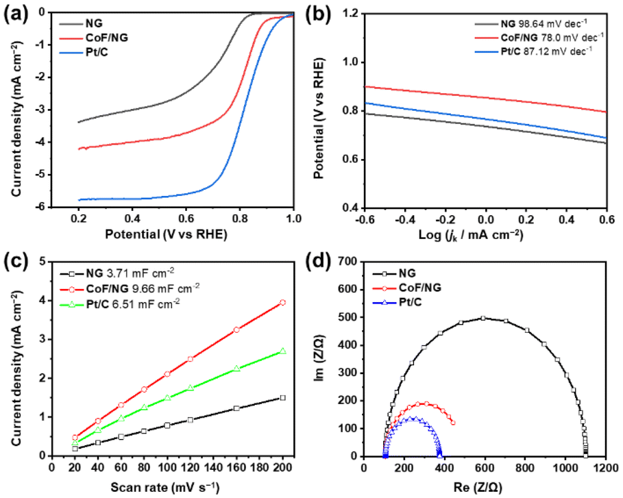 | ||
| Fig. 4 Electrochemical performance of NG, CoF/NG, and Pt/C. (a) LSV polarization curves, (b) Tafel slopes, (c) double-layer capacitance measurements to determine ECSA, and (d) EIS curves. | ||
| Sample | Onset potential (V) | Half-wave potential (V) | jL (mA cm−2) | R1 (Ω) | R2 (Ω) |
|---|---|---|---|---|---|
| NG | 0.85 | 0.70 | 3.38 | 106.3 | 1279 |
| CoF/NG | 0.91 | 0.80 | 4.22 | 106.0 | 441 |
| Pt/C | 0.99 | 0.82 | 5.77 | 106.0 | 381 |
As discussed above, atomically dispersed Co-containing species are attached to the surface of the NG. Because the N or O sites on the surface of NG can bind to Co atoms, Co–(N)graphene and Co–(O)graphene can act as ORR active species. To investigate the major active species, ReG and CoF/ReG samples were prepared as control samples. Because ReG was produced by refluxing aqueous G-O suspension without the addition of any other chemical reductants, no N species exist in the ReG. Subsequently, CoF/ReG would contain only Co–(O)graphene species without the contribution of Co–(N)graphene species.
Similar to the CoF/NG, SEM, TEM and XRD measurements of CoF/ReG support no formation of crystalline particles containing Co (Fig. S4 and S5†). As shown in EDX elemental mapping images, Co atoms are well-dispersed along the CoF/ReG sample (Fig. S6†).
XANES and EXAFS spectra of CoF/ReG are similar to those of CoF/NC (Fig. S7 and Table S3†). These features suggest that no Co-based crystalline particles are generated and Co-based species with an oxidation state of +2 are well-dispersed in the molecular level on the surface of ReG.13,23
Interestingly, the electrocatalytic activity of the control CoF/ReG is significantly lower than that of CoF/NG. As shown in Fig. S8 and Table S4,† the onset and half-wave potentials and limited current densities of the CoF/ReG are much lower than those of the CoF/NG. These features suggest that the dominant active species in CoF/NG are different from that in CoF/ReG, which excludes the Co–(O)graphene structure from the major active species of the CoF/NG system. This control experiment suggests that Co–(N)graphene could be the active species for electrocatalytic ORR in CoF/NG.
Electrocatalytic stability is one of important factors for the industrial application of ORR catalysts. It is important to determine the stability of ORR catalysts under exposure to methanol in direct methanol fuel cells. While the low tolerance for methanol is a significant limitation of Pt/C, CoF/NG shows stable electrocatalytic performance without a current drop upon the addition of methanol (Fig. S9†), confirming the good tolerance of CoF/NG to methanol poisoning. To check long-term stability of electrocatalysts during electrochemical cycles, LSV curves at the initial and 10000th cycles and i–t curves were obtained for the CoF/NG sample. Fig. S10† shows that the onset and half-wave potentials and limited current density of CoF/NG decrease significantly after 10000 cycles. The i–t curve of CoF/NG, which was measured at 0.87 V, shows a mediocre stability with the current-decrease by 7.9% after 20000 s (Fig. S11†). To monitor morphological changes of CoF/NG during the electrochemical ORR measurements, the CoF/NG samples were obtained from the electrodes after ORR measurements (samples are denoted as CoF/NG-after-cycle). Noticeably, the STEM image of the CoF/NG-after-cycle sample shows the formation of nanoparticles (Fig. S12†). This morphological change indicates some of Co-containing species in CoF/NG aggregates during the electrochemical ORR measurements.
These data compare to previous literature reporting Co-based SACs containing electron-donating groups.13,15,32 Those electrocatalysts show better long-term cycling durability than CoF/NG and no aggregated particles were observed from after-cycle samples. All these experiments support that the incorporation of Co-based organometallic species containing electron-withdrawing groups around the metal center onto graphene-based networks improves the electrocatalytic ORR performance. However, the presence of electron-withdrawing groups around the Co-based active species could diminish the electrocatalytic stability during ORR measurements.
Conclusions
In this work, the effect of electron-withdrawing groups on the electrocatalytic ORR properties of atomically dispersed Co-based species was investigated. Through the synthesis of CoF/NG, Co-based organometallic species (CoF) were successfully immobilized onto the NG surface using a low-temperature wet process. Characterization techniques including XPS, XRD, TEM, and XANES confirmed the molecular dispersion of Co-based species on the NG surface without the formation of crystalline Co-based particles.Electrochemical measurements revealed that CoF/NG exhibited significantly enhanced ORR activity compared to NG, with the onset and half-wave potentials of 0.91 and 0.80 V, respectively. The CoF/NG catalyst showed good selectivity towards the four-electron pathway of the ORR and an electron transfer number of 3.72. Control experiments using CoF/ReG, where no N species were present, suggested that Co–(N)graphene species were likely the active sites responsible for the enhanced ORR activity observed in CoF/NG.
Our findings suggest that the incorporation of Co-based species on graphene-based networks at the molecular level can generate efficient ORR electrocatalysts. This work provides valuable insights for the rational design of efficient and cost-effective ORR catalysts based on single-atom catalysts.
Author contributions
Sungjin Park supervised this study. Yunseok Shin performed synthesis and characterization of materials and electrochemical measurements. Sunggu Park performed synthesis and characterization of materials. Hanbi Jang performed synthesis. Gogyun Shin and Dongha Shin performed Raman spectroscopy. Sungjin Park, Yunseok Shin, and Sunggu Park wrote the manuscript and contributed to revising the manuscript.Data availability
The data supporting this article have been included as part of the ESI.†Conflicts of interest
There are no conflicts to declare.Acknowledgements
This work was supported by the National Research Foundation of Korea (NRF) grants funded by the Korean government (MEST) (RS-2024-00335043). We thank the Busan Center at the Korea Basic Science Institute (KBSI) for XPS analysis. X-ray absorption spectroscopy (XAS) measurements were conducted using beamline 10C at the Pohang Accelerator Laboratory (PAL, Pohang, South Korea).References
- T.-G. Vo, J. Gao and Y. Liu, Adv. Funct. Mater., 2024, 2314282 CrossRef CAS.
- H. Cao, T. Wei, Q. Liu, S. Zhang, Y. Qin, H. Wang, J. Luo and X. Liu, ChemCatChem, 2023, 15, e202201615 CrossRef CAS.
- D. S. Baek and S. H. Joo, Bull. Korean Chem. Soc., 2022, 43, 1156–1168 CrossRef CAS.
- M. D. Bhatt and J. Y. Lee, Energy Fuels, 2020, 34, 6634–6695 CrossRef CAS.
- P. Viswanathan, D. Lee, S. Manivannan, T. Yim and K. Kim, Bull. Korean Chem. Soc., 2022, 43, 396–401 CrossRef CAS.
- S. Ahmed, H.-R. Rim, H.-J. Sun, H.-K. Lee, J. Shim and G. Park, Bull. Korean Chem. Soc., 2022, 43, 745–749 CrossRef CAS.
- F. Jiang, Y. Li and Y. Pan, Adv. Mater., 2024, 36, 2306309 CrossRef CAS PubMed.
- L. Zhang, X. Zhao, Z. Yuan, M. Wu and H. Zhou, J. Mater. Chem. A, 2021, 9, 3855–3879 RSC.
- S. K. Singh, K. Takeyasu and J. Nakamura, Adv. Mater., 2019, 31, 1804297 CrossRef PubMed.
- S. Zaman, L. Huang, A. I. Douka, H. Yang, B. You and B. Y. Xia, Angew. Chem., 2021, 133, 17976–17996 CrossRef.
- W. Wan, Y. Zhao, J. Meng, C. S. Allen, Y. Zhou and G. R. Patzke, Small, 2024, 20, 2304663 CrossRef CAS PubMed.
- Y. Yu, Z. Zhu and H. Huang, Adv. Mater., 2024, 2311148 CrossRef CAS PubMed.
- Y. Shin, Y. Lee, C. Jo, Y.-H. Kim and S. Park, EcoEnergy, 2024, 2, 154–168 CrossRef.
- S. Ajmal, Y. Zhao, G. Yasin, F. O. Boakye, M. Tabish, M. M. Alam, A. G. Al-Sehemi and W. Zhao, ChemCatChem, 2024, e202301392 CrossRef CAS.
- J. Han, Y. J. Sa, Y. Shim, M. Choi, N. Park, S. H. Joo and S. Park, Angew. Chem., Int. Ed., 2015, 54, 12622–12626 CrossRef CAS PubMed.
- S. Kim, D. Jang, J. Lim, J. Oh, S. O. Kim and S. Park, ChemSusChem, 2017, 10, 3473–3481 CrossRef CAS PubMed.
- R. Zhou, Y. Zheng, M. Jaroniec and S.-Z. Qiao, ACS Catal., 2016, 6, 4720–4728 CrossRef CAS.
- K. Jiang, S. Back, A. J. Akey, C. Xia, Y. Hu, W. Liang, D. Schaak, E. Stavitski, J. K. Nørskov, S. Siahrostami and H. Wang, Nat. Commun., 2019, 10, 3997 CrossRef PubMed.
- Y. Shin and S. Park, Carbon Lett., 2021, 31, 887–893 CrossRef.
- Y. Shin, S. Lee, S. Park, D. Jang, D. Lim, G. Park, S. Seok and S. Park, ChemistrySelect, 2018, 3, 12690–12695 CrossRef CAS.
- M. Choi, S. Lee, D. Jang and S. Park, Carbon Lett., 2022, 32, 885–892 CrossRef.
- S. Lee, E. Y. Shin, D. Jang, S. Choi, H. Park, J. Kim and S. Park, Bull. Korean Chem. Soc., 2022, 43, 1124–1129 CrossRef CAS.
- B. Gupta, N. Kumar, K. Panda, V. Kanan, S. Joshi and I. Visoly-Fisher, Sci. Rep., 2017, 7, 1–14 CrossRef CAS PubMed.
- T. Wang, Q. Zhang, K. Lian, G. Qi, Q. Liu, L. Feng, G. Hu, J. Luo and X. Liu, J. Colloid Interface Sci., 2023, 655, 176–186 CrossRef PubMed.
- W. Zou, J. Zhang, M. Liu, J. Li, Z. Ren, W. Zhao, Y. Zhang, Y. Shen and Y. Tang, Adv. Mater., 2024, 2400537 CrossRef CAS PubMed.
- Y. Shin and S. Park, Carbon Lett., 2022, 32, 885–892 CrossRef.
- Y. Tang, L. Dong, S. Mao, H. Gu, T. Malkoske and B. Chen, ACS Appl. Energy Mater., 2018, 1, 2698–2708 CrossRef CAS.
- T. Wang, S. Gao, T. Wei, Y. Qin, S. Zhang, J. Ding, Q. Liu, J. Luo and X. Liu, Chem. – Eur. J., 2023, 29, e202204034 CrossRef CAS PubMed.
- C. H. M. van Oversteeg, H. Q. Doan, F. M. F. de Groot and T. Cuk, Chem. Soc. Rev., 2017, 46, 102–125 RSC.
- A. B. Jorge, R. Jervis, A. P. Periasamy, M. Qiao, J. Feng, L. N. Tran and M.-M. Titirici, Adv. Energy Mater., 2020, 10, 1902494 CrossRef CAS.
- J. A. Trindell, Z. Duan, G. Henkelman and R. M. Crooks, Chem. Rev., 2020, 120, 814–850 CrossRef CAS PubMed.
- D. Jang, Y. Lee, Y. Shin, S. Park, C. Jo, Y.-H. Kim and S. Park, Appl. Catal., B, 2020, 263, 1187337 CrossRef.
Footnotes |
| † Electronic supplementary information (ESI) available. See DOI: https://doi.org/10.1039/d4nr01635a |
| ‡ These authors equally contributed to this work. |
| This journal is © The Royal Society of Chemistry 2024 |