Unveiling the electronic properties of metal-free and undoped covalent organic framework as a semiconductor†
Kushagra
Yadav
ab,
Praveen K.
Budakoti
 c and
S. R.
Dhakate
 *ab
*ab
aAdvanced Carbon Products and Metrology, CSIR-NPL, Dr K.S. Krishnan Marg, New Delhi 110012, India
bAcademy of Scientific & Innovative Research (AcSIR), Ghaziabad, Uttar Pradesh 201002, India
cInstitute of Physical and Theoretical Chemistry, Goethe University Frankfurt, Max-von-Laue Straße 7, 60438, Frankfurt am Main, Germany. E-mail: dhakate@nplindia.org
First published on 14th November 2023
Abstract
Covalent organic frameworks (COFs) are an emerging category of semiconducting material. In the present investigation, a conjugated covalent organic framework (PPDA–TFPT–COF) composed of p-phenylenediamine (PPDA) and 2,4,6-tris-(p-formylphenoxy)1,3,5-triazine (TFPT) was designed and developed via Schiff-base reaction under solvothermal conditions. The morphology and electronic properties of PPDA–TFPT–COF were analyzed through various characterization techniques. The XPS studies reveal that imine linkages (C![[double bond, length as m-dash]](https://www.rsc.org/images/entities/char_e001.gif) N) are formed during the reaction consisting of N-rich species possessing the property of reversibility. The semiconducting nature of PPDA–TFPT–COF is verified via the measurement of electrical conductivity (10−6–10−5 S cm−1) by the four-probe measurement method. The band gap of the developed polymer is in the range of 3.2–3.4 eV, measured by UV spectroscopy, ultraviolet photoelectron spectroscopy (UPS) and cyclic voltammetry (CV), and theoretically validated by density functional theory (DFT) calculations of the ring monomer unit. Also, DFT calculation revealed that PPDA–TFPT–COF possesses π–π conjugation throughout the polymeric ring. This study brings out the fact that by controlling the moieties, it is possible to develop a semiconducting covalent organic framework within a short duration time-period without metal or charge doping.
N) are formed during the reaction consisting of N-rich species possessing the property of reversibility. The semiconducting nature of PPDA–TFPT–COF is verified via the measurement of electrical conductivity (10−6–10−5 S cm−1) by the four-probe measurement method. The band gap of the developed polymer is in the range of 3.2–3.4 eV, measured by UV spectroscopy, ultraviolet photoelectron spectroscopy (UPS) and cyclic voltammetry (CV), and theoretically validated by density functional theory (DFT) calculations of the ring monomer unit. Also, DFT calculation revealed that PPDA–TFPT–COF possesses π–π conjugation throughout the polymeric ring. This study brings out the fact that by controlling the moieties, it is possible to develop a semiconducting covalent organic framework within a short duration time-period without metal or charge doping.
Introduction
Covalent organic frameworks (COFs) have emerged as promising 2D materials for organic electronics due to their immense structural diversity and electronic properties tunable by chemical design. COFs are highly cross-linked polymeric materials that range from amorphous to semi-crystalline in nature and are held together by strong covalent linkages.1,2 The COFs are conventionally made up of organic building blocks comprising light elements such as carbon and nitrogen, which are obtained in situ during the synthesis process.3 Recently, triazine-based COFs have been introduced consisting of intrinsic micro-porosity4 along with conjugation throughout the polymer. Compared to the traditional porous materials such as zeolites and porous carbon,5 they have integrated insolubility, flexibility, low density, chemical, and thermal stability.6 COFs are typically processed by Schiff's base formation and C–C coupling.7–9 Schiff-base chemistry, also known as dynamic imine chemistry, is one of the most used processes for building covalent organic frameworks.9In comparison to other materials, COFs with conjugated nitrogen-rich active sites provide electron transport throughout the polymer. They possess extremely good physicochemical properties,9 and as a consequence, they can be used in a variety of promising applications such as sensors,10 solar energy, optoelectronic devices, clean energy,11–15 superconductivity,16,17 and semiconductors,18–20 V. Laxmi et al. reported a Pd-catalyzed (aza) triangulene-based covalent organic framework named as TANG-COF which shows paramagnetic behaviour with Eg ≈ 1.2 eV.21 R. Wang et al. reported an n-type benzibisthiadiazole-based covalent organic framework with a narrow bandgap.22 COFs that are entirely π-conjugated and chemically stable are highly advantageous in the semiconducting field. Such polymers with highly ordered chain alignment could be used to solve semiconducting polymer technology problems.23 The solvothermal approach is commonly employed to synthesize COFs since it does not necessitate particularly challenging experimental reaction conditions.24
The electrical conductivity of organic compounds nearly similar to metals was reported at the beginning of the twentieth century, and with the development of charge transfer complexes and conjugated polymers in the second half of the century, could be favourable in reality.25 While most organic compounds are insulators, numerous approaches are adopted for constructing semiconductors, and superconductors with organic building blocks.26,27 Electrical conductivity in COFs is primarily determined by in-plane extended π–π conjugation and out-of-plane stacking across the polymer.28
In the past few years, researchers have paid more interest in the establishment of metal-linked or n- and p-type doped COFs for several applications such as photocatalytic activities, and29 catalytic activities. Subodh et al. reported a silver nanoparticle-immobilized triazine-based COF by using the TAPT and TFPT precursors for hydrogenation of nitroaromatics with intriguing catalytic activity30 and a few other researchers also developed triazine-based COF synthesis in seven days using metals for various applications. Usually triazine-based COFs are synthesized in seven days, but in the present contribution, an undoped, metal-free, and fully π–π conjugated p-phenylenediamine and 2,4,6-tris-(p-formylphenoxy)1,3,5-triazine-based polymeric COF has been developed within three days using distinct synthetic methodology for acquiring appropriate semiconducting properties with the theoretical validations through DFT studies. The developed COF was characterized by various spectroscopic techniques. The experimental findings suggest that the band gap is in the range of semiconducting materials, and it is theoretically validated using DFT calculations on the ring monomer of PPDA–TFPT–COF, which is supported by theoretical calculations.31–33 It also reveals complete conjugation throughout the polymer ring. To the best of our knowledge, we are reporting for the first time the complete exploration of the semiconducting properties through experimental validation along with DFT studies at the electronic molecular orbital level of a metal-free and undoped triazine-based COF.
Results and discussion
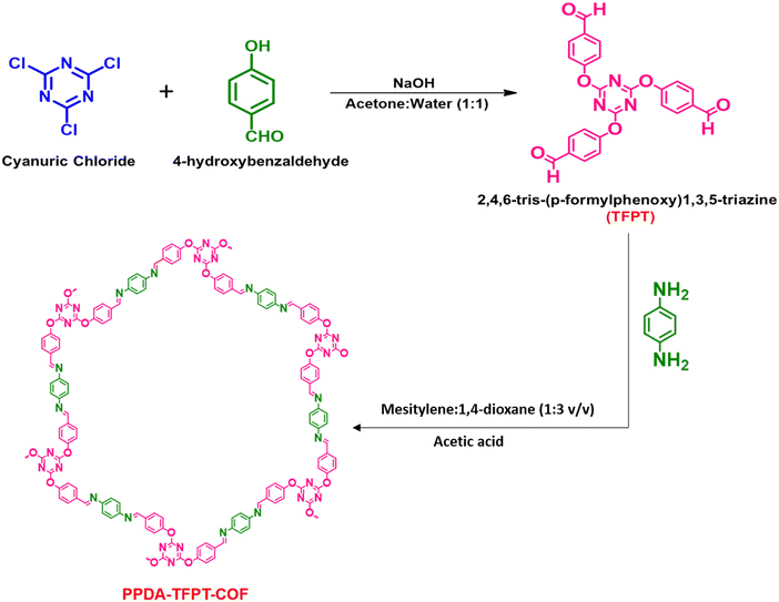
A simple, cost-effective, and co-effective one-pot synthetic procedure for the development of micro-spherical PPDA–TFPT–COF has been presented. This procedure involves a nucleophilic addition reaction between p-phenylenediamine (PPDA) and C3 symmetric triazine analog (N/O – rich) 2,4,6-tris-(p-formylphenoxy)1,3,5-triazine (TFPT) precursors, leading to the formation of an imine-linked product. Subsequently, a Schiff-base reaction is carried out in the presence of mesitylene as a solvent and 1,4-dioxane as a hard base in a 1![[thin space (1/6-em)]](https://www.rsc.org/images/entities/char_2009.gif) :
:![[thin space (1/6-em)]](https://www.rsc.org/images/entities/char_2009.gif) 3 v/v ratio under solvothermal conditions (Scheme 1). This procedure provides a simple and efficient method for the synthesis of conjugated triazine-based COFs. The precursor 2,4,6-tris-(p-formylphenoxy)1,3,5-triazine (TFPT) was synthesized prior to the one-pot synthetic procedure for the development of the conjugated covalent organic framework. The synthesis of TFPT has been accomplished through a nucleophilic aromatic substitution SNAr reaction between cyanuric chloride and p-hydroxybenzaldehyde in the presence of NaOH as a strong base. A solvent system composed of 1
3 v/v ratio under solvothermal conditions (Scheme 1). This procedure provides a simple and efficient method for the synthesis of conjugated triazine-based COFs. The precursor 2,4,6-tris-(p-formylphenoxy)1,3,5-triazine (TFPT) was synthesized prior to the one-pot synthetic procedure for the development of the conjugated covalent organic framework. The synthesis of TFPT has been accomplished through a nucleophilic aromatic substitution SNAr reaction between cyanuric chloride and p-hydroxybenzaldehyde in the presence of NaOH as a strong base. A solvent system composed of 1![[thin space (1/6-em)]](https://www.rsc.org/images/entities/char_2009.gif) :
:![[thin space (1/6-em)]](https://www.rsc.org/images/entities/char_2009.gif) 1 v/v acetone and water was utilized during the reaction (Scheme 1). The successful preparation of TFPT was determined via1H and 13C NMR spectroscopy (Fig. S1 and S2, ESI†). Scheme 1 provides a schematic illustration of the steps that were used to synthesize PPDA–TFPT–COF.
1 v/v acetone and water was utilized during the reaction (Scheme 1). The successful preparation of TFPT was determined via1H and 13C NMR spectroscopy (Fig. S1 and S2, ESI†). Scheme 1 provides a schematic illustration of the steps that were used to synthesize PPDA–TFPT–COF.
The synthesis of PPDA–TFPT–COF was confirmed by several routine-to-sophisticated techniques. Initially, Fourier transform infrared (FTIR) spectroscopy was used to evaluate the successful preparation and structural bonding features of PPDA–TFPT–COF. Fig. 1(a) depicts the FTIR spectra of TFPT and PPDA precursors along with PPDA–TFPT–COF. On comparison, the disappearance of the peaks from PPDA–TFPT–COF at 1697 and 3000–3371 cm−1 belonging to –C![[double bond, length as m-dash]](https://www.rsc.org/images/entities/char_e001.gif) O in TFPT and –N–H in PPDA, respectively, confirmed the effective utilization of the precursors. Furthermore, new peaks appeared in the FTIR spectra of PPDA–TFPT–COF around 1668 cm−1 belonging to the C
O in TFPT and –N–H in PPDA, respectively, confirmed the effective utilization of the precursors. Furthermore, new peaks appeared in the FTIR spectra of PPDA–TFPT–COF around 1668 cm−1 belonging to the C![[double bond, length as m-dash]](https://www.rsc.org/images/entities/char_e001.gif) C stretching mode and 1589 cm−1 associated with imine C
C stretching mode and 1589 cm−1 associated with imine C![[double bond, length as m-dash]](https://www.rsc.org/images/entities/char_e001.gif) N stretching, the peaks at 1520 and 1456 cm−1 can be linked to triazine rings, the peak at 1367 cm−1 is attributed to C–N stretching, the peak at 1209 cm−1 represents C–O–C bonds and 810 cm−1 is of the breathing modes of triazine bonds. A bending vibrational mode of the imine was observed at 1681 cm−1 and another at 1206 cm−1,34–36 providing evidence of the presence of the imine linkage in the polymer.
N stretching, the peaks at 1520 and 1456 cm−1 can be linked to triazine rings, the peak at 1367 cm−1 is attributed to C–N stretching, the peak at 1209 cm−1 represents C–O–C bonds and 810 cm−1 is of the breathing modes of triazine bonds. A bending vibrational mode of the imine was observed at 1681 cm−1 and another at 1206 cm−1,34–36 providing evidence of the presence of the imine linkage in the polymer.
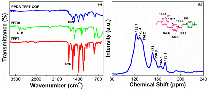 | ||
| Fig. 1 (a) FTIR spectra of TFPT, PPDA, and PPDA–TFPT–COF. (b) 13C-CPMAS NMR spectra of PPDA–TFPT–COF. | ||
PPDA–TFPT–COF was characterized by cross-polarization magic angle spinning 13C-CPMAS NMR to elucidate its structural attributes. In the 13C-CPMAS NMR spectrum, seven prominent peaks at 122.7, 128.4, 134.2, 151, 156.8, 165.1, and 173.1 ppm were observed (Fig. 1(b)). The peaks at 173.1, 156.8, 151, and 134.2 ppm corresponded to the quaternary carbon atoms of the triazine ring linked to the –O atoms, the aromatic ring from the TFPT precursor linked to the –O atoms, the aromatic ring from the PPDA precursor linked to the –N atoms of the imine bond and the aromatic ring from the TFPT precursor linked to the –C atoms of the imine bond, respectively. Furthermore, the carbon atom of the newly formed imine (C![[double bond, length as m-dash]](https://www.rsc.org/images/entities/char_e001.gif) N) bond was confirmed by the peak at 165.1 ppm. Finally, the peaks at 128.4 and 122.7 belong to the non-substituted carbon atoms of the aromatic ring from the TFPT precursor. Thus, the NMR peaks established a direct correlation with the proposed structure of PPDA–TFPT–COF and confirmed its synthesis.37
N) bond was confirmed by the peak at 165.1 ppm. Finally, the peaks at 128.4 and 122.7 belong to the non-substituted carbon atoms of the aromatic ring from the TFPT precursor. Thus, the NMR peaks established a direct correlation with the proposed structure of PPDA–TFPT–COF and confirmed its synthesis.37
To assess the chemical composition and combination states of the as-prepared samples in detail, X-ray photoelectron spectroscopy (XPS) is carried out and compared as shown in Fig. 2. The XPS survey spectra of PPDA–TFPT–COF validate the existence of C, N, and O on the surface, implying the successful synthesis of the COF. The C 1s spectral analysis, represented in Fig. 2, displays five distinguishable peaks at 284.3 eV, 284.8 eV, 285.3 eV, 288.9 eV, and 286.5 eV. These peaks correspond to the presence of C![[double bond, length as m-dash]](https://www.rsc.org/images/entities/char_e001.gif) C, C–H, C–C, C–O, and C–N functional groups, respectively. The highest intensity peak, located at 284.3 eV, can be attributed to the strong sp2 bond formation in the polymeric ring monomer, leading to the high intensity of the C
C, C–H, C–C, C–O, and C–N functional groups, respectively. The highest intensity peak, located at 284.3 eV, can be attributed to the strong sp2 bond formation in the polymeric ring monomer, leading to the high intensity of the C![[double bond, length as m-dash]](https://www.rsc.org/images/entities/char_e001.gif) C peaks. This observation supports the presence of π–π conjugation in the polymeric ring monomer.38 The N 1s spectrum, after deconvolution, reveals two distinct peaks at 398.6 eV and 399.4 eV. This finding confirms the presence of an imine bond and a triazine ring in the polymer.30 The N 1s spectrum shows a strong shift, which is attributed to the strong intramolecular interaction between the core nitrogen atom of the triazine unit. Two peaks of O 1s at binding energies 532.1 eV and 534.1 eV are observed in the O 1s spectrum. These peaks corresponded to C–O–C and C–O linkages, respectively. These linkages can be ascribed to adsorbed oxygen, oxygen defects, and lattice oxygen within the material.39 The O 1s spectrum exhibits the absence of a carbonyl peak, indicating that the carbonyl group has undergone complete conversion into an imine. This transformation is evident in the N 1s spectrum where the presence of the imine bond is observed. The same phenomenon of C
C peaks. This observation supports the presence of π–π conjugation in the polymeric ring monomer.38 The N 1s spectrum, after deconvolution, reveals two distinct peaks at 398.6 eV and 399.4 eV. This finding confirms the presence of an imine bond and a triazine ring in the polymer.30 The N 1s spectrum shows a strong shift, which is attributed to the strong intramolecular interaction between the core nitrogen atom of the triazine unit. Two peaks of O 1s at binding energies 532.1 eV and 534.1 eV are observed in the O 1s spectrum. These peaks corresponded to C–O–C and C–O linkages, respectively. These linkages can be ascribed to adsorbed oxygen, oxygen defects, and lattice oxygen within the material.39 The O 1s spectrum exhibits the absence of a carbonyl peak, indicating that the carbonyl group has undergone complete conversion into an imine. This transformation is evident in the N 1s spectrum where the presence of the imine bond is observed. The same phenomenon of C![[double bond, length as m-dash]](https://www.rsc.org/images/entities/char_e001.gif) O conversion into C
O conversion into C![[double bond, length as m-dash]](https://www.rsc.org/images/entities/char_e001.gif) N can be confirmed as the absence of a carbonyl peak in the C 1s spectrum. This observation reflects the fact that the C
N can be confirmed as the absence of a carbonyl peak in the C 1s spectrum. This observation reflects the fact that the C![[double bond, length as m-dash]](https://www.rsc.org/images/entities/char_e001.gif) N active sites have undergone ion coordination.
N active sites have undergone ion coordination.
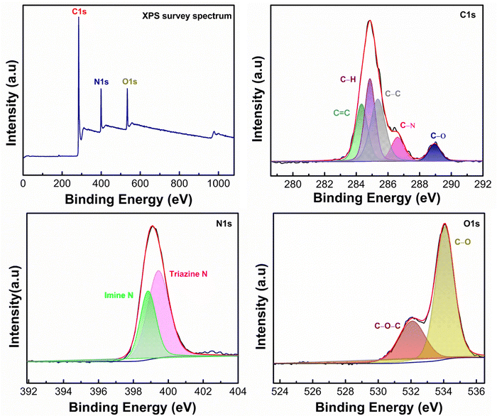 | ||
| Fig. 2 Complete XPS spectrum of the synthesized PPDA–TFPT–COF with deconvoluted C 1s, N 1s, and O 1s spectra. | ||
The surface area and porosity of PPDA–TFPT–COF were measured through a Brunauer–Emmett–Teller (BET) analyzer using nitrogen adsorption–desorption (Fig. 3(a)). The N2 adsorption/desorption isotherm determines bulk and textural properties like the porosity and surface area of the COF. The elevated high thermal stability, as quantified in thermogravimetric analysis (TGA, Section S3, ESI†), facilitates the determination of the degassing temperature. The material was subjected to degassing at approximately 250 °C, followed by the isotherm experiment at a temperature of 77 K. According to the IUPAC classification, the type IV isotherm with a H4 hysteresis loop demonstrates the presence of mesoporosity of PPDA–TFPT–COF. The BET surface area of PPDA–TFPT–COF is 77.72 m2 g−1. The desorption pore volume and pore diameter Dv(d) of PPDA–TFPT–COF were determined by the Barrett–Joyner–Halenda (BJH) method and it is 0.168 cm3 g−1 and 4.27 nm, respectively (inset, Fig. 3(a)). The comparatively low surface area of PPDA–TFPT–COF is due to the random displacement of the polymeric chains in the material.40 The thermal stability of PPDA–TFPT–COF was analyzed by thermogravimetric analysis (TGA), and the TGA data reveals that there is small weight loss up to 100 C and ∼9% weight loss in between temperatures 100–300 °C. The major weight loss of ∼50.8% from 301–900 °C occurs due to the complete decomposition of the organic polymer and residues. The total weight loss is about ∼63%, the remaining residue around 37% is carbon and more information is provided in Section S3 (ESI†).
 | ||
| Fig. 3 (a) Nitrogen adsorption–desorption isotherm of PPDA–TFPT–COF. (b) FESEM image of PPDA–TFPT–COF. (c) HR-TEM image of PPDA–TFPT–COF. | ||
The morphological attributes of PPDA–TFPT–COF were recorded by field emission scanning electron microscopy (FESEM) and high-resolution transmission electron microscopy (HR-TEM) (Fig. 3(b)–(c)). The FESEM image of PPDA–TFPT–COF demonstrates a self-assembly of partially spherical agglomerates with irregular morphology (Fig. 3(b)). As seen, the COF can self-assemble into large agglomerated spherical or hollow-tubular morphologies.41 Observations indicate that COFs have the ability to self-assemble into spherical or hollow-tubular morphologies. This phenomenon is believed to stem from the edge-to-edge connection between flexible C3-symmetric monomers via imine-linkage, leading to the formation of a curved surface, which promotes cross-linkage with each other leading to the formation of a spherical morphology. A noteworthy observation was encountered during the analysis: the PPDA–TFPT–COF retained its spherical morphology, which was distinct from previously known polymeric morphologies. This stability was maintained even under the high-resolution imaging conditions of an electron microscope. A transmission electron microscopy (TEM) image (inset, Fig. 3(c)) of the PPDA–TFPT–COF shows a quasi-spherical morphology having irregularly shaped particles with a dark contrast at the center of the sphere and bright contrast at the spherical wall. This represents a distinctive reflection of the spherical structure and serves as a visual representation of the unique morphological features of the polymer. Both FESEM and TEM images display similar microstructures. Alternately uniform dark and bright worm-like-structures in HR-TEM (Fig. 3(c)) reveal the porous nature of the synthesized COF.
The Fermi energy level (EFermi) and valence band maximum (VBM) of the PPDA–TFPT–COF were determined through ultraviolet photoelectron spectroscopy (UPS) analysis. The full scan UPS spectra of PPDA–TFPT–COF (Fig. 4(a)) were used to calculate the cut-off edge energy (Ecutoff) and Fermi edge energy (EFermi), which were found to be 15.78 and 1.05 eV, respectively (Fig. 4(b)).39 Based on the values of the cut-off edge energy (Ecutoff) and Fermi energy level (EFermi), the valence band maximum (VBM) of the PPDA–TFPT–COF was calculated to be 6.48 eV. Furthermore, the depth of the Fermi level was determined to be 5.48 eV. In conjunction with the results obtained from the band gap energy analysis (Fig. S5, ESI†), the conduction band minimum (CBM) of the PPDA–TFPT–COF was calculated to be 9.73 eV. Additionally, the bandgap (Eg), highest occupied molecular orbital (HOMO) level (EV), and lowest unoccupied molecular orbital (LUMO) level (EC) of the PPDA–TFPT–COF were obtained through electrochemical analysis using cyclic voltammetry. The results, presented in Fig. 5, indicate that the bandgap, HOMO, and LUMO are found to be 3.25, −5.5, and −2.3 eV, respectively.42 All calculated band gap values through UV, UPS, and CV are comparable with the theoretical band gap value through density functional theory, which is almost equal to 3.12–3.4 eV.
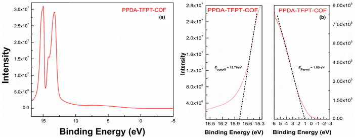 | ||
| Fig. 4 (a) Full scan UPS spectra, and (b) cutoff edge (left) and Fermi edge (right) of PPDA–TFPT–COF. | ||
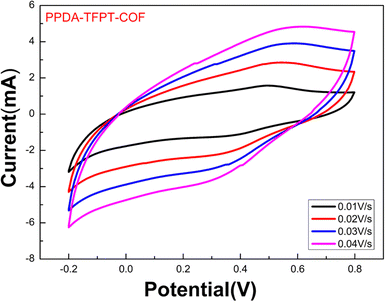 | ||
| Fig. 5 Cyclic voltammetry measurement for the bandgap (Eg), HOMO (EV), and LUMO (EC) of PPDA–TFPT–COF. | ||
This study aimed to determine the band-edge energies of PPDA–TFPT–COF, which was grown in situ on a platinum wire.21,42 To accomplish this, a cyclic voltammetry (CV) measurement was performed on the material (Fig. 5). The results of the CV measurement showed that the oxidation of PPDA–TFPT–COF was observed as a quasi-reversible wave with an onset (Eonset(ox)) potential of 0.75 V vs. Ag/AgCl. Additionally, an irreversible reduction with an onset (Eonset(red)) potential of −2.50 V was also observed. Based on the onset potentials, the HOMO (highest occupied molecular orbital) (Ev) and LUMO (lowest unoccupied molecular orbital) (Ec) levels of the COF were determined to be −5.55 and −2.3 eV, respectively. Using these values; the electrochemical band gap (Eg) of PPDA–TFPT–COF was found to be 3.25 eV. The calculated band gap through CV measurement was found to be in good agreement with UV, UPS, and DFT calculations.
The HOMO–LUMO band gap was determined using the following equation:
| −ELUMO = Eonset(red) + 4.8 eV |
| −EHOMO = Eonset(ox) + 4.8 eV |
Based on the equations and graph obtained from the cyclic voltammetry measurement, the conduction band (Ec), valence band (EV), and electrochemical band gap (Eg) of PPDA–TFPT–COF are as follows:
| ELUMO = EC = −2.3 eV |
| EHOMO = EV = −5.55 eV |
| Eg = 3.25 eV |
Computational analysis
This section reports the semiconducting characteristics of PPDA–TFPT–COF molecules and conducts an excited state investigation of the molecule using density functional theory (DFT). The polymeric PPDA–TFPT–COF is shown in its entirety in Scheme 1; by truncating the polymeric chains and adding a H-atom, it forms the ring monomer of the PPDA–TFPT–COF compound.The electrostatic potential in the PPDA–TFPT–COF ring monomer is depicted in Fig. 6. The positive and negative charge distribution of the triazine corner is substantially higher than that of the benzene-conjugated sides, indicating a higher possibility of finding holes and electrons.
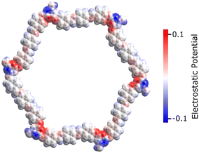 | ||
| Fig. 6 Electrostatic potential of the PPDA–TFPT–COF monomer at the van der Waals surface for isovalues (−0.1 to 0.1) in the physical units used by Avogadro software.43 The negative and positive charge distributions on the monomer unit are represented by the blue and red color maps, respectively. | ||
Time-dependent density functional theory (TD-DFT) calculations are used to comprehend the nature of singlet electronic excitations in the PPDA–TFPT–COF ring monomer. The Gaussian16 package44 was used to implement the time-dependent density functional theory (TD-DFT) approach and perform all electronic structure calculations. It is challenging to use DFT to optimize the PPDA–TFPT–COF structure due to there being 276 atoms in the ring monomer unit. To address this problem, the ground state geometry was optimized using the classical universal force field (UFF) in the Avogadro package.43 UFF is a Lennard-Jones style force field and capable of dealing with most structural features across the periodic table. Excited state calculations were performed using TD-DFT with the hybrid B3LYP functional45 and 6-31G* basis set. B3LYP is a hybrid functional which uses approximations to the exchange–correlation energy functional in DFT. The excited state analysis of the PPDA–TFPT–COF ring monomer is shown in Table 1. It provides the results for the first 3 excited singlet states and information about the major molecular orbital (MO) changes for the excited states. More information is included in the ESI† regarding the electronic structure calculations. The first excited state (S1) has an excitation energy of 3.0 eV followed by the two degenerated states (S2 and S3) at 3.1 eV. S1 is the dark state (zero oscillator strength) and S2 and S3 which are degenerate are the first bright states. The higher states S4, S5, S6, and S7 are also dark states. S8 and S9 (Table S1, ESI†) are the second highest degenerated bright states whereas S10 is again a dark state.
| State | Excitation energy (eV) | Oscillator strength | Major MO changes |
|---|---|---|---|
| S1 | 3.0 | 0.0 | HOMO → LUMO |
| HOMO−1 → LUMO+2 | |||
| HOMO−2 → LUMO+1 | |||
| S2 | 3.1 | 6.99 | HOMO−1 → LUMO |
| HOMO → LUMO+1 | |||
| S3 | 3.1 | 6.99 | HOMO−2→ LUMO |
| HOMO → LUMO+2 |
The molecular orbital diagram of the PPDA–TFPT–COF monomer for the first three excitations is shown in Fig. 7 and explains the nature of charge delocalization over the whole molecule. HOMO and LUMO are delocalized over the whole monomer and the band gap which is the energy difference between the HOMO and LUMO is ∼3.4 eV and explains the semiconducting nature of the molecule. This result is also in line with the experimental UV-Vis spectra, UPS, and CV which shows the band gap around 3.2–3.4 eV. The theoretical UV-Vis spectra calculated using TD-DFT are depicted in Fig. S5 (ESI†) and match closely to experimental findings. The small difference between the experimental and theoretical values is the result of the truncation of the molecule to the monomer unit. Because of the highly symmetric nature of the monomer, it has degeneracy in the electronic excitations such that (S2, S3), (S4, S5) and (S8, S9) are degenerated electronic states and (HOMO−1, HOMO−2) and (LUMO+1, LUMO+2) are the degenerated molecular orbitals.
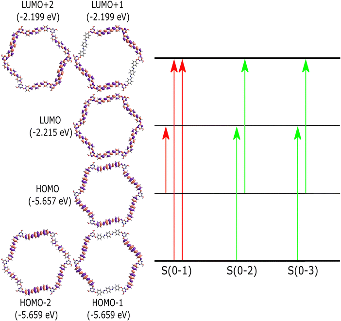 | ||
| Fig. 7 Molecular orbital diagram for the PPDA–TFPT–COF monomer unit. The first three singlet excitations (S(0–1), S(0–2), S(0–3)) are shown. The red transition shows the dark state and the green transition shows the bright electronic states (S2, S3). Table 1 provides more detail about the figure and the excited state transitions for the first three electronic states. | ||
On the other hand, the electrical properties of PPDA–TFPT–COF were measured using a four-probe method comprised of a KEITHLEY 6221 DC and AC source and KEITHLEY 2182A nanovoltmeter to find the nature of charge transport at room temperature. The electrical conductivity is in the range of 10−6–10−5 S cm−1 which shows the semiconducting nature of the PPDA–TFPT–COF.
Conclusions
This article reports the synthesis of an efficient, conjugated covalent organic framework using 2,4,6-tris-(p-formylphenoxy)1,3,5-triazine (TFPT) and p-phenylenediamine (PPDA) via a solvothermal process within a very short duration. During the course of the study, PPDA–TFPT–COF is discovered to possess semiconducting characteristics due to its fully-conjugated structure. DFT calculations are performed on a ring monomer of PPDA–TFPT–COF which revealed that the orbitals are substantially delocalized over the polymeric molecule while the electron and hole densities are highly localized on the triazine rings. The excited state studies explained that the states have a charge transfer nature. Finally, the band gap is in the range of 3.2–3.4 eV, calculated from ultraviolet spectroscopy, ultraviolet photoelectron spectroscopy, and cyclic voltammetry that are in agreement with the theoretical observations which explain the semiconducting nature of PPDA–TFPT–COF. The results of this investigation demonstrate the feasibility of developing semiconducting covalent organic frameworks without the need for metal or charge doping by carefully controlling the moieties involved in the synthesis. This finding highlights the potential for developing a high-performance, cost-effective semiconducting COF through judicious molecular design.Conflicts of interest
There are no conflicts to declare.Acknowledgements
The authors are thankful to Director, CSIR-NPL, for his kind permission to publish the results. The authors would also like to thank, Dr R. K. Seth, for providing TGA and BET analysis. The authors are also grateful to Dr Nawal Kishor for the XRD analysis.References
- Y. Zhang and S. N. Riduan, Chem. Soc. Rev., 2012, 41, 2083–2094 RSC.
- P. Puthiaraj, Y. R. Lee, S. Zhang and W. S. Ahn, J. Mater. Chem. A, 2016, 4, 16288–16311 RSC.
- D. M. Fischbach, G. Rhoades, C. Espy, F. Goldberg and B. J. Smith, Chem. Commun., 2019, 55, 3594–3597 RSC.
- N. B. Mc Keown and P. M. Budd, Chem. Soc. Rev., 2006, 35, 675–683 RSC.
- K. Chaudhary, K. Prakash and D. T. Masram, Appl. Surf. Sci., 2020, 509, 144902 CrossRef.
- P. Puthiaraj, S. M. Cho, Y. R. Lee and W. S. Ahn, J. Mater. Chem. A, 2015, 3, 6792–6797 RSC.
- S. Delpierre, B. Willocq, G. Manini, V. Lemaur, J. Goole, P. Gerbaux, J. Cornil, P. Dubois and J. M. Raquez, Chem. Mater., 2019, 31, 3736–3744 CrossRef CAS.
- D. Rodríguez-San-Miguel, C. Montoro and F. Zamora, Chem. Soc. Rev., 2020, 49, 2291–2302 RSC.
- J. L. Segura, M. J. Mancheño and F. Zamora, Chem. Soc. Rev., 2016, 45, 5635–5671 RSC.
- S. Dalapati, S. Jin, J. Gao, Y. Xu, A. Nagai and D. Jiang, J. Am. Chem. Soc., 2013, 135, 17310–17313 CrossRef CAS PubMed.
- S. Wan, J. Guo, J. Kim, H. Ihee and D. Jiang, Angew. Chem., Int. Ed., 2008, 47, 8826–8830 CrossRef CAS PubMed.
- E. L. Spitler and W. R. Dichtel, Nat. Chem., 2010, 2, 672–677 CrossRef CAS PubMed.
- H. Furukawa and O. M. Yaghi, J. Am. Chem. Soc., 2009, 131, 8875–8883 CrossRef CAS PubMed.
- P. Kuhn, M. Antonietti and A. Thomas, Angew. Chem., Int. Ed., 2008, 47, 3450–3453 CrossRef CAS PubMed.
- S. Y. Ding, J. Gao, Q. Wang, Y. Zhang, W. G. Song, C. Y. Su and W. Wang, J. Am. Chem. Soc., 2011, 133, 19816–19822 CrossRef CAS PubMed.
- M. G. Goesten and M. Amsler, ACS Mater. Lett., 2019, 1, 30–36 CrossRef CAS.
- H. Lyu, C. S. Diercks, C. Zhu and O. M. Yaghi, J. Am. Chem. Soc., 2019, 141, 6848–6852 CrossRef CAS PubMed.
- X. Ding, J. Guo, X. Feng, Y. Honsho, J. Guo, S. Seki, P. Maitarad, A. Saeki, S. Nagase and D. Jiang, Angew. Chem., Int. Ed., 2011, 50, 1289–1293 CrossRef CAS PubMed.
- M. Dogru and T. Bein, Chem. Commun., 2014, 50, 5531–5546 RSC.
- X. Guan, F. Chen, Q. Fang and S. Qiu, Chem. Soc. Rev., 2020, 49, 1357–1384 RSC.
- V. Lakshmi, C. H. Liu, M. Rajeswara Rao, Y. Chen, Y. Fang, A. Dadvand, E. Hamzehpoor, Y. Sakai-Otsuka, R. S. Stein and D. F. Perepichka, J. Am. Chem. Soc., 2020, 142, 2155–2160 CrossRef CAS PubMed.
- C. Wang, D. Yang and J. Guo, Chem. Mater., 2021, 33, 3566–3574 CrossRef.
- A. J. H. G. Yu, J. Gao, J. C. Hummelen and F. Wudi, Science, 1995, 270, 1–3 CrossRef.
- Y. Liu, W. Zhou, W. L. Teo, K. Wang, L. Zhang, Y. Zeng and Y. Zhao, Chem, 2020, 6, 3172–3202 CAS.
- M. L. Khidekel and E. I. Zhilyaeva, Synth. Met., 1981, 4, 1–34 CrossRef CAS.
- M. Souto and D. F. Perepichka, J. Mater. Chem. C, 2021, 9, 10668–10676 RSC.
- M. Bendikov, F. Wudl and D. F. Perepichka, Chem. Rev., 2004, 104, 4891–4945 CrossRef CAS PubMed.
- M. Yu, R. Dong and X. Feng, J. Am. Chem. Soc., 2020, 142, 12903–12915 CrossRef CAS PubMed.
- Y. Meng, Y. Luo, J. Shi, H. Ding, X. Lang, W. Chen, A. Zheng, J. Sun and C. Wang, Angew. Chem., 2020, 132, 3653–3658 CrossRef.
- K. Prakash and D. T. Masram, ACS Appl. Polym. Mater., 2021, 3, 310–318 CrossRef.
- T. Feng, D. Streater, B. Sun, K. Duisenova, D. Wang, Y. Liu, J. Huang and J. Zhang, J. Phys. Chem. Lett., 2022, 13, 1398–1405 CrossRef CAS PubMed.
- D. Brey, W. Popp, P. Budakoti, G. D’Avino and I. Burghardt, J. Phys. Chem. C, 2021, 125, 25030–25043 CrossRef CAS.
- X. Ni, H. Li, F. Liu and J. L. Brédas, Mater. Horiz., 2022, 9, 88–98 RSC.
- P. Puthiaraj and K. Pitchumani, Green Chem., 2014, 16, 4223–4233 RSC.
- S. Wan, F. Gándara, A. Asano, H. Furukawa, A. Saeki, S. K. Dey, L. Liao, M. W. Ambrogio, Y. Y. Botros, X. Duan, S. Seki, J. F. Stoddart and O. M. Yaghi, Chem. Mater., 2011, 23, 4094–4097 CrossRef CAS.
- R. Mittal and S. K. Awasthi, ChemCatChem, 2021, 13, 4799–4813 CrossRef CAS.
- T. Liu, X. Hu, Y. Wang, L. Meng, Y. Zhou, J. Zhang, M. Chen and X. Zhang, J. Photochem. Photobiol., B, 2017, 175, 156–162 CrossRef CAS PubMed.
- A. Yadav, R. Kumar and B. Sahoo, Phys. Chem. Chem. Phys., 2022, 24, 1059–1071 RSC.
- S. Ou, M. Zhou, W. Chen, Y. Zhang and Y. Liu, ChemSusChem, 2022, 15, 1–12 Search PubMed.
- Y. Fu, W. Yu, W. Zhang, Q. Huang, J. Yan, C. Pan and G. Yu, Polym. Chem., 2018, 9, 4125–4131 RSC.
- S. Kandambeth, V. Venkatesh, D. B. Shinde, S. Kumari, A. Halder, S. Verma and R. Banerjee, Nat. Commun., 2015, 6, 7786 CrossRef PubMed.
- Y. Zhu, X. Li, Q. Cai, Z. Sun, G. Casillas, M. Jose-Yacaman, R. Verduzco and J. M. Tour, J. Am. Chem. Soc., 2012, 134, 11774–11780 CrossRef CAS PubMed.
- M. D. Hanwell, D. E. Curtis, D. C. Lonie, T. Vandermeersch, E. Zurek and G. R. Hutchison, J. Cheminf., 2012, 4, 17 CAS.
- M. J. Frisch, G. W. Trucks, H. B. Schlegel, G. E. Scuseria and D. J. Fox, Gaussian 16, Revision A.03, Gaussian, Inc., Wallin, 2016 Search PubMed.
- A. D. Becke, J. Chem. Phys., 1993, 98, 5648–5652 CrossRef CAS.
Footnote |
| † Electronic supplementary information (ESI) available. See DOI: https://doi.org/10.1039/d3tc03648k |
| This journal is © The Royal Society of Chemistry 2023 |

