 Open Access Article
A novel two-zone sequential optimization model for pyro-oxidation and reduction reactions in a downdraft gasifier†
Rupesh Palange * and
Murugesan Krishnan
Department of Mechanical & Industrial Engineering, Indian Institute of Technology Roorkee, Roorkee - 247 667, India. E-mail: rpalange@me.iitr.ac.in
First published on 20th March 2023
Abstract
A robust mathematical model is developed for prediction and optimization of syngas in a downdraft gasifier. The gasifier is modelled for two distinct zones i.e. pyro-oxidation zone (zone I) and reduction zone (zone II). A thermodynamic equilibrium model is implemented for the prediction of syngas composition in zone I, while zone II is modelled by implementing a finite kinetic approach. For each zone five control parameters are identified for sequential maximization of carbon conversion efficiency (CCE). Maximization of H2 and CO yield in syngas and minimization of char contaminants is the main objective in the present analysis. The Taguchi method is implemented for process optimization while ANOVA is used to determine the most influential parameter. The optimized model gives 17.79% improvement in calorific value of syngas, while the final CCE obtained was 96.04%. For zone I the equivalence ratio was found to be the most influential parameter with 97% contribution, while for zone II the reduction zone temperature was the most influential parameter with 88% contribution.
1 Introduction
Many countries proposed different strategies on Long-Term-Low-Carbon Strategy at the 27th United Nations Climate Change Conference 2022. The proposed initiatives include expansion of renewable energy sources with special emphasis on hydrogen as a green energy. Since biomass is readily available everywhere it is emerging as an important source of renewable energy. Biomass is considered as the fourth largest energy source on earth other than oil, coal, and natural gas. There are two primary methods of harvesting energy from biomass: (i) direct combustion and (ii) initial gasification and subsequent combustion.1 The carbon dioxide released after biomass combustion is almost equal to carbon dioxide captured by the organic matter in biomass for its growth and sustenance. Hence, if biomass is grown at the same rate it is harvested, it can become a carbon-neutral energy source.2 Biomass gasification is also a reliable source for production of hydrogen gas.3Gasification involves thermo-chemical conversion of solid biomass into a synthetic gas called syngas consisting of hydrogen, carbon monoxide, carbon dioxide, methane, and other combustible hydrocarbons4 and it is initiated by supplying a small amount of heat through ignition in the presence of air, steam, and other oxidants. Along with gases, tar produced during gasification poses significant challenges when it comes to application in IC engines and other power producing devices. Throated downdraft gasifiers are the most suitable ones to counter tar generation in a gasifier. The downdraft design provides optimum conditions for mixing of gases in high temperature region, leading to cracking of tar into smaller molecules.5 Gasification involves complex thermo-chemical processes namely pyrolysis, oxidation, and reduction reactions. The process is governed by many parameters which include biomass composition, reactivity, moisture content, local stoichiometry, gasifier design and insulation properties. Numerous studies are available where gasifiers are modeled using thermodynamic equilibrium approach.6–12 The model gives satisfactory results for IGCC units working at high temperatures. But in real life applications, thermodynamic equilibrium can never be achieved, and the model is based on assumptions which are only valid for high temperature zone in a gasifier. These limitations are overcome by models based on finite kinetic rate approach. Wang and Konishita13 developed a bio char reduction model to determine reduction zone gas composition. Giltrap et al.14 developed a steady state kinetic model for reduction reactions in cylindrical gasifier. The model assumes H2, CO and CH4 as pyrolysis products and that all the oxygen supplied is spent on the production of CO2. The model gives reasonable prediction of syngas composition with slight over-prediction of methane gas. Babu and Sheth15 studied various models for char reactivity factor during biomass gasification and recommended an exponential model. But the results given by the proposed model do not differ significantly when compared with constant char reactivity models. Development of gasification sub-zones is also a popular approach for modeling of gasifiers. Channiwala et al.16 developed a three zone gasification model using stoichiometric approach. Gao and Li17 combined the sub-models of pyrolysis and oxidation reactions based on the assumption that volatiles in the pyrolysis process gets cracked into H2, CO and CO2. Diyoke et al.18 developed separate sub-models for pyrolysis and oxidation zones and the output was fed to reduction zone as boundary conditions. Jayah et al.19 conducted experimental studies on a downdraft gasifier and studied the effect of heat loss, moisture content, chip size and air temperature on final syngas composition. Inferences from the study indicated that heat loss and moisture content have significant influence on gasifier conversion efficiency. Despite experimental evidence, heat loss modeling of gasifier is based on simple empirical models. Hence, there is enough scope to build solid heat loss models which also explain the modes of heat transfer.
Biomass gasification is a complex process which is controlled by many variables and hence, process optimization becomes very important in order to obtain high quality syngas. Various tools used for optimization of gasification process that include univariate approach, full and fractional factorial design, response surface method and Taguchi optimization.20 Univariate approach is a simple traditional method which studies the effect of variation of one parameter on the objective function. Nanda et al.21 studied the effect of temperature, pressure, and residence time on gasification of fruit waste and agro-residues. Graz et al.22 also implemented univariate approach to study gasification of macro algae under the influence of temperature, pressure and residence time. The studies concluded that maximum H2 yield was obtained for temperatures ranging from 550 °C to 600 °C. The shortcomings of univariate approach are overcome in full factorial design where the influence of several factors on the objective function is studied. In this approach, the number of experimental trials is dependent on the number of control variables. Full factorial design becomes tedious when there are large number of parameters. In such a scenario, fractional factorial design can be employed which gives satisfactory results for reduced experimental trial runs. Hendry et al.23 optimized gasification of glucose for maximum H2 yield at an optimum temperature of 800 °C and 10% feed concentration using full factorial design. Lu et al.24 used fractional factorial design to optimize gasification of corncob for maximum H2 yield. The maximum hydrogen yield was determined for 650 °C temperature, 25 MPa pressure at 20% feed concentration. However, fractional factorial design has poor modeling results and becomes unreliable for second order polynomials.25 Response surface method is another popular tool, that consists of surface placement approach and this helps to understand the ridgelines, local minimum and maximum of the response surface.26 The experimental data is fitted to a second order polynomial and interactive effects between the parameters can be studied.25,27 These models are invalid for regions outside the studied range of factors, and it is difficult to predict the accuracy of the model.
A detailed literature survey indicates that several experimental and theoretical works have been carried out for understanding gasification process. Numerous studies have been conducted for optimization of gasification process. However, all the available optimization research works have considered gasification process as a single process and studied the importance of the controlling parameters on the product gases. With single stage optimization the studies are limited to controlling biomass properties, oxidant supply and gasification temperature and pressure. The gasification reactions take place in different stages i.e. drying, pyrolysis, oxidation and reduction. In the case of a downdraft gasifier these reactions take place in distinct zones at distinct time duration in a sequential manner. And at every stage, the syngas output is dependent upon varied factors like chemical and physical properties of reactants, heat loss, gasifier geometry etc. Hence, there is a need for a holistic strategy that is aimed at optimization of chemical reactions and corresponding control parameters at every stage of gasification process. The present study addresses this research gap where a robust mathematical model is developed for optimization of pyrolysis, oxidation, and reduction reactions in a downdraft gasifier. The gasifier geometry is divided into two zones, namely pyro-oxidation zone (zone I) and reduction zone (zone II). The chemical reactions in both the zones are optimized sequentially to obtain syngas with maximum carbon conversion efficiency (CCE). The chemical reactions that take place in the reduction zone governs the final composition of syngas and the initial conditions for the reduction reactions are dependent on the pyro-oxidation reactions. Hence, as a primary step, pyrolysis, and oxidation reactions (zone I) are optimized by identifying five important parameters mainly dependent on chemical composition of biomass, oxidant supply and heat loss in the zone. The optimized syngas composition and temperature from zone I are fed as input to zone II which is again optimized for reduction reactions. The five control parameters for zone II are derived from kinetic properties and geometric properties that influence the reduction reactions. Thus, the final syngas obtained is optimized for 10 parameters controlling pyrolysis, oxidation and reduction reactions giving compounded improvement in carbon conversion efficiency. The resultant syngas obtained gives maximum yield of combustible gases with minimum char contaminants. This is the main novelty of the present research. The optimization of parameters for both the stages are carried out using Taguchi optimization technique, which is widely used to understand the influence of control parameters with the help of ANOVA. In the present work, the proposed methodology is demonstrated by considering rubber wood as the biomass feed. The details of the mathematical model used for the gasification process, implementation of Taguchi optimization method and the results obtained are discussed in detail in the following sections.
2 Model description
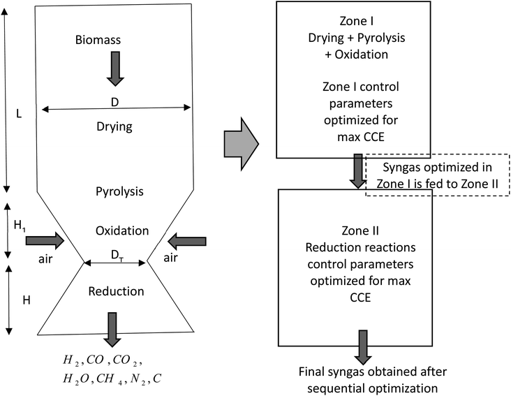
The schematic diagram of a downdraft gasifier for the present study is shown in Fig. 1. As observed in Fig. 1 the gasifier has a converging-diverging geometry which consists of four reaction stages namely drying, pyrolysis, oxidation, and reduction zone. Drying, pyrolysis and oxidation reactions are combined in zone I called pyro-oxidation zone. Drying process involves fractional evaporation of moisture content in biomass, while pyrolysis process involves breaking of biomass macro-molecules into volatile gases and char. The energy required to drive both drying and pyrolysis zone comes from oxidation zone which involves exothermic reactions of biomass with air. Thermodynamic equilibrium approach is implemented for modeling of pyro-oxidation zone (zone I). Since this section involves exothermic reaction which emits large amount of heat, the temperature in this section reaches maximum value compared to the rest of the gasifier geometry. Hence, thermodynamics equilibrium approach is justified for zone I. The gas composition and temperature at the end of zone I is then passed as input data to zone II i.e. diverging section of the gasifier called the reduction zone. This section consists of endothermic reduction reactions where actual gasification takes place. Zone II has been modeled using finite kinetic rate approach. The assumptions made during the development of the model are as follows:(i) The gaseous species in pyro-oxidation zone are in chemical equilibrium with each other.
(ii) The reduction zone is one-dimensional.
(iii) Specific heat of gas constituents is dependent on local temperature while specific heat of char is independent of temperature and considered constant.
(iv) The molecular weight of fixed carbon (ash neglected) in biomass is the same as that of elemental carbon.
(v) Since the reduction zone is enveloped by high temperature gases flowing upwards, the heat loss in zone II is considered negligible. Heat losses are only considered for oxidation zone where the temperatures are high.
In the following sub-sections, the detailed mathematical expressions for the modeling of zone I and zone II are discussed.
2.1 Modeling of pyro-oxidation zone
The chemical reaction for pyro-oxidation zone is given below. The reactants consist of biomass in CHO form, air as mixture of nitrogen and oxygen, and moisture content in biomass.| CHaObNc + m(O2 + 3.76N2) + wH2O → n1H2 + n2CO + n3CO2+ n4H2 + n5CH4 + n6N2 + n7C | (1) |
The chemical formula for biomass CHO form is calculated using the ultimate analysis data where coefficients a, b and c are calculated as follows:
 | (2) |
The coefficients for moisture content and of air supply are calculated as
 | (3) |

The right-hand side of eqn (1) represents the products of pyro-oxidation zone. There are a total of eight unknown variables consisting of molar concentrations of pyro-oxidation product gases and temperature of pyro-oxidation reactions. The equations required to calculate the unknowns are as follows:
(i) Three equations are derived from mass balance of carbon, hydrogen, and oxygen for the given reaction.
(ii) Further two equations are obtained by considering the equilibrium of gases in the water–gas shift reaction. Additionally, the methane formation in zone I is accounted for by considering the equilibrium of methanation reaction at the char surface. The equilibrium constants are calculated by estimating the net change in Gibb's function of the participating reactants and the products at the zonal temperature, as shown below:
For water–gas shift reaction CO + H2O ⇔ CO2 + H2
 | (4) |
For methanation reaction C + 2H2 ⇔ CH4
 | (5) |
(iii) Nitrogen remains inert and does not participate in any chemical reaction.
| n6 = 3.76 × m | (6) |
(iv) Datta et al.28 determined char composition based on assumption that the methane and carbon are assumed to form exclusively at the char surface. Hence, biomass char yield obtained from fixed carbon data in the proximate analysis is distributed in solid carbon and methane. Char is calculated as:
 | (7) |
The temperature of pyro-oxidation zone is determined by energy balance for all the constituents involved.
 | (8) |
2.2 Modeling of reduction zone
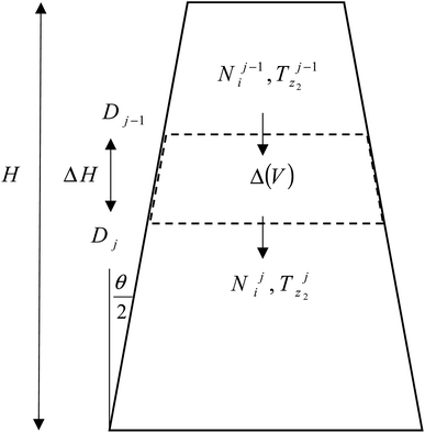
The product gases from zone I undergo reduction reactions in zone II to give final syngas output from the downdraft gasifier. The geometry of zone II is divergent in nature as shown in Fig. 2. The species concentration and temperature are determined by dividing zone II into finite control volumes. The mass and energy conservation principles are implemented across each control volume by accounting for the formation and consumption of gaseous species during the chemical reaction taking place in the reduction zone. The species concentration and zonal temperature across each control volume is assumed to be uniform. The gas composition and temperature at the exit of zone I goes as input to the reduction zone. The flow rate for each of the gaseous species i at the inlet of reduction zone is given as:
 | (9) |
The molar concentrations of gaseous species i at each control volume j is determined using the following relation:
| Nij = Nij−1 + RijΔVj | (10) |
 | (11) |
The term (Rij) in eqn (10) accounts for net formation/destruction of gaseous species across the control volume. To determine (Rij) it is important to study the chemical kinetics of the reduction reactions in zone II. The important chemical reactions taking place in zone II are shown in Table 1.
| Reaction | Chemical form |
|---|---|
| Boudouard reaction (R1) | C + CO2 ↔ 2CO |
| Water–gas reaction (R2) | C + H2O ↔ CO + H2 |
| Methane formation (R3) | C + 2H2 ↔ CH4 |
| Steam reforming (R4) | CH4 + H2O ↔ CO + 3H2 |
The rate of formation (Rij) of species in zone II is dependent on determining the Arrhenius kinetic rate equations for the reactions shown in Table 1. The reaction rates are determined based on the assumption that they are reversible, and it is dependent on pre-exponential factor (Ai), activation energy and zonal temperature. The kinetic parameters for forward reactions are taken from Giltrap et al.32 For the reverse reactions, the reaction rate is determined using the expressions for the forward reactions and equilibrium constants for the reactions. The expressions for kinetic rate constants for the reduction zone reactions are given in Table 2.
The reactions (R1 to R3) involve char reactions and hence, to account for the active reaction sites on the char surface, the rate of reactions is multiplied by the term CRF called char reactivity factor. Steam reformation reaction consists of shift reaction between the gaseous products in the reduction zone and hence, it is independent of char reactivity factor.33 The expressions for net rate of formation of species in zone II are given in Table 3.
| Species | Rj (mol m−3 s−1) |
|---|---|
| H2 | r2 − 2r3 + 3r4 |
| CO | 2r1 + r2 + r4 |
| CO2 | −r1 |
| H2O | −r2 − r4 |
| CH4 | r3 − r4 |
| N2 | 0 |
| C | −r1 − r2 − r3 |
The temperature at each control volume is determined by performing energy balance for each constituent gases entering and leaving the control volume along with the heat loss in the control volume. The energy balance equation for the reduction zone is given as:
 | (12) |
The hot gases coming from the gasifier exhaust move upwards and surround the reduction zone, and heat loss if any is negligible from this zone. Thus, the heat losses are neglected for the reduction zone in the present model.
3 Taguchi optimization and ANOVA
Taguchi method is an efficient approach for parametric analysis of a process and is particularly useful for the determination of optimum design parameters to improve the performance of a process. The main objective in this method is to achieve a robust system with respect to noise factors and obtain the corresponding optimum control parameters.34,35 The Taguchi method employs orthogonal arrays from design of experiments theory to analyze the effects of large number of variables using a small sample size experiment. It is well established that the inferences drawn from these small experiments are valid for the entire experiment in the region spanned across the levels of control parameters. Taguchi method has made major improvements in the applications of orthogonal arrays by utilizing simplified tabulated sets and linear graphs to fit specific processes.36 In this study, the gasification process is optimized sequentially for two zones, namely pyro-oxidation zone and reduction zone. For each zone, a set of five control parameters have been identified to maximize carbon conversion efficiency. The total number of experiments has been reduced from (35 = 243) to 27 and the given array is known as L27 array.37 The columns in an L27 array are mutually orthogonal i.e., for any given pair of columns all the combinations of the control parameters occur at equal number of times. A typical orthogonal array for five parameters at three levels is displayed in ESI.† The control parameters and their values at respective levels for the two-gasification zone under study are given in Tables 4 and 5.| Parameters | Symbol | Level | ||
|---|---|---|---|---|
| 1 | 2 | 3 | ||
| Equivalence ratio | ER | 0.32 | 0.37 | 0.42 |
| Moisture content (%) | MC | 10 | 15 | 20 |
| Air preheat temperature (K) | AT | 300 | 350 | 400 |
| Thermal conductivity of insulation (W m−1 K−1) | KTH | 1 | 8 | 15 |
| Thickness of insulation (mm) | THi | 1 | 10 | 20 |
| Parameters | Symbol | Level | ||
|---|---|---|---|---|
| 1 | 2 | 3 | ||
| Throat diameter (m) | Dth | 0.09 | 0.1 | 0.11 |
| Reduction zone length (m) | LR | 0.17 | 0.21 | 0.25 |
| Divergence angle (deg) | ANG | 30 | 45 | 60 |
| Char reactivity factor | CRF | 100 | 500 | 1000 |
| Reduction zone inlet temperature (K) | TRED | 1100 | 1200 | 1300 |
After constructing the orthogonal arrays, the next step is to conduct the experiments using the set combinations of control parameters and record the results. Once the experiments are conducted, the optimum control parameter settings are determined. In the present work, the results are obtained gas composition and temperature data is used to determine the response values of objective function. The results obtained are analyzed using the S/N ratios, which is a statistical parameter to evaluate the performance of a system/process. In simple terms, the S/N ratio indicates the ratio of mean (signal) and standard deviation (noise).38 The performance of a process will be evaluated based on three standard criteria for S/N ratios i.e., larger the better, smaller the better and nominal the better, expressions for which are given in ESI.†
The primary objective of the present research is to optimize the gasification process so that syngas with maximum energy with minimum concentration of pollutants, is obtained. Hence, we have chosen carbon conversion efficiency (CCE) as the objective function since it satisfies both the above mentioned criteria. Maximizing CCE ensures high concentration of combustible hydrocarbons in syngas with minimum concentration of char related impurities. The CCE for both the gasification zones is computed using the following expression:
 | (13) |
For Taguchi analysis, the optimum settings of control parameters need not necessarily be obtained from the orthogonal arrays. Hence, as a confirmation test, the objective function is evaluated again at the optimum settings obtained from the S/N ratio analysis.
Once the optimum combinations for the control parameters are determined, it is also important to evaluate the contribution of individual parameters. Analysis of variance (ANOVA) is a statistical tool used for analysis of Taguchi optimization results. ANOVA enables researchers to determine the most influential parameter by determining the percentage contributions of the control parameters. This is achieved by evaluating the mean response magnitude for all the parameters in the orthogonal array experiments. The detailed formulations to evaluate sum of squares, variance and percentage contribution in the ANOVA analysis are given in ESI.†
4 Results and discussion
4.1 Model validation
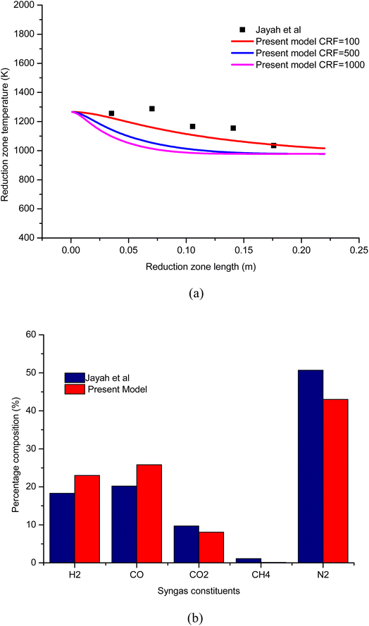
To establish the credibility and authenticity of the present model, the simulation results obtained from the model are compared with the experimental work carried out by Jayah et al.39 The input condition and gasifier dimensions for the validation problem are presented in Table 6. Validation results are examined for syngas composition and temperature with rubber wood as biomass feedstock. The validation results for temperature profile along the length of the gasifier is shown in Fig. 3(a). The results are examined for three different cases of CRF. The temperature profile for CRF = 100 is found to be in good agreement compared with the experimental results. As CRF increases the rate of endothermic reduction reactions increases which leads to faster decay in temperature profile and hence, the temperature profiles for CRF = 500 and 1000 are steeper. The temperature profiles for CRF = 500 and 1000 agree well with the kinetic studies published by Datta et al.28 and Diyoke et al.18 To further consolidate the accuracy of the model, the results for syngas composition are also verified. The percentage composition for syngas constituents at 16% moisture content and A/F ratio 2.2 is compared with Jayah et al.39 as shown in Fig. 3(b). It can be observed that the predicted syngas composition is in reasonable agreement with the experimental results. The error noticed in the calculation of syngas composition and temperature can be attributed to the model assumptions like ideal gas, char formulation approximated for pure carbon, isobaric process, and steady state conditions in the gasifier etc.| Biomass | Rubber wood |
|---|---|
| Ultimate analysis data | Carbon = 50.6%, hydrogen = 6.5, oxygen = 42.2%, nitrogen = 1.1% |
| Geometric properties | D = 920 mm, DT = 100 mm, L = 1150 mm, H1 = 750 mm, H = 250 mm, Div. angle = 61° |
4.2 Taguchi optimization of pyro-oxidation zone
The pyro-oxidation zone consists of complex chemical processes i.e. drying, pyrolysis, oxidation reactions. Each of these phases are controlled by many thermo-physical properties. This zone is zero-dimensional since it is modeled using thermodynamic equilibrium approach. Hence, the gas composition and temperature in this zone is independent of gasifier geometry. The syngas composition in zone I is only dependent on the properties of biomass, nature of oxidant and heat losses in the zone. The final objective is to obtain syngas with maximum energy density with minimum contamination and impurities and thus the overall performance of the gasifier by maximizing carbon conversion efficiency can also be improved. For this purpose, five control parameters are identified at three levels as shown in Table 4. For zone I, two properties i.e., equivalence ratio (ER) and air preheat temperature are related to oxidant. Moisture content is a property of biomass and two properties of insulating material i.e., thermal conductivity and thickness of insulation are selected for optimization of pyro-oxidation zone. The orthogonal array for different configurations of these parameters along with the respective carbon conversion efficiency and S/N ratios are shown in Table 7.| ER | Moisture (%) | Preheat temp. (K) | Thermal conductivity (W m−1 K−1) | Thickness of insulation (mm) | CCE (%) | SNRA1 |
|---|---|---|---|---|---|---|
| 0.32 | 10 | 300 | 1 | 1 | 76.0727 | 39.49 |
| 0.32 | 10 | 300 | 1 | 10 | 75.4217 | 39.46 |
| 0.32 | 10 | 300 | 1 | 20 | 75.2481 | 39.45 |
| 0.32 | 15 | 350 | 8 | 1 | 77.2232 | 39.57 |
| 0.32 | 15 | 350 | 8 | 10 | 76.9434 | 39.56 |
| 0.32 | 15 | 350 | 8 | 20 | 76.7526 | 39.55 |
| 0.32 | 20 | 400 | 15 | 1 | 78.2073 | 39.65 |
| 0.32 | 20 | 400 | 15 | 10 | 78.0284 | 39.64 |
| 0.32 | 20 | 400 | 15 | 20 | 77.8813 | 39.63 |
| 0.37 | 10 | 350 | 15 | 1 | 70.6818 | 38.86 |
| 0.37 | 10 | 350 | 15 | 10 | 70.5915 | 38.85 |
| 0.37 | 10 | 350 | 15 | 20 | 70.517 | 38.85 |
| 0.37 | 15 | 400 | 1 | 1 | 71.2495 | 38.91 |
| 0.37 | 15 | 400 | 1 | 10 | 70.8612 | 38.88 |
| 0.37 | 15 | 400 | 1 | 20 | 70.7535 | 38.87 |
| 0.37 | 20 | 300 | 8 | 1 | 73.3345 | 39.08 |
| 0.37 | 20 | 300 | 8 | 10 | 73.1134 | 39.06 |
| 0.37 | 20 | 300 | 8 | 20 | 72.9613 | 39.05 |
| 0.42 | 10 | 400 | 8 | 1 | 66.3642 | 38.29 |
| 0.42 | 10 | 400 | 8 | 10 | 66.2687 | 38.28 |
| 0.42 | 10 | 400 | 8 | 20 | 66.2023 | 38.27 |
| 0.42 | 15 | 300 | 15 | 1 | 67.6887 | 38.41 |
| 0.42 | 15 | 300 | 15 | 10 | 67.609 | 38.4 |
| 0.42 | 15 | 300 | 15 | 20 | 67.543 | 38.4 |
| 0.42 | 20 | 350 | 1 | 1 | 68.2238 | 38.46 |
| 0.42 | 20 | 350 | 1 | 10 | 67.8798 | 38.43 |
| 0.42 | 20 | 350 | 1 | 20 | 67.7829 | 38.42 |
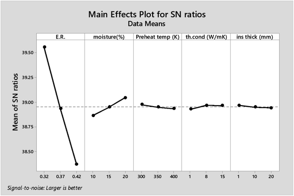
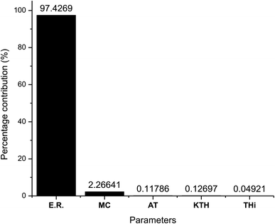
As observed from Table 7 the carbon conversion efficiency for the 27 trial runs varies between 66.2% and 78.2%. The optimum setting for the control parameters from the S/N ratio diagram is ER(1)MC(3)AT(1)Kth(2)Thi(1). When the confirmation trial run is conducted at these settings, the CCE obtained is 81.05%, which is an improvement on the highest CCE attained from the Taguchi results. The S/N values for each control parameter for zone I are presented in Table 8 and the plot of S/N ratio vs. levels is given in Fig. 4. It is evident from Fig. 4 that the equivalence ratio is the most significant parameter and moisture content in biomass becomes the second influential parameter. Air preheat temperature and insulation parameters have negligible effects. The effect of optimum setting of control parameters on CCE in zone I is explained as follows: equivalence ratio signifies the amount of air supply to the gasifier. Level I for equivalence ratio signifies lower amount of air supply. With an increase in air supply there is an increase in concentration of H2O, CO2 and N2 gas while concentration of H2, CO, CH4 gases decrease. For the ER range of 0.32–0.42 in the present analysis, there in a net decrease in the concentration of carbon based syngas constituents compared to other gases. Hence Taguchi analysis suggests level 1 for ER as the optimum level. Increase in moisture content has two fundamental effects, (i) temperature in zone I will decrease because some amount of heat of reaction is spent in overcoming the latent heat of vaporization of steam and (ii) excess moisture will inject extra oxygen molecules which oxidizes CO into CO2. Hence, with an increase in moisture content, there will be a slight drop in CO gas concentration resulting in an increase in CO2 gas concentration. Since CO2 gas is heavier than CO gas, there is slight increase in CCE at higher levels of moisture content. Air preheating temperature, thermal conductivity and insulation thickness have common effect i.e., they minimize heat losses to ambient and maintain high temperature in zone I. As the chemical reactions in pyro-oxidation zone are exothermic reactions, naturally the temperature of the zone remains extremely high since exothermic reactions emit large amounts of heat. Hence, at such and corresponding change in gas composition due to controlling heat loss is very negligible compared to the change in composition caused by exothermicity of reaction. Thus, it is noticed that the influence of air preheat temperature and insulation properties is very minimal compared to the properties of chemical oxidants. These results are further validated by ANOVA (Table 9) where ER is the most influencing parameter with 97.7% influence followed by moisture content which has 2.2% influence while the other three parameters have negligible influence on CCE in zone I. The percentage contribution of all the control parameters for zone I is displayed in Fig. 5.
| Level | ER | Moisture (%) | Preheat temp. (K) | Thermal conductivity (W m−1 K−1) | Thickness of insulation (mm) |
|---|---|---|---|---|---|
| 1 | 39.56 | 38.87 | 38.98 | 38.93 | 38.97 |
| 2 | 38.94 | 38.95 | 38.95 | 38.97 | 38.95 |
| 3 | 38.37 | 39.05 | 38.94 | 38.97 | 38.94 |
| Delta | 1.18 | 0.18 | 0.04 | 0.04 | 0.03 |
| Rank | 1 | 2 | 3 | 4 | 5 |
| Parameters | DF | Seq SS | Adj SS | Adj MS | F | P | Percentage contribution |
|---|---|---|---|---|---|---|---|
| ER | 2 | 6.31528 | 6.31528 | 3.15764 | 61![[thin space (1/6-em)]](https://www.rsc.org/images/entities/char_2009.gif) 977.09 977.09 |
0 | 97.4269 |
| Moisture (%) | 2 | 0.14691 | 0.14691 | 0.07346 | 1441.76 | 0 | 2.266406 |
| Preheat temp. (K) | 2 | 0.00764 | 0.00764 | 0.00382 | 74.93 | 0 | 0.117864 |
| Thermal conductivity (W m−1 K−1) | 2 | 0.00823 | 0.00823 | 0.00412 | 80.81 | 0 | 0.126966 |
| Thickness of insulation (mm) | 2 | 0.00319 | 0.00319 | 0.00159 | 31.3 | 0 | 0.049213 |
| Residual error | 16 | 0.00082 | 0.00082 | 0.00005 | 0.01265 | ||
| Total | 26 | 6.48207 | 100 |
4.3 Taguchi optimization of reduction zone
The optimized syngas composition and temperature from zone I is now taken as input for the reduction zone (zone II). A separate optimization strategy is implemented for the reduction zone as the final gasification takes place in this zone. The syngas composition in zone II is governed by the diverging geometry and chemical kinetics of reduction reactions. For optimization of CCE in zone II, five control parameters are identified. Three parameters representing the geometry in zone II are throat diameter at inlet, length of reduction zone, divergence angle, while the other two parameters are namely char reactivity factor and reduction zone temperature and these parameters control the net rate of reactions in the reduction zone. The Taguchi optimization results for 27 trial runs in the reduction zone are given in Table 10.| Dth (m) | Length (m) | Div. ang (deg) | CRF | Tred (K) | CCE (%) | S/N Ratio |
|---|---|---|---|---|---|---|
| 0.09 | 0.17 | 30 | 100 | 1100 | 84.25 | 38.51 |
| 0.09 | 0.17 | 30 | 100 | 1200 | 88.47 | 38.94 |
| 0.09 | 0.17 | 30 | 100 | 1300 | 92.98 | 39.37 |
| 0.09 | 0.21 | 60 | 500 | 1100 | 87.37 | 38.83 |
| 0.09 | 0.21 | 60 | 500 | 1200 | 91.97 | 39.27 |
| 0.09 | 0.21 | 60 | 500 | 1300 | 96.40 | 39.68 |
| 0.09 | 0.25 | 90 | 1000 | 1100 | 87.80 | 38.87 |
| 0.09 | 0.25 | 90 | 1000 | 1200 | 92.10 | 39.29 |
| 0.09 | 0.25 | 90 | 1000 | 1300 | 96.17 | 39.66 |
| 0.095 | 0.17 | 60 | 1000 | 1100 | 87.66 | 38.86 |
| 0.095 | 0.17 | 60 | 1000 | 1200 | 92.08 | 39.28 |
| 0.095 | 0.17 | 60 | 1000 | 1300 | 96.28 | 39.67 |
| 0.095 | 0.21 | 90 | 100 | 1100 | 85.03 | 38.59 |
| 0.095 | 0.21 | 90 | 100 | 1200 | 89.45 | 39.03 |
| 0.095 | 0.21 | 90 | 100 | 1300 | 94.02 | 39.46 |
| 0.095 | 0.25 | 30 | 500 | 1100 | 87.52 | 38.84 |
| 0.095 | 0.25 | 30 | 500 | 1200 | 92.05 | 39.28 |
| 0.095 | 0.25 | 30 | 500 | 1300 | 96.37 | 39.68 |
| 0.1 | 0.17 | 90 | 500 | 1100 | 87.37 | 38.83 |
| 0.1 | 0.17 | 90 | 500 | 1200 | 91.97 | 39.27 |
| 0.1 | 0.17 | 90 | 500 | 1300 | 96.40 | 39.68 |
| 0.1 | 0.21 | 30 | 1000 | 1100 | 87.81 | 38.87 |
| 0.1 | 0.21 | 30 | 1000 | 1200 | 92.11 | 39.29 |
| 0.1 | 0.21 | 30 | 1000 | 1300 | 96.16 | 39.66 |
| 0.1 | 0.25 | 60 | 100 | 1100 | 85.67 | 38.66 |
| 0.1 | 0.25 | 60 | 100 | 1200 | 90.21 | 39.11 |
| 0.1 | 0.25 | 60 | 100 | 1300 | 94.80 | 39.54 |
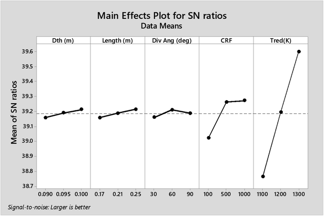
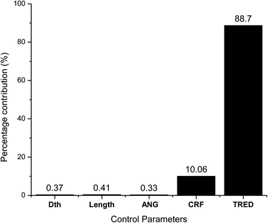
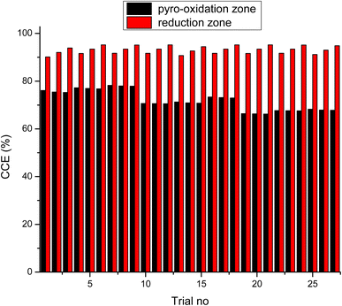
As observed from the table, the carbon conversion efficiency varies from 84.25% to 96.4% for 27 trial runs conducted for the reduction zone. The S/N values for each control parameter for zone II are presented in Table 11 and the plot of S/N ratio vs. levels is depicted in Fig. 6. From the S/N ratio diagram, the optimum settings of control parameters is observed to be Dth(3)LR(3)ANG(2)CRF(3)TRED(3). When the confirmation trial at the optimized configuration is conducted the carbon conversion efficiency is obtained as 96.04%. From Fig. 6 it is also observed that the most affecting parameter for CCE in zone II is the temperature in zone II. Now as seen from eqn (12), the final species concentration is dependent on the rate of reaction for each control volume in zone II. Char consumption in reduction zone happens to take place in three chemical reactions i.e., Boudouard reaction, water–gas reaction and methanation reaction. All the three reactions are endothermic reactions, which means large amounts of energy must be absorbed by the reactions to be driven forward, leading to the formation of the final gaseous constituents, CO, CO2 and CH4. The net rate of reactions for the formation of these compounds also increases with increase in temperature, hence, the high temperature in zone II is necessary to obtain high carbon conversion efficiency. After the zonal temperature, the char reactivity factor is the second most influential parameter for optimizing carbon conversion efficiency. Now, the three levels of CRF considered in the study are 100![[thin space (1/6-em)]](https://www.rsc.org/images/entities/char_2009.gif) 500 and 1000. Char reactivity factor is an indicator of active sites on char surface in a downdraft gasifier. Higher the char reactivity factor, the faster is the char decay and the steeper will be the temperature profile in the reduction zone. As discussed above, having an overall high temperature in the reduction zone is beneficial. Hence, for CRF = 1000, the CCE obtained is 96.04% which is slightly less than the CCE of 96.4% for CRF = 500. These results are again validated by ANOVA results (Table 12) which indicate that temperature and CRF are the most influential parameters. The other three parameters, namely throat diameter in reductions zone, length of reduction zone and divergence angle have comparatively negligible influence on the optimization of gasifier length. All the three parameters represent the dimensions of the reduction zone. Increase in these parameters results in the increase in the size of control volume in the reduction zone. With increased control volume, the rate of reduction zone reactions increases and since these are predominantly endothermic reactions, the temperature profiles will be steeper for increased reaction rates. Hence, even though increased control volume helps for faster char conversion, the counter effects of reduction in temperature in zone II leads to slight reduction in the overall output carbon conversion efficiency. Thus the control parameter settings Dth(1)LR(2)ANG(2)CRF(2)TRED(3) at 6th trial run give slightly better CCE value than the one obtained from S/N ratio analysis. The ANOVA results validate the results obtained by the Taguchi analysis indicating TRED as the most influential parameter with (88%) followed by char reactivity factor (10%). The percentage contribution of all the control parameters for zone II is displayed in Fig. 7. The comparison of CCE for all the 27 trial runs in zone I and zone II are displayed in Fig. 8. The optimal settings for control parameters and the corresponding CCE are summarized in Table 13.
500 and 1000. Char reactivity factor is an indicator of active sites on char surface in a downdraft gasifier. Higher the char reactivity factor, the faster is the char decay and the steeper will be the temperature profile in the reduction zone. As discussed above, having an overall high temperature in the reduction zone is beneficial. Hence, for CRF = 1000, the CCE obtained is 96.04% which is slightly less than the CCE of 96.4% for CRF = 500. These results are again validated by ANOVA results (Table 12) which indicate that temperature and CRF are the most influential parameters. The other three parameters, namely throat diameter in reductions zone, length of reduction zone and divergence angle have comparatively negligible influence on the optimization of gasifier length. All the three parameters represent the dimensions of the reduction zone. Increase in these parameters results in the increase in the size of control volume in the reduction zone. With increased control volume, the rate of reduction zone reactions increases and since these are predominantly endothermic reactions, the temperature profiles will be steeper for increased reaction rates. Hence, even though increased control volume helps for faster char conversion, the counter effects of reduction in temperature in zone II leads to slight reduction in the overall output carbon conversion efficiency. Thus the control parameter settings Dth(1)LR(2)ANG(2)CRF(2)TRED(3) at 6th trial run give slightly better CCE value than the one obtained from S/N ratio analysis. The ANOVA results validate the results obtained by the Taguchi analysis indicating TRED as the most influential parameter with (88%) followed by char reactivity factor (10%). The percentage contribution of all the control parameters for zone II is displayed in Fig. 7. The comparison of CCE for all the 27 trial runs in zone I and zone II are displayed in Fig. 8. The optimal settings for control parameters and the corresponding CCE are summarized in Table 13.
| Level | Dth (m) | Length (m) | Div. ang | CRF | Tred (K) |
|---|---|---|---|---|---|
| 1 | 39.16 | 39.16 | 39.16 | 39.02 | 38.76 |
| 2 | 39.19 | 39.19 | 39.21 | 39.26 | 39.19 |
| 3 | 39.21 | 39.21 | 39.19 | 39.27 | 39.6 |
| Delta | 0.05 | 0.06 | 0.05 | 0.25 | 0.84 |
| Rank | 4 | 3 | 5 | 2 | 1 |
| Source | DF | Seq SS | Adj SS | Adj MS | F | P | Percentage contribution (%) |
|---|---|---|---|---|---|---|---|
| Dth | 2 | 0.01314 | 0.01314 | 0.00657 | 21.29 | 0 | 0.37 |
| Length | 2 | 0.01444 | 0.01444 | 0.00722 | 23.39 | 0 | 0.41 |
| Div. ang | 2 | 0.01165 | 0.01165 | 0.00582 | 18.87 | 0 | 0.33 |
| CRF | 2 | 0.35929 | 0.35929 | 0.17965 | 582.11 | 0 | 10.06 |
| Tred | 2 | 3.16756 | 3.16756 | 1.58378 | 5131.94 | 0 | 88.70 |
| Residual error | 16 | 0.00494 | 0.00494 | 0.00031 | 0.138 | ||
| Total | 26 | 3.57102 | 100 |
| Zone | Orthogonal array | Taguchi method | ||
|---|---|---|---|---|
| Optimal settings | CCE (%) | Optimal settings | CCE (%) | |
| Pyro-oxidation | ER(1)MC(3)AT(3)Kth(3)Thi(1) | 78.2 | ER(1)MC(3)AT(1)Kth(3)Thi(1) | 81.04 |
| Reduction | Dth(1)LR(2)ANG(2)CRF(2)TRED(3) | 96.4 | Dth(3)LR(3)ANG(2)CRF(3)TRED(3) | 96.04 |
4.4 Performance analysis of gasifier at optimized parameters
Once the optimal settings for control parameters are obtained, the gasifier's performance is evaluated at these optimal settings. Fig. 9(a) and (b) depict the temperature and gas composition profile when the downdraft gasifier is configured at the optimal settings after sequential Taguchi optimization. The concentration of H2 and CO gas increases while the concentration of CO2, H2O and CH4 decreases along the length of the gasifier. Nitrogen gas remains inert but there is a slight drop in its percentage concentration since the total gas concentration increases. From Fig. 9 it is evident that the process reaches equilibrium after 0.125 m. This is because at the inlet of zone II, the temperature is maximum and the kinetic reaction rates which drive the reduction reactions are also highest at this point. The endothermic reactions consume substantial amounts of combustion energy due to which the temperature drops sharply from 0 to 0.125 m. Since the char and gaseous reactants get consumed very fast in the initial stage, the concentration of char and gaseous products is now reduced drastically. The char surface is now covered with CO and H2 which makes the surface reactions inactive. Hence, the gas composition and temperature in the reduction zone reach equilibrium after length 0.125 m.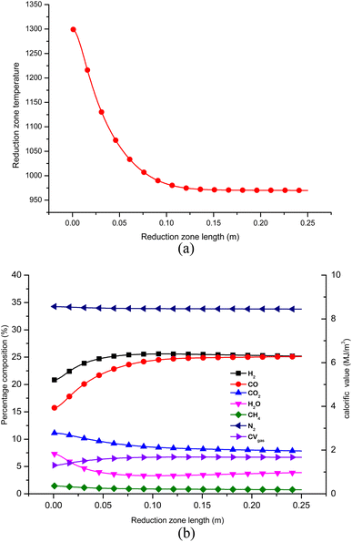 | ||
| Fig. 9 (a) Temperature profile in reduction zone for optimized configuration of gasifier. (b) Gas composition in zone II at optimized configurations. | ||
The gas composition, temperature and calorific value are also compared against the average experimental yield for a downdraft gasifier presented in the review study by Villetta et al.40 in Fig. 10. It is evident from Fig. 10 that the yield of H2 and CO gas for the optimized model is better when compared with the average experimental yield. The improvement in the output of H2 and CO gas is found to be 48.11% and 19.47% respectively. The yield of CO2 gas is also significantly less which agrees with one of the objectives of the optimization analysis. The percentage drop in CO2 gas against the average experimental yield is 39.7%. The improvement in gasifier performance for optimized configuration can be explained by studying the influence of most affecting parameters. With the optimum settings of control parameters, the equivalence ratio is set at level 1 (0.32) and level 3 is obtained for reduction zone temperature (1300) and CRF (1000). The advantage of cutting air supply is that the yield of H2 and CO in pyro-oxidation zone is higher since their oxidation into H2O and CO2 is prevented by avoiding excess air supply. Higher yield at pyro-oxidation zone is carried forward to the reduction zone, where there is natural increase in the yield of H2 and CO due to reduction zone reactions and shift reactions. Higher values of reduction zone temperature and CRF ensures that the rate of endothermic reactions is sufficiently high to give high yield of H2 and CO gas. With rise in concentration of CO gas for optimized settings there is natural decline in concentration of CO2 gas. CH4 formation takes place at lower temperatures since its formation is dependent upon the shift reactions. But overall the effect of optimum configurations leads to increase in temperature in zone II. Hence, the CH4 yield for optimized settings is below the average yield. Nitrogen remains inert and does not take part in any chemical reaction and its absolute concentration remains the same but percentage composition drops owing to rise in the concentration of other gaseous species. As a result of the increase in the overall concentration of the combustibles gases the calorific value of syngas for the optimized model is 17.79% higher compared to the average experimental value.
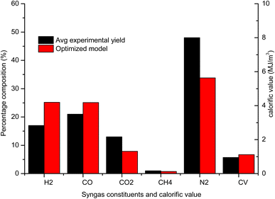 | ||
| Fig. 10 Comparison final gas output and calorific value of optimized gasifier model with average experimental yield. | ||
5 Conclusions
A robust mathematical model was developed for sequential optimization of pyro-oxidation and reduction zone reactions in a downdraft gasifier using thermodynamic equilibrium model and kinetic reactions. To obtain energy intense syngas with minimum concentration of contaminants, maximization of carbon conversion efficiency was selected as the objective function. The Taguchi method was implemented for sequential process optimization by treating the whole gasification process taking place in two zones, pyro-oxidation, and reduction zones. Analysis of variance (ANOVA) is employed to determine the most influential parameters. Once the optimal settings of control parameters were determined, the gasifier performance was compared with available experimental results for rubber wood. Following are the important conclusions from the research work:(i) The optimized value of CCE for zone I is 81.04%. Since equivalence ratio (ER) governs the combustion reactions and temperature in zone I, it is the most influential parameter with 97% contribution. Moisture content in biomass has 2% contribution on CCE in zone I.
(ii) The chemical kinetics for reduction reactions is strongly controlled by inlet temperature and char reactivity factor, which are the most influencing parameters with 88% and 10% contribution, respectively. The final CCE obtained is 96.04% which limits the concentration of char contaminants to less than 4%, fulfilling the objectives of the present research.
(iii) Variation in geometric parameters and heat loss parameters only affect the slope of temperature curve and have minimal influence on the final temperature due to which its influence on CCE is less than 2%.
(iv) The gasifier, when configured for optimal settings showed improvement in yield of H2 and CO gas by 48.11% and 19.47% respectively with improvement in calorific value being 17.79% when compared with average experimental yield. The optimized model also gives significantly lesser yield for CO2 gas with a reduction of 39.7% when compared to average experimental values.
Abbreviations
| A/F | Air to fuel ratio |
| CGE | Cold gas efficiency |
| HHV | Higher heating value |
Nomenclature
| a | Fraction of hydrogen in biomass |
| b | Fraction of oxygen in biomass |
| c | Fraction of nitrogen in biomass |
| ni | Number of moles of gas constituents |
| Ai | Frequency factor of ith reaction (1/s) |
| Cp | Specific heat (J mol−1 K−1) |
| CRF | Char reactivity factor |
| Ei | Activation energy (J mol−1) |
| g0i | Gibbs function |
| h0f | Heat of formation (J mol−1) |
| Keq | Equilibrium constant |
| ni | Number of moles of gas constituents in zone 1 (moles) |
| Ni | Gas flow rate in zone II (mol s−1) |
| m | Air supply coefficient |
| ri | Rate of ith reaction (mol m−3 s−1) |
| Rx | Net rate of reaction of gaseous species (mol m−3 s−1) |
| w | Weight fraction of moisture content in biomass |
| y | Mole fraction of gaseous species |
Data availability
Data will be made available upon request to the corresponding author.Author contributions
Rupesh Palange: modelling and simulation, analysis of results, writing – original draft preparation. Murugesan Krishnan: analysis of results, writing – reviewing and editing.Conflicts of interest
The authors have no relevant financial or non-financial interests to disclose.Acknowledgements
This research did not receive any specific grant from funding agencies in the public, commercial, or not-for-profit sectors.References
- P. Sharma, B. Gupta, M. Pandey, K. Singh Bisen and P. Baredar, Mater. Today Proc., 2020, 46, 5333–5341 CrossRef.
- H. Haberl, D. Sprinz, M. Bonazountas, P. Cocco, Y. Desaubies, M. Henze, O. Hertel, R. K. Johnson, U. Kastrup, P. Laconte, E. Lange, P. Novak, J. Paavola, A. Reenberg, S. van den Hove, T. Vermeire, P. Wadhams and T. Searchinger, Energy Policy, 2012, 45, 18–23 CrossRef PubMed.
- T. K. Patra and P. N. Sheth, Renewable Sustainable Energy Rev., 2015, 50, 583–593 CrossRef CAS.
- A. D. Korberg, B. V. Mathiesen, L. R. Clausen and I. R. Skov, Smart Energy, 2021, 1, 100006 CrossRef.
- V. S. Sikarwar, M. Zhao, P. Clough, J. Yao, X. Zhong, M. Z. Memon, N. Shah, E. J. Anthony and P. S. Fennell, Energy Environ. Sci., 2016, 9, 2939–2977 RSC.
- S. Jarungthammachote and A. Dutta, Energy, 2007, 32, 1660–1669 CrossRef CAS.
- S. Jarungthammachote and A. Dutta, Energy Convers. Manage., 2008, 49, 1345–1356 CrossRef CAS.
- Z. A. Zainal, R. Ali, C. H. Lean and K. N. Seetharamu, Energy Convers. Manage., 2001, 42, 1499–1515 CrossRef CAS.
- A. Melgar, J. F. Pérez, H. Laget and A. Horillo, Energy Convers. Manage., 2007, 48, 59–67 CrossRef CAS.
- S. Khanmohammadi, K. Atashkari and R. Kouhikamali, Int. J. Chem. Eng., 2016, 2016, 2639241 Search PubMed.
- S. Syed, I. Janajreh and C. Ghenai, Int. J. Therm. Environ. Eng., 2011, 4, 47–54 CrossRef.
- S. Shabbar and I. Janajreh, Energy Convers. Manage., 2013, 65, 755–763 CrossRef CAS.
- Y. Wang and C. M. Kinoshita, Sol. Energy, 1993, 51, 19–25 CrossRef CAS.
- D. L. Giltrap, R. Mckibbin and G. R. G. Barnes, Sol. Energy, 2003, 74, 85–91 CrossRef CAS.
- B. V. Babu and A. S. Chaurasia, Energy Convers. Manage., 2003, 44, 2251–2275 CrossRef CAS.
- J. K. Ratnadhariya and S. A. Channiwala, Renewable Energy, 2009, 34, 1050–1058 CrossRef CAS.
- N. Gao and A. Li, Energy Convers. Manage., 2008, 49, 3483–3490 CrossRef CAS.
- C. Diyoke, N. Gao, M. Aneke, M. Wang and C. Wu, Appl. Therm. Eng., 2018, 142, 444–456 CrossRef CAS.
- T. H. Jayah, L. Aye, R. J. Fuller and D. F. Stewart, Biomass Bioenergy, 2003, 25, 459–469 CrossRef CAS.
- A. A. Ahmad, N. A. Zawawi, F. H. Kasim, A. Inayat and A. Khasri, Renewable Sustainable Energy Rev., 2016, 53, 1333–1347 CrossRef CAS.
- S. Nanda, J. Isen, A. K. Dalai and J. A. Kozinski, Energy Convers. Manage., 2016, 110, 296–306 CrossRef CAS.
- Y. Graz, S. Bostyn, T. Richard, P. E. Bocanegra, E. De Bilbao, J. Poirier and I. Gokalp, J. Supercrit. Fluids, 2016, 107, 182–188 CrossRef CAS.
- D. Hendry, C. Venkitasamy, N. Wilkinson and W. Jacoby, Bioresour. Technol., 2011, 102, 3480–3487 CrossRef CAS PubMed.
- Y. Lu, L. Guo, X. Zhang and C. Ji, Int. J. Hydrogen Energy, 2012, 37, 3177–3185 CrossRef.
- J. A. Okolie, S. Nanda, A. K. Dalai and J. A. Kozinski, Energy Convers. Manage., 2020, 208, 112545 CrossRef CAS.
- R. Hasanzadeh, M. Mojaver, T. Azdast and C. B. Park, Chem. Eng. J., 2022, 430, 132958 CrossRef CAS.
- J. A. Okolie, E. I. Epelle, S. Nanda, D. Castello, A. K. Dalai and J. A. Kozinski, J. Supercrit. Fluids, 2021, 173, 105199 CrossRef CAS.
- P. C. Roy, A. Datta and N. Chakraborty, Int. J. Energy Res., 2009, 33, 833–851 CrossRef CAS.
- M. Chase, J. Phys. Chem. Ref. Data, 1998, Monograph 9, 1952 Search PubMed.
- R. Perry, D. Green and J. Maloney, Perry's Chemical Engineers' Handbook, 1997 Search PubMed.
- M. W. Thring, The Science of Flames and Furnaces, Chapman & Hall, London, 2nd edn, 1962 Search PubMed.
- D. L. Giltrap, PhD thesis, Massey University, 2002 Search PubMed.
- R. Budhathoki, Masters' thesis, University of Jyvaskyla, 2013, vol. 1–96 Search PubMed.
- J. F. C. Khaw, B. S. Lim, L. E. N. Lim, Z. P. Chang, Y. W. Li, N. Fatima, R. Jeyapaul, P. Shahabudeen and K. Krishnaiah, Neurocomputing, 1995, 7, 1331–1337 CrossRef.
- J. F. C. Khaw, B. S. Lim and L. E. N. Lim, Neurocomputing, 1995, 7, 225–245 CrossRef.
- R. Jeyapaul, P. Shahabudeen and K. Krishnaiah, Int. J. Adv. Manuf. Technol., 2005, 26, 1331–1337 CrossRef.
- M. S. Phadke, Quality Engineering Using Robust Design, Prentice Hall PTR, Upper Saddle River, NJ, USA, 1st edn, 1995 Search PubMed.
- C. G. Mota-Gutiérrez, E. O. Reséndiz-Flores and Y. I. Reyes-Carlos, Int. J. Qual. Reliab. Manage., 2018, 35, 596–613 CrossRef.
- T. H. Jayah, L. Aye, R. J. Fuller and D. F. Stewart, Biomass Bioenergy, 2003, 25, 459–469 CrossRef CAS.
- M. La Villetta, M. Costa and N. Massarotti, Renewable Sustainable Energy Rev., 2017, 74, 71–88 CrossRef CAS.
Footnote |
| † Electronic supplementary information (ESI) available. See DOI: https://doi.org/10.1039/d3ra00667k |
| This journal is © The Royal Society of Chemistry 2023 |

