
 Open Access Article
 This Open Access Article is licensed under a Creative Commons Attribution-Non Commercial 3.0 Unported Licence
Mechanistic study of Al2O3 coating effects on lithium deposition and dissolution reaction
Tomohiro Kakimia,
Shuntaro Miyakawab,
Sou Taminato *a,
Takaya Saitob,
Daisuke Moria and
Nobuyuki Imanishia
*a,
Takaya Saitob,
Daisuke Moria and
Nobuyuki Imanishia
aDepartment of Chemistry for Materials, Graduate School of Engineering, Mie University, Tsu, Mie 514-8507, Japan. E-mail: taminato@chem.mie-u.ac.jp; Fax: +81-59-231-9478; Tel: +81-59-231-9968
bAdvanced Battery Research Office, Research Institute of Advanced Technology, SoftBank Corporation, Kaigan, Minato-Ku, Tokyo 105-7529, Japan
First published on 20th March 2023
Abstract
Lithium metal anodes show great promise for use in next-generation secondary batteries, but they suffer from lithium dendrite growth, as well as other issues, which cause safety problems and result in a loss of capacity with time. The use of artificial inorganic solid electrolyte interphase (SEI) layers, such as those comprising Al2O3, is a promising way to mitigate these disadvantages, but the mechanism behind these observed improvements remains poorly understood. Therefore, in this study, using pulsed laser deposition (PLD), the surface of a Cu electrode was coated with a physicochemically stable and mechanically strong Al2O3 thin film, and the effects of the film coating on the lithium deposition and dissolution behaviour were investigated. When the morphology of the deposits was evaluated by scanning electron microscopy, small lithium nuclei (approximately 0.2 μm in diameter) were observed to be deposited uniformly over the entire surface of the uncoated Cu electrode in the initial electrodeposition, and these grew into needle-like crystals from the nuclei. After 60 min of electrodeposition, the needle-like precipitates had aggregated and grown into three-dimensional structures with dendritic form. In contrast, on the surface of the Cu electrode modified with Al2O3 by PLD for 1 h, lithium clusters of about 50 μm in diameter were found to be aggregated and precipitated in the initial stages of electrodeposition. Notably, this is the first report of lithium deposition on Al2O3 thin films. With further cycling, the precipitates grew into two-dimensional flat plates. Analysis of the SEI film formed during the first deposition reaction revealed that the Al2O3 coating reduced the thickness of the SEI compared to that of the uncoated electrode. Therefore, the Al2O3 coating suppressed the decomposition of the electrolyte with the Cu electrode. The use of Al2O3 coatings results in (i) the growth of two-dimensional lithium clusters with an island shape on the Al2O3 thin film, and these could ensure a uniform electron conduction path to the electrode; in addition, (ii) the inhibited electrolyte decomposition caused by the low-surface-area lithium clusters and the low electronic conductivity of the Al2O3 thin film. These improve the coulombic efficiency and cycling behaviour.
Introduction
Metallic lithium is attracting attention as an ideal negative electrode for next-generation high-energy-density secondary batteries.1 Metallic lithium has a very high theoretical capacity of 3860 mA h g−1 by weight and 2062 mA h cm−3 by volume, which is about 10-times the capacity per weight of graphite (the negative electrode used in existing lithium secondary batteries), and its electrode potential is −3.045 V, which is less than that of the standard hydrogen electrode. Therefore, metallic lithium is a highly promising negative electrode material for next-generation high-energy-density secondary batteries such as Li–S batteries and Li–air batteries.2–6Despite their promise, lithium metal batteries have several problems related to safety and cycling stability. These problems arise because the lithium metal negative electrode has a very high chemical and electrochemical reactivity and, thus, spontaneously reacts with organic electrolytes and undergoes side reactions, such as solid electrolyte interphase (SEI) formation on the surface and Li dendrite formation;7 further, the interfacial stability decreases because of the volume expansion associated with the deposition/dissolution reactions.8 The SEI, which is produced as a side reaction, forms a mosaic-like multi-layered structure comprising a mixture of organic and inorganic compounds.9,10 In such a heterogeneous chemical structure, each component has different ionic and electronic conductivities, which results in heterogeneous reactivity on the lithium electrode surface and is one of the causes of dendrite growth.11 In particular, the coulombic efficiency is reduced as a result of dendrite growth because it causes the formation of electrochemically inactive “dead lithium”, and the continuous consumption of the electrolyte on cycling. Furthermore, if the dendrites penetrate the separator and come into contact with the positive electrode, internal short-circuits occur, which can result in fire or explosion.12,13
Consequently, there has been extensive research into methods to suppress dendrite formation effectively and, thus, improve the safety and cyclic stability of lithium metal batteries. Examples of these methods include (i) the introduction of a 3D current collector14–16 and a 3D host matrix (scaffold)17–19 having a large specific surface area for lithium deposition, which suppresses volume expansion and reduces the local current density; (ii) the in situ formation of ideal SEIs by optimising the electrolyte20,21 and the inclusion of additives;22–24 (iii) the formation of uniform Li+-ion flow by modifying the inorganic/organic particles on the separator;25,26 and (iv) the physical suppression of dendrite growth by enhancing the mechanical strength of the thin film by coating with an inorganic/organic solid electrolyte27,28 or a ceramic thin film.8,29–33 In particular, the introduction of an ex situ protective film on metallic lithium, that is, the introduction of an artificial SEI, is a particularly useful method34 because undesirable side reactions between metallic lithium and the electrolyte, as well as dendrite growth, can be suppressed.
As a potential artificial SEI, Al2O3 is inexpensive, mechanically strong, electrically insulating, and chemically stable and can be coated on metallic lithium to extend the lithium deposition–dissolution cycle life significantly and maintain a high coulombic efficiency during long-term use.35–38 However, the reason for the improvement in the deposition and dissolution characteristics of lithium metal anode after coating remains unclear. In particular, the specific deposition mechanism remains unknown; that is, does the deposition and dissolution of lithium occur through the Al2O3 thin film or on the Al2O3 thin film. To date, studies of Al2O3 coating on lithium metal electrodes have focused on optimising the deposition and dissolution reaction characteristics by adjusting the thickness of the Al2O3 thin film, demonstrating the effects in full cells, and inferring improvement factors from surface analysis after several hundred charge–discharge cycles. However, it is necessary to track the reaction from its initial stages to elucidate the mechanism fully. Therefore, in this study, we fabricated Al2O3 thin films by pulsed laser deposition (PLD), which is often used to synthesise model thin films, and we performed detailed analysis to determine the origin of the improvement in the lithium deposition–dissolution characteristics after coating with Al2O3 with the goal of elucidating the reaction mechanism.
Experimental
Al2O3 thin films were deposited on Cu foil electrodes by PLD. The PLD apparatus consisted of a 266 nm yttrium–aluminium–garnet (YAG) laser (SL-III-10, Continuum Electro-Optics, Inc.) and a vacuum chamber (OZAWA SCIENCE Co., Ltd). The Al2O3 target was irradiated with the YAG laser for 1–3 h in an Ar atmosphere chamber, thus yielding thin Al2O3 films on Cu foil electrodes. The ablation conditions were the temperature (T) = 23 °C, substrate–target distance (d) = 45 mm, laser frequency (f) = 10 Hz, laser energy (E) = 22 mJ, and gas pressure (PAr) = 0.33 Pa.Using a field-emission scanning electron microscope (S-4800, Hitachi Technologies, Ltd), the morphologies of the fabricated Al2O3 thin films and the deposited lithium were analysed. Before observation, the samples were fixed to the sample stage using carbon tape. In addition, an energy dispersive X-ray spectrometer (EMAX ENERGY EX-350, Horiba, Ltd) was used to analyse the composition of the samples qualitatively.
The local crystal structure and film thickness of the Al2O3 thin films were observed by bright-field transmission electron microscopy (BF-TEM) and nanobeam electron diffraction using an analytical electron microscope (ARM200F, JEOL Ltd) operated at an accelerating voltage of 200 kV. The sample was thinned to electron beam transparency using a focused ion beam.
The composition and thickness of the Al2O3 thin films were evaluated using depth-resolved measurements by X-ray photoelectron spectroscopy (XPS). Sample etching was performed with an Ar+-ion gun, and the film thickness and composition were calculated by analysing the element concentration ratios of O, Cu, and Al in the depth direction. The XPS instrument (ESCA-3400, Shimadzu Corporation) was equipped with a Mg-Kα (1150 eV) X-ray anode (acceleration voltage: 10 kV; emission current: 20 mA) and an Ar sputtering gun. Etching was performed with an acceleration voltage of 1 keV, emission current of 20 mA, and etching time of 1 min per cycle at a rate of 4 nm min−1.
Charge–discharge measurement was performed using 2032-type coin cells. The coin cells were made in a glove box under an Ar atmosphere. Two 16 mm diameter polypropylene (PP) separators were used, and LiPF6 in ethylene carbonate![[thin space (1/6-em)]](https://www.rsc.org/images/entities/char_2009.gif) :diethyl carbonate (EC:DEC) (75 μL, 1 mol dm−3, 1:1 v/v%) was used as the electrolyte. A metallic lithium foil was used as the counter electrode, and a Cu foil or an Al2O3-coated Cu foil was used as the working electrode. After the coin cell had been prepared, it was allowed to stand still for 1 h to allow the permeation of the electrolyte in the separator, and constant current charge–discharge tests were performed at 25 °C using a charge–discharge test system (TOSCAT-3100, Toyo System Co., Ltd). The measurement conditions were a current density of 0.5 mA cm−2, cut-off voltage of ±1.5 V, deposition–dissolution time of 1 h, and rest time of 10 min.
:diethyl carbonate (EC:DEC) (75 μL, 1 mol dm−3, 1:1 v/v%) was used as the electrolyte. A metallic lithium foil was used as the counter electrode, and a Cu foil or an Al2O3-coated Cu foil was used as the working electrode. After the coin cell had been prepared, it was allowed to stand still for 1 h to allow the permeation of the electrolyte in the separator, and constant current charge–discharge tests were performed at 25 °C using a charge–discharge test system (TOSCAT-3100, Toyo System Co., Ltd). The measurement conditions were a current density of 0.5 mA cm−2, cut-off voltage of ±1.5 V, deposition–dissolution time of 1 h, and rest time of 10 min.
In addition, the composition and thickness of the SEI film before lithium deposition were analysed by XPS measurements (ESCA-3400). The cell voltage was scanned in potential steps from the open-circuit voltage (OCV) to +20 mV (vs. Li/Li+) and maintained at +20 mV for 3 h to form a SEI on the Cu electrode or an Al2O3 thin film on the Cu electrode prepared by 1 h of PLD. After the formation of the SEI film, the cell was disassembled, and the copper foil was washed with anhydrous dimethoxyethane (DME) to remove the electrolyte salts. The washed copper foil was dried overnight at 25 °C under vacuum. A transport container was used to allow the copper foil sample to be inserted into the apparatus without air exposure. The etching conditions were an acceleration voltage of 500 eV, emission current of 20 mA, and etching time of 1 min per cycle at rate of 0.3 nm min−1.
Results and discussion
Fig. 1 shows optical, SEM, and energy-dispersive X-ray spectroscopy (EDX) images of the surface of the Cu foil onto which Al2O3 had been deposited for 2 h using PLD. The upper figure in Fig. 1a shows the Cu electrode treated for 2 h by PLD, whereas the lower figure shows an uncoated Cu foil. In the upper figure, the Al2O3 thin film can be seen deposited inside the area demarcated by the blue line, and its surface is darker and glossier than the uncoated area. These results suggest that the Al2O3-deposited surface has a very smooth surface morphology. SEM observation of the boundary between the Al2O3-deposited surface and the uncoated Cu surface, which is circled in red in the photograph shows there is no contrast arising from rough surface confirming that the morphology of the Al2O3 coating is very smooth (Fig. 1b). Furthermore, EDX mapping for Al, O, and Cu (Fig. 1c–e, respectively) show strong and even Al and O signals in the areas treated by Al2O3 film. In contrast, the Cu EDX maps show less intense signals in the areas coated by Al2O3, and the intensity of the Cu signals decreased with increase in Al2O3 ablation time, suggesting that the thickness of the Al2O3 layer increased with increase in ablation time. Therefore, these results confirm the formation of Al2O3 thin films on the Cu electrode. Fig. 2 shows SEM images of the sample surface after the Al2O3 coating on the Cu foil for 1, 2 and 3 h of PLD. No changes in contrast were observed as observed for the uncoated Cu foil, indicating that the smooth surface morphology of the Cu electrode is maintained even on the formation of thicker films after longer periods of PLD.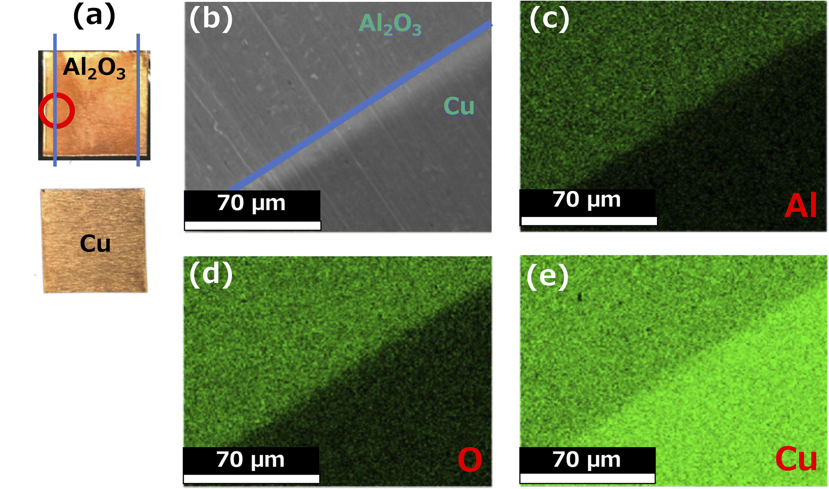 | ||
| Fig. 1 (a) Optical image, (b) SEM image, and (c) element distribution of Al, (c) O, and (d) Cu of the Al2O3 thin film surface after 2 h of PLD experiment. | ||
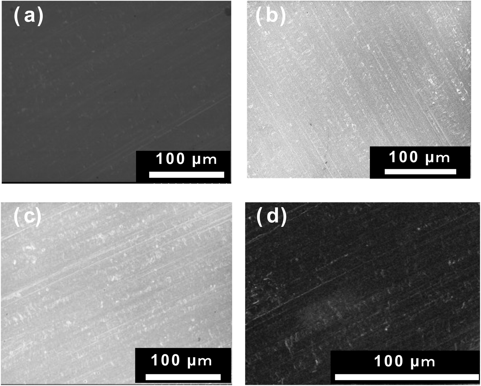 | ||
| Fig. 2 Surface SEM images of the Al2O3 thin films after 1, 2, and 3 h of ablation. (a) 1, (b) 2, and (c) 3 h, as well as that of the (d) Cu substrate. | ||
Fig. 3 shows the cross-sectional bright-field TEM image and nanobeam electron diffraction pattern of the Al2O3 thin film deposited for 3 h. In Fig. 3a, the dark grey layer indicated by the blue arrow is the Al2O3 thin film, the black layer on the left is the Cu foil, and the part shown by the red circle is the position of nanobeam irradiation. The thickness of the Al2O3 thin film deposited for 3 h was found to be 82 nm. No contrast was observed in the Al2O3 thin-film layer, indicating that the Al2O3 deposit was dense and uniform. In addition, a very smooth surface was observed, which is consistent with the results in Fig. 2. This also supports the smooth surface morphology of the Al2O3 film. In the electron diffraction image in Fig. 3b, there are no clear diffraction spots or rings, and only a halo pattern can be seen, suggesting that the Al2O3 thin film has an amorphous structure.
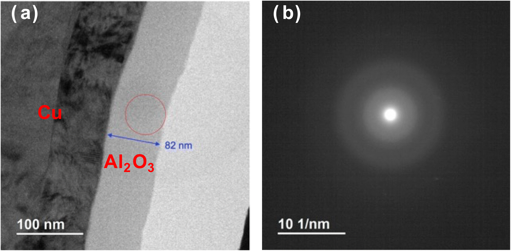 | ||
| Fig. 3 (a) Cross-sectional bright-field TEM image and (b) nanobeam electron diffraction pattern of the Al2O3 thin film after 3 h of ablation. | ||
Fig. 4a–c shows the Al 2s, O 1s, and Cu 2p3/2 XPS spectra of the Al2O3 thin film deposited on the Cu foil for 1 h, and the element concentration ratios in the depth direction of the Al2O3 thin films deposited for 1 and 3 h are shown in Fig. 4d and e, respectively; these were calculated from the peak areas and ionisation cross-sections of the Al 2s, O 1s, and Cu 2p3/2 spectra. For these measurements, sample etching was performed with an Ar+ gun and the depth direction was examined. Clear peaks corresponding to the Al 2s, O 1s, and Cu 2p3/2 orbitals were observed, and the Al2O3 thin film thicknesses were determined from the etching rate and the etching cycle number at which the Cu 2p3/2 peak derived from the Cu foil appeared. The films prepared using 1, 2, and 3 h of ablation showed an approximate Al:O ratio of 2:3, indicating the successful synthesis of alumina (Al2O3), that is, the target material. For the sample deposited for 1 h, only O and Al derived from Al2O3 film were observed in the initial stages of etching. And then, the Cu concentration for the Cu substrate increased after 4 min, and the concentration of O decreased. This is because the peak positions of Al 2s and Cu 3s are close to one another and are, thus, overlapped. For the sample prepared by 3 h of ablation, the Cu concentration increased from 21 min. Therefore, considering an etching rate of 4 nm min−1, the film thickness was approximately 15 nm thick after 1 h of ablation and approximately 80 nm thick after 3 h of ablation.
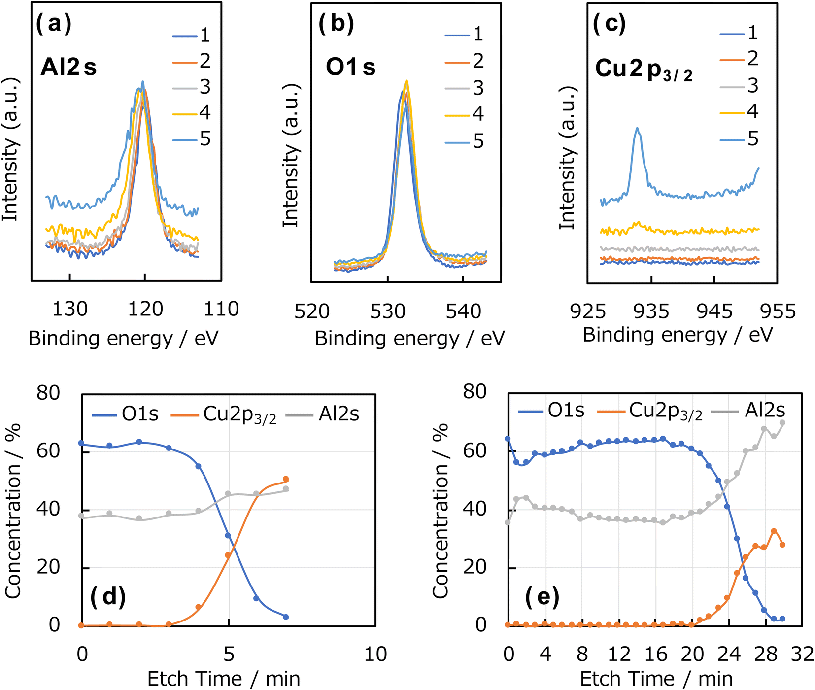 | ||
| Fig. 4 (a) Al 2s, (b) O 1s, and (c) Cu 2p3/2 photoelectron spectra of Al2O3 thin film deposited on Cu foil for 1 h. Element concentration ratios in the depth direction of Al2O3 thin films deposited for (d) 1 and 3 h. Numbers in the graph indicate the number of scan cycles. | ||
Subsequently, the coulombic efficiency was evaluated by charge–discharge tests using the Al2O3-deposited samples and uncoated Cu foils as electrodes. Fig. 5 shows the charge–discharge curves of the Al2O3-deposited electrode and uncoated Cu electrode. The Al2O3-deposited electrodes were prepared for 1 and 3 h. The inset shows an enlarged view of the initial deposition reaction curve for each electrode. During cycling, for each electrode, a spike corresponding to nucleation was observed during the initial lithium deposition reaction, followed by a plateau region corresponding to continuous deposition. The uncoated Cu electrode showed a nucleation overpotential of −0.12 V, whereas those prepared by ablation for 1 and 3 h had nucleation overpotentials of −0.21 and −0.24 V, respectively. Thus, the Al2O3-coating increases the nucleation overpotential, which should be attributed to an increase in the electron supply resistance with a larger thickness of the Al2O3 layer with insulating nature. In addition, the charge–discharge tests of the uncoated Cu electrode contain a sloped region until the peak corresponding to the initial deposition reaction, whereas this sloped region almost disappeared in the tests of the Al2O3-coated Cu electrode. This suggests that side reactions (such as the decomposition of the electrolyte components) other than the deposition of lithium (that is, the forward reaction) were suppressed. In addition, after the initial deposition reaction, a plateau corresponding to the dissolution reaction was observed, and a sharp increase in the overpotential was seen at around 0.5 mA h. Subsequently, a reversible deposition–dissolution reaction was observed, and no significant change in the reaction overpotential and the shape of charge–discharge curves were observed with respect to the presence, absence, or thickness of the Al2O3 thin film until 60th cycle. Fig. 5d shows the change in the coulombic efficiency on cycling obtained from the charge–discharge tests of the uncoated and coated electrodes. Three data sets were presented for the uncoated and 1 h Al2O3-coated Cu electrodes, and two sets were shown for the 3 h Al2O3-coated Cu electrodes, respectively. A clear superiority of Al2O3 coating is observed. For the uncoated Cu electrode (black line), the maximum coulombic efficiency was approximately 87% and maintained above 80% for 100 cycles, subsequently showing a sharp drop. On the other hand, the sample prepared by ablation for 1 h (green line) exhibited a maximum was approximately 93% and maintained above 80% for up to 150 cycles. The sample prepared by ablation for 3 h also showed better cycling behaviour than the uncoated Cu electrode, confirming that the Al2O3 coating is effective in improving the coulombic efficiency and cycling characteristics.
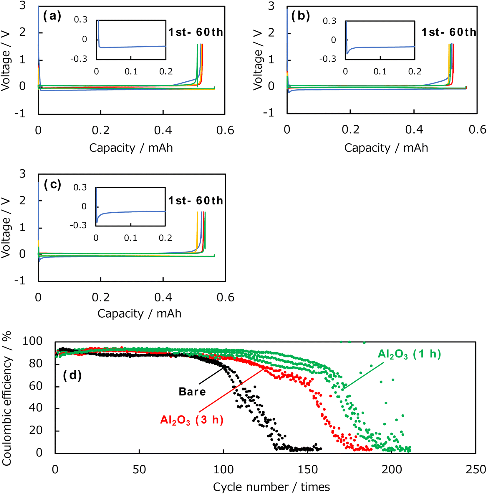 | ||
| Fig. 5 Charge–discharge curves of the (a) uncoated Cu electrode, (b) 1 h Al2O3-coated Cu electrode, and (c) 3 h Al2O3-coated Cu electrode. (d) Cycle dependence of the coulombic efficiencies for the bare and Al2O3-coated Cu electrodes. The deposition and dissolution times are 60 min, respectively. | ||
The morphology of the deposited lithium and the SEI formed via side reactions with the electrolyte affect the deposition–dissolution of lithium. Therefore, to clarify how the Al2O3 coating improves the coulombic efficiency and cycling behaviour, the morphologies of the lithium deposits were tracked from the initial stages of the lithium-deposition reaction by SEM observation. For these measurements, the uncoated Cu electrode and that prepared by ablation of Al2O3 for 1 h were used. The cell configuration and the electrolyte were the same as those used to evaluate the coulombic efficiency and cycling characteristics. Briefly, after the deposition of metallic lithium on each electrode for 1, 6, and 60 min, the cell was disassembled in a glove box, the electrodes were washed with dimethyl carbonate (DMC), and SEM observation was carried out. Fig. 6a and b show the surface SEM images of the uncoated Cu electrode after 1 min of electrodeposition. In the 5000× magnified image shown in Fig. 6a, tiny, white dot-like lithium nuclei can be seen on the electrode surface. In the 20000× image shown in Fig. 6b, lithium nuclei of about 0.2 μm in size can be seen uniformly distributed over the entire electrode surface. Fig. 6c and d show SEM images of the surface of the uncoated Cu electrode after 6 min of electrodeposition; as shown, lithium having a thickness of about 0.2 μm had grown from the tiny lithium nuclei, forming three-dimensional needle-like shapes in the direction perpendicular to the electrode surface. Further, these structures were entangled and covered the electrode surface. For the uncoated Cu electrode, tiny lithium nuclei were deposited uniformly over the entire surface and then grew in three-dimensions. Fig. 6e and f show the surface SEM images of the uncoated Cu electrode after 60 min of electrodeposition; as shown, entangled needle-like deposits were accumulated in layers. In other words, on the uncoated Cu electrode, we found that, following the formation of uniform and tiny lithium nuclei over the entire electrode, the lithium grew three-dimensionally in needle-like shapes. In contrast, on the Al2O3-coated Cu electrode treated by 1 h of PLD, a unique morphology was formed. Fig. 7a–c show surface SEM images at different magnifications of this electrode after 1 min of electrodeposition. As shown, deposited lithium was observed on the Al2O3 film, and this is the first report of this observation. In addition, the deposited lithium was in clusters of 10–20 μm size, forming island-like shapes. Further, there was a region of the electrode surface with no deposits. Thus, in the initial stages of the lithium-deposition reaction, larger lithium formed partly with island shapes on the surface of the Al2O3-coated Cu electrode. Generally, although a larger nucleation overpotential results in the formation of smaller and uniform lithium nuclei on the electrode surface,39,40 the opposite lithium deposition manner with dense and island shapes was observed on the Al2O3-coated Cu electrodes as shown in Fig. 5. One possibility is that the charge transfer process on the Al2O3-coated Cu electrode is suppressed and surface diffusion of Li+ is promoted by the increase in the electron supply resistance with a larger thickness of the Al2O3 layer with insulating nature. This should result in the large lithium with an island shape for the Al2O3-coated Cu electrode, although the nucleation overpotential increase. Notably, this metallic lithium is deposited on the Al2O3 film. Fig. 7d–f show the SEM images at different magnifications of the 1 h PLD sample after 6 min of electrodeposition. As shown, the island-shape lithium was scattered, but the gaps between island-shape lithium are narrower, and the number of island-shape lithium is greater than that observed after 1 min of electrodeposition. The high-magnification SEM image (Fig. 7f) also shows that the islets grow in two-dimensions across the surface of the Al2O3-coated Cu electrode. Fig. 7g–i show the surface SEM images at different magnifications of the same sample after 60 min of electrodeposition. As shown, the lithium grew further across the electrode surface, and had a dense and smooth morphology having a small surface area and formed of large clusters. The large/plate-like lithium ensures sufficient contact with the underlying Al2O3-coated electrode, unlike needle lithium with partial contact. This leads to a uniform path for electronic conduction between the Al2O3-coated Cu electrode and the deposited lithium.
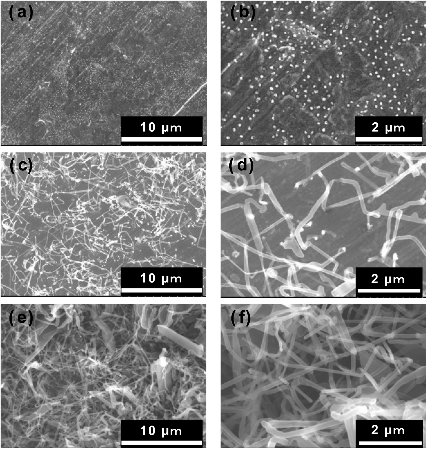 | ||
| Fig. 6 Surface SEM images of uncoated Cu electrode after electrodeposition: (a and b) after 1 min, (c and d) 6 min, and (e and f) 60 min of electrodeposition. | ||
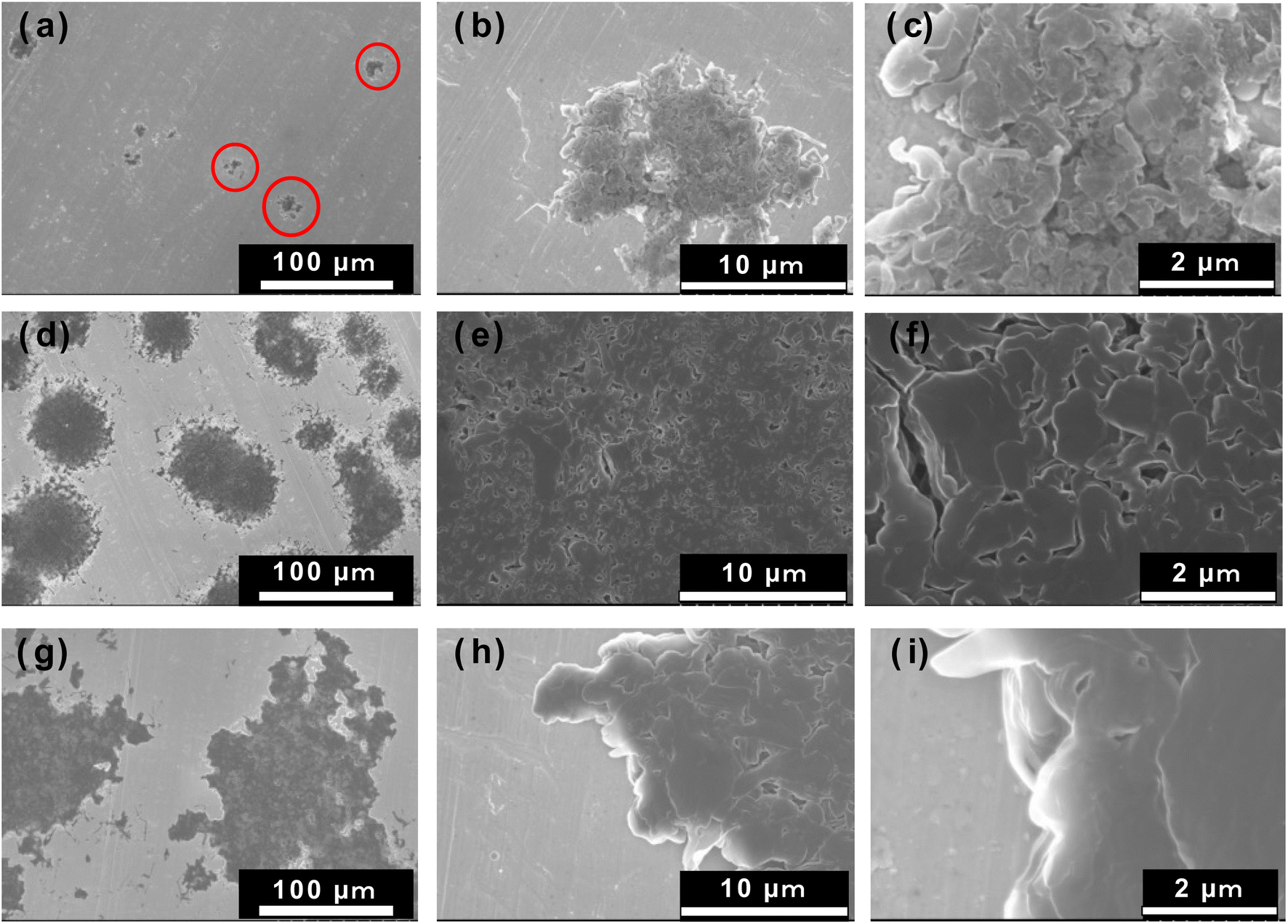 | ||
| Fig. 7 Surface SEM images of Al2O3-coated Cu electrode (1 h PLD) after electrodeposition: (a–c) after 1 min, (d–f) 6 min, and (g–i) 60 min of electrodeposition. | ||
The lithium deposited on the uncoated Cu and Al2O3-coated Cu electrodes were needle-like and dense/smooth clusters, respectively. Next, we observed the samples after the corresponding dissolution reaction using SEM. Fig. 8 shows the photographs and SEM images of an uncoated Cu electrode and the 1 h PLD Al2O3-coated Cu electrode after 60 min of lithium electrodeposition, followed by 60 min of dissolution reaction. On the uncoated Cu electrode, black needle-like porous lithium can be seen on the electrode surface even after the dissolution reaction, suggesting that the needle-shaped lithium deposits remained undissolved and accumulated during each deposition–dissolution cycle. In contrast, the SEM images of the Al2O3-coated Cu electrode showed no black deposits, indicating that most of the deposited clustered lithium was dissolved. However, the SEM images do reveal the presence of a small number of lithium clusters. These results suggest that the lithium deposition–dissolution reaction is more efficient on the Al2O3-coated Cu electrode than on the uncoated Cu electrode. Fig. 9 shows the surface SEM and EDX images for the 1 h PLD Al2O3-coated Cu electrode after the fifth dissolution reaction. A small amount of lithium clusters was observed, indicating that most of the deposited lithium was dissolved even at the fifth cycle. Notably, there are no significant changes in the surface morphology of the Al2O3 layer compared to before the reaction and after the first cycle. Furthermore, the signals derived from Cu and Al (including SEI components of C, O, and F) elements were homogeneously distributed on the surface. If the Al2O3 layer reacts with the deposited lithium, morphological changes and inhomogeneous distribution of chemical composition should occur. Therefore, it is considered that Al2O3 has not reacted in the analysis for the present study. This result also emphasises that the deposited lithium form dense and smooth two-dimensional lithium clusters on the Al2O3 thin film surface not under the Al2O3 layer. If the lithium was deposited under the Al2O3 layer; between the Al2O3 layer and Cu electrode, the Al2O3 layer should be broken by the stress generated at the deposition reaction of lithium. This is not supported by our experimental data. Thus, it is believed that lithium is deposited on Al2O3 thin films during the deposition/dissolution reaction.
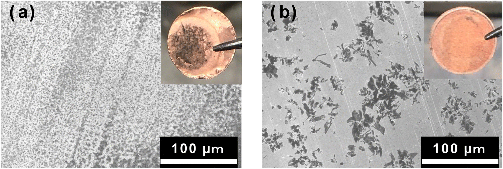 | ||
| Fig. 8 Surface photographs and SEM images of (a) uncoated Cu electrode and (b) Al2O3-coated Cu electrode (1 h PLD) after deposition/dissolution reactions for 60 min each. | ||
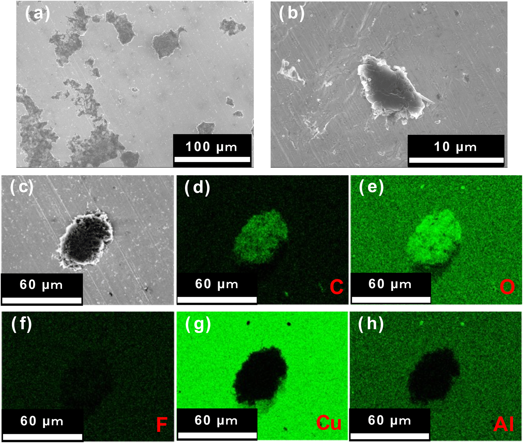 | ||
| Fig. 9 Surface (a–c) SEM images and (d) element distribution of C, (e) O, (f) F, (g) Cu, and (h) for the Al2O3-coated Cu electrode (1 h PLD) after the fifth deposition/dissolution reactions for 60 min each. | ||
Next, depth-resolved XPS measurements were performed to clarify the composition and thickness of the SEI formed on the uncoated Cu and Al2O3-coated (1 h) electrodes. Fig. 10a and b show the C 1s and F 1s spectra, respectively, of the SEI film formed on the uncoated Cu electrode, and Fig. 10c and d show the corresponding spectra for the coated electrode. The etching was performed with an Ar+ gun, and the spectral changes in the depth direction were investigated. Concerning the C 1s photoelectron spectra in Fig. 10a and c, peaks corresponding to Li2CO3 and organic components were observed near 290 and 284 eV in the spectrum of the uncoated Cu electrode. In the spectrum of the Al2O3-coated Cu electrode, the peak corresponding to Li2CO3 at approximately 290 eV was not observed, although the peak corresponding to organic components near 284 eV was observed. These results suggest that the Al2O3 coating suppresses the formation of Li2CO3 arising from the decomposition of the electrolyte. In addition, we found that the C 1s peak disappeared from the spectrum of the uncoated electrode after 41 etching cycles, whereas the same peak disappeared after only 6 etching cycles from the spectrum of the Al2O3-coated Cu electrode, indicating that the SEI layer was thinner than that formed on the uncoated electrode. In the F 1s spectra of the uncoated and coated Cu electrodes in Fig. 10b and d, respectively, there are peaks at 684 and 686 eV, respectively, for the Al2O3-coated Cu electrode. Thus, this characteristic peak is affected by the presence of Al2O3 and suggests that different F-containing compounds are produced during SEI formation; that is, the presence of the Al2O3 coating altered the composition of the SEI. In addition, the depth-dependent F 1s XPS results obtained after Ar+ etching revealed that the spectrum of the uncoated electrode contained F 1s peaks until 31 etching cycles, whereas the peaks disappeared from the spectrum of the Al2O3-coated Cu electrode after 11 cycles, which again suggests that the Al2O3 coating suppresses SEI formation. Fig. 11 shows the element concentration ratios of the SEI film in the depth direction. The element ratios were calculated from the peak areas and ionisation cross-sections of the Li 1s, C 1s, O 1s, Cu 2p3/2, F 1s, and Al 2s photoelectron spectra. In the spectrum of the uncoated Cu electrode shown in Fig. 11a, peaks consistent with Li, C, O, and F, which are considered to be SEI components, were observed up to the 30th cycle. Thereafter, the Cu concentration increased, and, by the 40th cycle, the peaks corresponding to the SEI components (Li, C, O, and F) disappeared, leaving Cu as the only observable element. In contrast, in the spectrum of the Al2O3-coated Cu electrode shown in Fig. 11b, the presence of Al in the underlying Al2O3 film was confirmed before Ar+ etching, and the peaks corresponding to the SEI components (C, O, and F) almost disappeared after the 5th etching cycle. Therefore, these results indicate that thinner SEI was formed on the Al2O3-coated Cu electrode than on the uncoated Cu electrode.
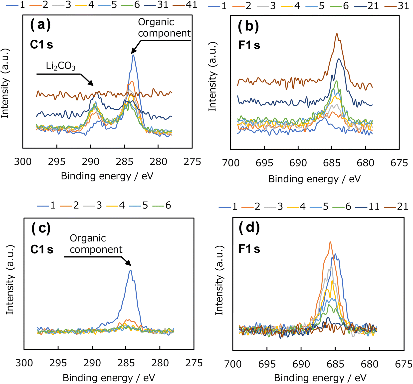 | ||
| Fig. 10 (a) C 1s and (b) F 1s photoelectron spectra of SEI film formed on Cu electrode. (c) C 1s and (d) F 1s photoelectron spectra of the SEI film formed on Al2O3-coated Cu electrode. Numbers in the graph indicate the number of cycles of the measurement scan, which means how many times it has been measured. We conducted the XPS measurement, followed by Ar+ etching applied to the sample to get the information in the depth direction. This combination means one cycle in the XPS experiment. | ||
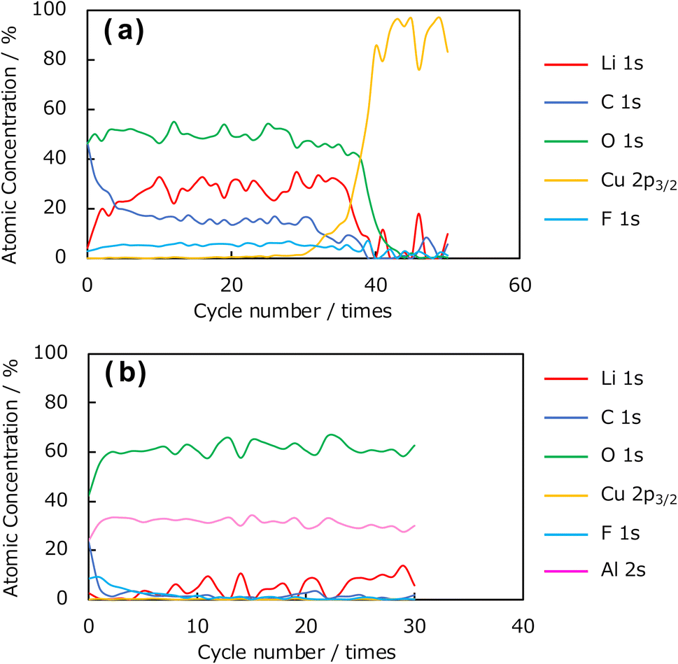 | ||
| Fig. 11 Element concentration ratio in the depth direction of SEI films formed on (a) uncoated and (b) Al2O3-coated Cu electrodes. SEI film was formed at +20 mV (vs. Li/Li+) in the first electroreduction process. | ||
The main aim of this study was to understand the improvement in lithium deposition–dissolution behaviour, as well as its mechanism, that is observed by the coating of an artificial Al2O3 SEI using electron microscopy observation and XPS measurements of the initial stages of the lithium deposition–dissolution reaction. Previous studies have focused on optimising the deposition–dissolution behaviour by adjusting the thickness of the coating Al2O3 thin film. The morphological analysis of the electrode surface before and after hundreds of cycles with consideration of the known bulk properties of Al2O3 has provided little clear experimental evidence to support the improvement of the characteristics of the deposition–dissolution reaction. There have been no attempts to elucidate the mechanism by following the reaction from the initial nucleation of lithium and its subsequent accumulation, as reported in this study. Our investigation of the morphology of the lithium deposited in conventional LiPF6 EC/DEC electrolyte by electron microscopy revealed that uniform lithium nucleation occurred on the uncoated Cu electrode, followed by the deposition of needle-like lithium through three-dimensional growth, as well as the formation of a large amount of undissolved porous metallic lithium after dissolution cycles. In contrast, on the Al2O3-coated Cu electrode, we found that lithium was deposited on the Al2O3 thin film rather than underneath it. In addition, after the deposition of dense and smooth clusters of lithium on the Al2O3 thin film, the lithium grew two-dimensionally across the electrode surface. The large/plate-like lithium ensures sufficient contact with the underlying Al2O3-coated electrode, unlike needle lithium with partial contact. This leads to a uniform electron conduction pathway to the Cu electrode via amorphous Al2O3 film. Thus, a more uniform dissolution reaction, an increase in the amount of solute were achieved for the Al2O3-coated electrode. Furthermore, the suppression of electrolyte decomposition between the lithium and organic electrolyte as a result of the small surface area of deposited lithium. As a result, the coulombic efficiency and cycling behaviour of the coated electrode was enhanced compared to that of the uncoated Cu electrode. Furthermore, the presence of Al2O3, which has low electron conductivity with respect to Cu, suppresses the supply of electrons to the electrode surface, reducing the amount of electrolyte decomposition and suppressing SEI formation, and this has a positive effect on the deposition–dissolution characteristics. However, lithium is deposited on the Al2O3 thin film, and, thus, Li grows on Li in subsequent cycles in the same way as that on the uncoated electrode. Consequently, reactions with the electrolyte cannot be completely suppressed. Therefore, there was no dramatic improvement in the cycling characteristics.
In summary, we have clarified the manner in which lithium is deposited on Al2O3 thin films, as well as why the lithium deposits form dense and smooth clusters. Hypothetically, if Al2O3 develops weak electronic conductivity by amorphisation, the Li+ + e− → Li reduction process occurs. Low conductive nature should suppress the charge transfer process and promote surface diffusion of Li+ on the Al2O3-coated Cu electrode. In addition, the high affinity of Al2O3 with Li+ could guide the Li+ ion flux and reduce localized current on the electrode.41,42 These lead to lithium deposition on the thin films as well as the formation of two-dimensional plate-like deposits. Going forward, the mechanism should be investigated further, and the optimal form of the inorganic artificial SEI including chemical composition, thickness, and so on should be clarified, and we are currently working on a detailed analysis towards this.
Conclusion
In this study, we aimed to elucidate the factors responsible for the enhancement in characteristics of lithium metal anode after coating with an Al2O3 thin film as an artificial SEI, specifically, the suppression of undesirable reactions such as lithium dendrite formation and electrolyte decomposition. SEM observation revealed that the Al2O3 thin films prepared by PLD were smooth and glossy after ablation for 1, 2, and 3 h. Further, EDX analysis confirmed the formation of Al2O3. In addition, TEM observations revealed that the Al2O3 thin film was amorphous, and the film thickness after 3 h of ablation was approximately 82 nm. The XPS measurements of the Al2O3 thin films showed that the composition ratio of Al2O3, the target material, was maintained for all durations (1, 2 and 3 h) of Al2O3 ablation. Using coin cells, we performed charge–discharge measurements to evaluate the coulombic efficiency and cycling behaviour of the coated (1 and 3 h) and uncoated electrodes, and the results showed that both Al2O3-coated electrodes had higher coulombic efficiencies and enhanced cycling characteristics than the uncoated Cu electrode. In particular, the Cu electrode treated by 1 h of PLD exhibited the best characteristics. To clarify the differences in electrochemical performance, we observed the lithium morphology at the initial stage of the lithium deposition reaction, as well as the subsequent dissolution morphology. Although needle-like lithium grew three-dimensionally on the uncoated Cu electrode, lithium was first deposited on the Al2O3 thin film surface on the 1 h PLD Al2O3-coated electrode, then formed dense and smooth two-dimensional lithium clusters. The analysis of the coating composition and thickness by XPS revealed that SEI formation arising from electrolyte decomposition was suppressed by the Al2O3 coating. On the basis of these results, the coulombic efficiency and cycling behaviour are enhanced by the addition of an Al2O3 coating because of the formation of less “dead Li,” which separates the lithium from the electrode and, removing lithium from the reaction system. In addition, the Al2O3 coating suppressed side reactions with the electrolyte to a greater extent than for the uncoated Cu electrode. As a result, flat clusters of lithium were deposited on the Al2O3 thin film.Conflicts of interest
There are no conflicts of interest to declare.References
- D. Lin, Y. Liu and Y. Cui, Nat. Nanotechnol., 2017, 12, 194–206 CrossRef CAS PubMed.
- P. G. Bruce, S. A. Freunberger, L. J. Hardwick and J. M. Tarascon, Nat. Mater., 2012, 11, 19–29 CrossRef CAS PubMed.
- R. Fang, S. Zhao, Z. Sun, D. W. Wang, H. M. Cheng and F. Li, Adv. Mater., 2017, 29, 1606823 CrossRef PubMed.
- W. J. Kwak, Rosy, D. Sharon, C. Xia, H. Kim, L. R. Johnson, P. G. Bruce, L. F. Nazar, Y. K. Sun, A. A. Frimer, M. Noked, S. A. Freunberger and D. Aurbach, ACS Appl. Mater. Interfaces, 2020, 120, 6626–6683 CAS.
- J. He and A. Manthiram, Energy Storage Mater., 2019, 20, 55–70 CrossRef.
- N.-S. Choi, Z. Chen, S. A. Freunberger, X. Ji, Y.-K. Sun, K. Amine, G. Yushin, L. F. Nazar, J. Cho and P. G. Bruce, Angew. Chem., 2012, 124, 10134–10166 CrossRef.
- H. Kim, G. Jeong, Y. U. Kim, J. H. Kim, C. M. Park and H. J. Sohn, Chem. Soc. Rev., 2013, 42, 9011–9034 RSC.
- C. Yang, K. Fu, Y. Zhang, E. Hitz and L. Hu, Adv. Mater., 2017, 29, 1701169 CrossRef PubMed.
- E. Peled, D. Golodnitsky and J. Penciner, in Handbook of Battery Materials, ed. J. O. Besenhard, John Wiley & Sons, Ltd, 1998, pp. 419–456 Search PubMed.
- E. Peled and S. Menkin, J. Electrochem. Soc., 2017, 164, A1703–A1719 CrossRef CAS.
- M. D. Tikekar, S. Choudhury, Z. Tu and L. A. Archer, Nat. Energy, 2016, 1, 16114 CrossRef CAS.
- X.-B. Cheng, R. Zhang, C.-Z. Zhao and Q. Zhang, Chem. Rev., 2017, 117, 10403–10473 CrossRef CAS PubMed.
- A. Kushima, K. P. So, C. Su, P. Bai, N. Kuriyama, T. Maebashi, Y. Fujiwara, M. Z. Bazant and J. Li, Nano Energy, 2017, 32, 271–279 CrossRef CAS.
- M. Yang, J. Li and A. Li, Nat. Commun., 2015, 6, 6445 CrossRef CAS PubMed.
- L. L. Lu, J. Ge, J. N. Yang, S. M. Chen, H. Bin Yao, F. Zhou and S. H. Yu, Nano Lett., 2016, 16, 4431–4437 CrossRef CAS PubMed.
- B. Lu, E. Olivera, J. Scharf, M. Chouchane, C. Fang, M. Ceja, L. E. Pangilinan, S. Zheng, A. Dawson, D. Cheng, W. Bao, O. Arcelus, A. A. Franco, X. Li, S. H. Tolbert and Y. S. Meng, ACS Appl. Energy Mater., 2021, 4, 6454–6465 CrossRef CAS.
- K. Yan, H. W. Lee, T. Gao, G. Zheng, H. Yao, H. Wang, Z. Lu, Y. Zhou, Z. Liang, Z. Liu, S. Chu and Y. Cui, Nano Lett., 2014, 14, 6016–6022 CrossRef CAS PubMed.
- Y. Liu, D. Lin, Z. Liang, J. Zhao, K. Yan and Y. Cui, Nat. Commun., 2016, 7, 10992 CrossRef CAS PubMed.
- L. Liu, Y. X. Yin, J. Y. Li, S. H. Wang, Y. G. Guo and L. J. Wan, Adv. Mater., 2018, 30, 1706216 CrossRef PubMed.
- R. Miao, J. Yang, X. Feng, H. Jia, J. Wang and Y. Nuli, J. Power Sources, 2014, 271, 291–297 CrossRef CAS.
- X. Zheng, J. Troughton, N. Gasparini, Y. Lin, M. Wei, Y. Hou, J. Liu, K. Song, Z. Chen, C. Yang, B. Turedi, A. Y. Alsalloum, J. Pan, J. Chen, A. A. Zhumekenov, T. D. Anthopoulos, Y. Han, D. Baran, O. F. Mohammed, E. H. Sargent and O. M. Bakr, Joule, 2019, 3, 1963–1976 CrossRef CAS.
- F. Ding, W. Xu, G. L. Graff, J. Zhang, M. L. Sushko, X. Chen, Y. Shao, M. H. Engelhard, Z. Nie, J. Xiao, X. Liu, P. V. Sushko, J. Liu and J. G. Zhang, J. Am. Chem. Soc., 2013, 135, 4450–4456 CrossRef CAS PubMed.
- W. Li, H. Yao, K. Yan, G. Zheng, Z. Liang, Y. M. Chiang and Y. Cui, Nat. Commun., 2015, 6, 1–8 Search PubMed.
- S. Choudhury and L. A. Archer, Adv. Electron. Mater., 2016, 2, 1500246 CrossRef.
- Y. Liu, S. Xiong, J. Wang, X. Jiao, S. Li, C. Zhang, Z. Song and J. Song, Energy Storage Mater., 2019, 19, 24–30 CrossRef.
- Y. Liu, Q. Liu, L. Xin, Y. Liu, F. Yang, E. A. Stach and J. Xie, Nat. Energy, 2017, 2, 1–10 Search PubMed.
- S. Xu, D. W. McOwen, C. Wang, L. Zhang, W. Luo, C. Chen, Y. Li, Y. Gong, J. Dai, Y. Kuang, C. Yang, T. R. Hamann, E. D. Wachsman and L. Hu, Nano Lett., 2018, 18, 3926–3933 CrossRef CAS PubMed.
- L. Chen, Y. Li, S. P. Li, L. Z. Fan, C. W. Nan and J. B. Goodenough, Nano Energy, 2018, 46, 176–184 CrossRef CAS.
- L. Wang, Q. Wang, W. Jia, S. Chen, P. Gao and J. Li, J. Power Sources, 2017, 342, 175–182 CrossRef CAS.
- B. Zhu, Y. Jin, X. Hu, Q. Zheng, S. Zhang, Q. Wang and J. Zhu, Adv. Mater., 2017, 29, 1603755 CrossRef PubMed.
- H. Zhang, X. Liao, Y. Guan, Y. Xiang, M. Li, W. Zhang, X. Zhu, H. Ming, L. Lu, J. Qiu, Y. Huang, G. Cao, Y. Yang, L. Mai, Y. Zhao and H. Zhang, Nat. Commun., 2018, 9, 3729 CrossRef PubMed.
- L. Shen, P. Shi, X. Hao, Q. Zhao, J. Ma, Y. B. He and F. Kang, Small, 2020, 16, 2000699 CrossRef CAS PubMed.
- G. M. Hobold, J. Lopez, R. Guo, N. Minafra, A. Banerjee, Y. Shirley Meng, Y. Shao-Horn and B. M. Gallant, Nat. Energy, 2021, 6, 951–960 CrossRef CAS.
- R. Xu, X. B. Cheng, C. Yan, X. Q. Zhang, Y. Xiao, C. Z. Zhao, J. Q. Huang and Q. Zhang, Matter, 2019, 1, 317–344 CrossRef.
- A. C. Kozen, C. F. Lin, A. J. Pearse, M. A. Schroeder, X. Han, L. Hu, S. B. Lee, G. W. Rubloff and M. Noked, ACS Nano, 2015, 9, 5884–5892 CrossRef CAS PubMed.
- E. Kazyak, K. N. Wood and N. P. Dasgupta, Chem. Mater., 2015, 27, 6457–6462 CrossRef CAS.
- L. Chen, J. G. Connell, A. Nie, Z. Huang, K. R. Zavadil, K. C. Klavetter, Y. Yuan, S. Sharifi-Asl, R. Shahbazian-Yassar, J. A. Libera, A. U. Mane and J. W. Elam, J. Mater. Chem. A, 2017, 5, 12297–12309 RSC.
- L. Wang, L. Zhang, Q. Wang, W. Li, B. Wu, W. Jia, Y. Wang, J. Li and H. Li, Energy Storage Mater., 2018, 10, 16–23 CrossRef.
- A. Pei, G. Zheng, F. Shi, Y. Li and Y. Cui, Nano Lett., 2017, 17, 1132–1139 CrossRef CAS PubMed.
- R. Winand, J. Appl. Electrochem., 1991, 21, 377–385 CrossRef CAS.
- J. Wang, H. Wang, J. Xie, A. Yang, A. Pei, C.-L. Wu, F. Shi, Y. Liu, D. Lin, Y. Gong and Y. Cui, Energy Storage Mater., 2018, 14, 345–350 CrossRef.
- C. Jin, O. Sheng, Y. Lu, J. Luo, H. Yuan, W. Zhang, H. Huang, Y. Gan, Y. Xia, C. Liang, J. Zhang and X. Tao, Nano Energy, 2018, 45, 203–209 CrossRef CAS.
| This journal is © The Royal Society of Chemistry 2023 |