A reversible and highly conductive adhesive: towards self-healing and recyclable flexible electronics†
Qiming
Yan
,
Meng
Zhou
and
Heqing
Fu
 *
*
School of Chemistry and Chemical Engineering, Guangdong Provincial Key Lab of Green Chemical Product Technology, South China University of Technology, Guangzhou 510640, P. R. China. E-mail: fuhq@scut.edu.cn; Fax: +86 020 87112047; Tel: +86 020 87114919
First published on 27th April 2020
Abstract
Flexible conductive adhesives are important materials for the next generation of flexible electronic devices. Herein, we prepared a reversible conductive flexible adhesive (RCFA) based on a furan-terminated four-armed polyurethane resin, urea-group-grafted multi-walled carbon nanotubes (urea-g-MWCNTs) and silver nanoparticle decorated multi-walled carbon nanotubes (Ag@MWCNTs). This adhesive has good mechanical robustness, fast self-healing capability under near-infrared (NIR) irradiation and high electrical conductivity under mechanical deformation. At the same time, the fast self-healing and the reinforced electrical conductive mechanisms of RCFA were analyzed. Mechanical tests showed that with the incorporation of 3 wt% urea-g-MWCNTs and 7 wt% Ag@MWCNTs, the ultimate strength and the break strain of RCFA can reach as high as 14.79 MPa and 603%, respectively. Owing to the reversible Diels–Alder reaction and hydrogen bonding interaction, the conductive adhesive exhibited more than 90% self-healing efficiency after 20 min of NIR irradiation. Moreover, the electrical resistivity of RCFA was about 0.15 Ω cm and can be maintained during stretching and bending processes. Finally, we explored the potential applications of the as-prepared RCFA in light emitting diode arrays and radio frequency identification. Our report may open an effective pathway to fabricate reversible conductive flexible adhesives for the next generation of flexible electronic devices.
1. Introduction
In the last few years, there has been extensive research on modern electronic devices, especially flexible electronic devices.1–3 Flexible electronic devices have been used in thin-film electrodes,4–6 flexible transistors,7,8 antenna arrays,9,10 energy-storage devices11,12 and flexible rechargeable batteries.13,14 Connecting materials are important in flexible electronic devices, and good connecting materials need to have good electric conduction, outstanding mechanical compliance, long service time, good adhesion and low curing temperature. Although much attention has been paid to the research of manufacturing flexible electronic devices,15–19 less focus has been on the flexible electrical interconnection. Traditional eutectic Sn/Pb solder has been widely used as an electronic interconnection, and it has many merits in the applications of chip scale package (CSP), surface mounting technology (SMT) and ball grid array (BGA).20–23 However, Sn/Pb solder is usually used to bond a rigid and thermostable substrate instead of forming a flexible interconnection due to the fact that it cannot withstand a high processing temperature (above 250 °C) and undergo mechanical deformation.24,25 A high temperature will damage the flexible film substrates such as polyethylene (PE), poly(ethylene terephthalate) (PET) and polypropylene (PP).26–30 In addition, long-term mechanical deformation can easily lead to failure of the adhesion joint.Recently, considerable attention has been paid to the epoxy-based isotropically conductive adhesive (ICA).31–33 Unfortunately, low electrical conductivity34 (103–105 S cm−1), expensive price35,36 (containing silver flakes or wires) and high rigidity limit its applications. On the other hand, bisphenol-A derivatives and toxic amino-curing agents pose a potential risk to human health.37 Alternatively, UV-curable acrylate is considered to be another feasible ICA, yet its short shelf life caused by free radical oxidation38,39 also limits its widespread use. In addition to the above weakness, these ICAs are usually disposable irreversible thermosetting materials.40 Thus, once electronic devices are damaged, they are hard to repair or disassemble for recycling, resulting in a large amount of e-waste.
Herein, we report a novel and economical approach to fabricate a kind of reversible conductive flexible adhesive (RCFA) that can solve the above problems. The RCFA was prepared by combining furan-terminated four-armed polyurethane (F4PU) resin, urea-grafted multi-walled carbon nanotubes (urea-g-MWCNTs) and silver nanoparticle-coated multi-walled carbon nanotubes (Ag@MWCNTs). By taking advantage of the Diels–Alder (DA) reaction, the RCFA exhibits many fantastic characteristics, including a relatively low curing temperature, excellent mechanical performance, and self-healing and thermal detachable abilities. Additionally, the electrical conductivity of the as-prepared RCFA changes little when it undergoes bending or stretching deformation, and it has good adhesion to various flexible substrates. This RCFA may have good development prospects in flexible electronic devices.
2. Experimental section
2.1 Materials
Isophorone diisocyanate (IPDI) and 1,6-hexamethylene diisocyanate (HDI) were purchased from Wanhua Chemical Reagent Co., Ltd. Poly(tetramethylene ether)glycol (PTMEG 2000, Mn = 2000 g mol−1) was obtained from Nanjing STIN and used after drying under vacuum at 120 °C for 2 h. Glycidol (98%) and 2-(methylamino)ethanol (99%) were bought from Aladdin Chemical Co., Ltd. Furfuryl alcohol (FA, 99%), bismaleimide (BMI, 96%) and silver acetate (99%) were purchased from Adamas Reagent Co., Ltd. Pristine multi-walled carbon nanotubes and hydroxyl grafted multi-walled carbon nanotubes (outer diameter: >50 nm) were purchased from Nanjing XFNANO Materials Technology Co., Ltd. Ethanol (EtOH, 99.9%), ethyl acetate (EA, 99.8%), tetrahydrofuran (THF, 99.5%), dibutyltin dilaurate (DBTDL, 95%), 1-butanamine (99%) and N,N-dimethylformamide (DMF, 99.5%) were provided by Shanghai Tansoole and used as received.2.2 Synthesis of furan-terminated four-armed polyurethane resin
F4PU resin was synthesized according to the following procedure. First, IPDI (5 g, 22.5 mmol) was reacted with FA (2.2 g, 22.5 mmol) at 60 °C under a nitrogen atmosphere for 4 h to obtain the furan-based blocking agent. Second, PTMEG 2000/EA (20 g/10 g) was dropwise added into HDI/EA (1.93 g/5 g) at 75 °C and stirred for 3 h. Then, glycidol (0.23 g) was added and reacted at 75 °C for 3 h. In order to obtain a four-armed structure, EtOH/2-(methylamino)ethanol (15 g/0.23 g) was added into the above resultant solution and left for another 12 h at 80 °C. After that, the mixture solution was dried under vacuum at 80 °C for 12 h to obtain the four-armed hydroxyl-terminated polyurethane prepolymer. Third, the four-armed hydroxyl-terminated prepolymer (15 g) was redissolved in EA (50 g) and then reacted with the furan-based blocking agent (1.29 g) at 75 °C for 4 h. Finally, the above solution was dried under vacuum at 70 °C overnight and the F4PU resin was obtained.2.3 Preparation of Ag@MWCNTs and urea-g-MWCNTs
Ag@MWCNTs were prepared according to the reported method.41 First, 500 mg of MWCNTs was added into 100 mL of DMF solution and dispersed by ultrasound for 1 h to form a homogeneous solution. Then, 1 g of silver acetate was added into the above solution and dispersed by ultrasound for another 1 h. The obtained mixture solution was stirred for 12 h at 30 °C. After the reaction was completed, the mixture solution was centrifuged at 12![[thin space (1/6-em)]](https://www.rsc.org/images/entities/char_2009.gif) 000 rpm and then washed with deionized water five times to remove the excess silver acetate on the surface of the nanoparticles. The as-prepared Ag@MWCNTs were then dried under vacuum at 50 °C for 24 h.
000 rpm and then washed with deionized water five times to remove the excess silver acetate on the surface of the nanoparticles. The as-prepared Ag@MWCNTs were then dried under vacuum at 50 °C for 24 h.
In order to prepare urea-g-MWCNTs, OH-g-MWCNTs (0.5 g, 0.59 mmol OH, 1.0 eq.) were dispersed by ultrasound in 100 mL of THF solution. HDI (0.5 g, 2.98 mmol, 5.0 eq.) and DBTDL (3 μL) were added into the above mixture solution and stirred at 75 °C for 8 h, then cooled to room temperature. Thereafter, 1-butanamine (0.4 g, 5.47 mmol, 9 eq.) was slowly dropwise added into the above mixture and reacted for another 1 h. The resultant product was treated by washing with THF and centrifuged at 12![[thin space (1/6-em)]](https://www.rsc.org/images/entities/char_2009.gif) 000 rpm repeatedly. Finally, urea-g-MWCNTs were dried under vacuum at 50 °C for 24 h.
000 rpm repeatedly. Finally, urea-g-MWCNTs were dried under vacuum at 50 °C for 24 h.
2.4 Fabrication of reversible conductive flexible adhesive
F4PU resin (10 g) and BMI (0.48 g) were first added into THF (100 mL) and ultrasonically stirred to obtain a uniform solution. Then, urea-g-MWCNTs were dispersed in the mixture under ultrasound for 1 h. Finally, Ag@MWCNTs were added into the above mixture solution and ultrasonicated for another 1 h. The compositions of the RCFA samples are listed in Table 1, coded as RCFAx, where x ranged from 1 to 4 according to the loading content of modified MWCNTs. The obtained RCFA was poured into a PTFE mold or adhered on the substrate under vacuum at room temperature for 12 h to remove THF. And the curing process was conducted at 50 °C for 48 h.| Samples | Weight (g) | Loading content (wt%) | T g (°C) | ||||
|---|---|---|---|---|---|---|---|
| F4PU resins | BMI | Urea-g-MWCNTs (10−2) | Ag@MW CNTs (10−2) | Urea-g-MWCNTs | Ag@MWCNTs | ||
| RCFA0 | 10.00 | 0.48 | 0 | 0 | 0 | 0 | −5.4 |
| RCFA1 | 10.00 | 0.48 | 16.59 | 38.63 | 1.50 | 3.50 | −1.3 |
| RCFA2 | 10.00 | 0.48 | 34.99 | 81.55 | 3.0 | 7.0 | 2.6 |
| RCFA3 | 10.00 | 0.48 | 55.54 | 129.52 | 4.5 | 10.5 | 6.7 |
| RCFA4 | 10.00 | 0.48 | 78.65 | 183.41 | 6.0 | 14.0 | 11.6 |
2.5 Characterization methods
Fourier transform infrared (FTIR) spectra were recorded using a Bruker Vertex FTIR spectrometer. 1H NMR spectra were obtained using a Bruker 400M instrument. X-ray diffraction (XRD) measurement was conducted using a Bruker D8 ADVANCE diffractometer with Cu Kα radiation (scanning rate: 1.0° min−1, 2θ: 15–85°). X-ray photoelectron spectroscopy (XPS) measurement was performed using a Kratos Axis Ulra DLD XPS spectrometer. Scanning electron microscopy (SEM) images were obtained using a Zeiss LEO1530VP scanning electron microscope. To determine the loading amount of Ag nanoparticles on the surface of MWCNTs, atomic absorption spectroscopy (AAS) was used to measure the concentration of silver acetate in DMF solvent before and after mixing with MWCNTs. Differential scanning calorimetry (DSC) analysis was conducted using a NETZSCH DSC-214 instrument at a rate of 10 °C min−1 from −60 °C to 160 °C for heating–cooling cycles under a nitrogen flow. The glass transition temperature (Tg) of RCFA samples was obtained by using TA-Q800 dynamic mechanical analysis (DMA) apparatus. The samples were tested in tensile mode with the temperature increasing from −80 °C to 100 °C. The frequency was 5 Hz with 1% strain. The swelling ratio and gel fraction of RCFA were measured by immersing the cured sample in THF solvent in a closed flask at 30 °C for 24 h. Thereafter, the sample was taken out from the solvent and immediately weighed after wiping off the excess surface THF. The swelling ratio was calculated aswhere m0 is the weight of the cured RCFA sample, and m1 is the weight of the cured RCFA sample after immersing in THF solvent. Afterwards, the RCFA sample was dried under vacuum at 60 °C until its weight was constant. The gel fraction was calculated as
where W0 and Wd are the masses of the cured RCFA sample before swelling and after drying, respectively. The tensile strength was measured using an Instron 5967 Universal Materials Testing Machine at ambient temperature, and the test speed was 5 mm min−1. 180° peeling measurement was performed according to GB/T 2790-1995, as shown in Fig. S3 (ESI†); RCFA was adhered between a polycarbonate substrate (100 mm × 25 mm × 2 mm) and a flexible substrate (250 mm × 25 mm × 0.5 mm), and then heated at 50 °C for 48 h to obtain the final strength adhesion after volatilizing the THF solvent. For the self-healing test, a strip sample was cut into two pieces by a sharp knife, then the fractured surfaces were placed together for heating to 140 °C for 30 min or irradiating under a near-infrared radiation (NIR) laser (808 nm, 7 W). The temperature variation of the sample was measured using an infrared thermometer. The self-healing efficiency was defined as the ratio of tensile strength of the healed sample to that of the original one. Thermogravimetric analysis (TGA) was performed using a TA-Q500 thermogravimetric analyzer under a nitrogen atmosphere at a heating rate of 10 °C min−1 from 30 °C to 600 °C. Dynamic mechanical analysis (DMA) was conducted using a TA-Q800 dynamic mechanical analyzer in tensile mode with a frequency of 5 Hz and a strain change of 1%. The scanning temperature ranged from −80 °C to 150 °C at a heating rate of 3 °C min−1. The stress relaxation test was performed at a strain of 3% and the stress response was recorded over time. The electrical conductivity of RCFA was evaluated by measuring its bulk resistance in samples with specific dimensions. The bulk resistivity ρ was calculated by:
where w, t, and l are the width, thickness and length of the sample, respectively. R was measured using a VICTOR 86E multimeter.
3. Results and discussion
3.1 Characterization of RCFA
The RCFA was prepared from F4PU resin, urea-g-MWCNTs and Ag@MWCNTs. As shown in Fig. 1a, at first, the blocking agent was synthesized, and then a novel dihydroxy-terminated polyurethane-based polyol was prepared through the ring-opening reaction of glycidol with 2-(methylamino)ethanol. Finally, dihydroxy-terminated polyurethane-based polyol was reacted with the blocking agent to obtain F4PU resin (Fig. 1b). The detailed structure information of the blocking agent and F4PU resin is shown in Fig. S1 and S2 (ESI†), respectively.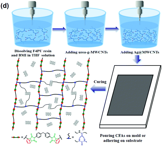 | ||
| Fig. 1 (a) Synthesis of furan-based blocking agent. (b) Synthesis route of F4PU resin. (c) Schematic procedures for the preparation of Ag@MWCNTs and urea-g-MWCNTs. (d) Synthetic procedures of RCFA. | ||
Carbon nanotubes (CNTs) have high conductivity, thermal stability and good mechanical performance; therefore, considerable attention has been paid to them.42 Pure CNTs are difficult to disperse uniformly in polymer matrix and tend to agglomerate due to their π–π stacking effect and high specific surface area. Therefore, CNTs need to be modified so as to improve their dispersity in solvents and polymer matrix. In this study, surface modification of MWCNTs involved Ag@MWCNTs and urea-g-MWCNTs, as shown in Fig. 1c. The XRD patterns of commercial MWCNTs and Ag@MWCNTs are shown in Fig. 2a. From Fig. 2a, we found that the diffraction peaks at 26.03° and 42.78° were assigned to the (002) and (100) planes of MWCNTs, respectively. In the patterns of Ag@MWCNTs, five new peaks appear at 2θ = 37.97°, 44.13°, 64.34°, 77.31° and 81.42° corresponding to the (111), (220), (220), (311) and (222) planes of Ag crystals, which demonstrated that all Ag nanoparticles have a face centered cubic structure. AAS measurement was conducted to determine the loading amount of Ag nanoparticles on the surface of the MWCNTs (Table S1, ESI†). The loading amount of Ag nanoparticles is about 13.2 wt% after reacting for 12 h. Besides, the effects of the loading amount of Ag nanoparticles on the conductivity of MWCNTs were also investigated. With the decoration of Ag nanoparticles, the electrical resistivity of MWCNTs decreased from 1.53 × 10⁻² Ω cm to 0.48 × 10⁻² Ω cm.
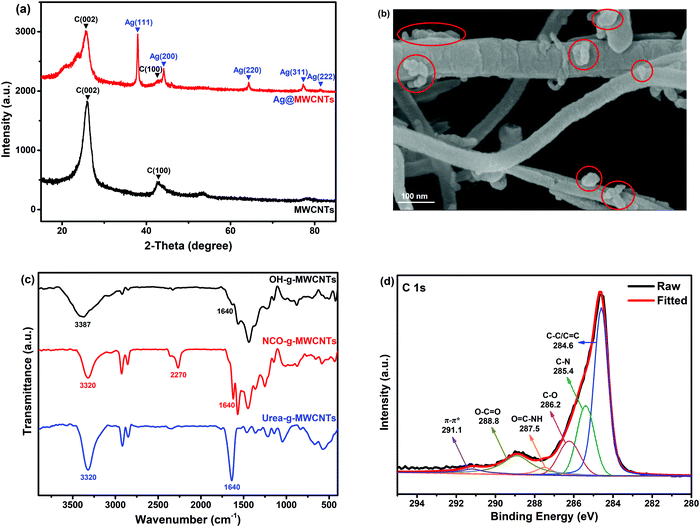 | ||
| Fig. 2 (a) XRD patterns of MWCNTs and Ag@MWCNTs. (b) SEM images of Ag@MWCNTs. (c) FTIR spectra of OH-g-MWCNTs, NCO-g-MWCNTs and urea-g-MWCNTs. (d) XPS elemental survey data of urea-g-MWCNTs. | ||
In order to further observe the surface morphology of Ag@MWCNTs, SEM was employed, as shown in Fig. 2b. From Fig. 2b, it can be found that Ag particles (red circle areas) have been successfully adhered to the surfaces of MWCNTs. This is consistent with the results of the XRD patterns. Besides, urea-g-MWCNTs were characterized by FTIR spectroscopy and XPS. As shown in Fig. 2c, the peak at 3387 cm−1 was ascribed to the hydroxyl group of OH-g-MWCNTs. Two new absorption peaks at 3320 cm−1 and 2270 cm−1 corresponded to –NH– and –NCO groups, respectively, confirming that HDI has been grafted on the surfaces of MWCNTs. From the FTIR spectrum of urea-g-MWCNTs, it can be found that the absorption peak of –NCO group disappeared completely, and the intensity of peaks of –NH– and –NCO groups was enhanced due to the reaction of the –NCO group with 1-butanamine. Fig. 2d shows the XPS results of the MWCNTs. The C 1s spectra of urea-g-MWCNTs were deconvoluted into six component peaks at around 291.1, 288.8, 287.5, 286.2, 285.4 and 284.6 eV, corresponding to π–π* shake-up, O–C![[double bond, length as m-dash]](https://www.rsc.org/images/entities/char_e001.gif) O, O
O, O![[double bond, length as m-dash]](https://www.rsc.org/images/entities/char_e001.gif) C–NH, C–O, C–N and C–C/C
C–NH, C–O, C–N and C–C/C![[double bond, length as m-dash]](https://www.rsc.org/images/entities/char_e001.gif) C, respectively.43,44 These results clearly indicated that urea groups had been successfully grafted on the surfaces of MWCNTs.
C, respectively.43,44 These results clearly indicated that urea groups had been successfully grafted on the surfaces of MWCNTs.
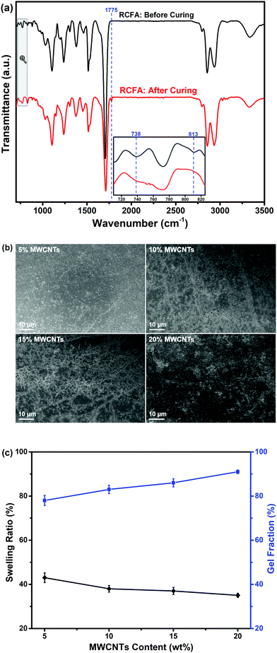
Schematic illustrations of the preparation of RCFA and the formation of cross-linked networks are shown in Fig. 1d. The cross-linked networks of RCFA include two forms: one is the reversible covalent network formed by DA reaction between the furan groups in F4PU resin and maleimide groups in bismaleimide, and the other is the reversible supramolecular network formed by hydrogen bonding interaction between urea-g-MWCNTs and F4PU resin. The completion of the curing process of RCFA was characterized by FTIR spectra, as shown in Fig. 3a. Before curing, the peak at 2270 cm−1 of the –NCO group had disappeared, and new peaks at 738 cm−1 and 813 cm−1 assigned to the furan rings in F4PU resin were observed, suggesting that the four-armed hydroxyl-terminated polyurethane prepolymer had completely reacted with the blocking agent. After curing the RCFA at 50 °C for 48 h, the peaks of furan rings at 738 cm−1 and 813 cm−1 disappeared, and the new peak at 1775 cm−1 ascribed to the DA bond appeared.45,46 These results demonstrated that F4PU resin was successfully reacted with BMI through DA reaction.
As is well known, the distribution of carbon nanotubes in composites has an effect on the mechanical properties, self-healing efficiency and electrical conductivity of nanocomposites. The distribution of urea-g-MWCNTs and Ag@MWCNTs in RCFA was characterized by SEM, as shown in Fig. 3b. It was found that two kinds of modified MWCNTs were well-dispersed in the polymer matrix, even when the loading content of nanofillers reached as high as 20%. Due to the attachment of Ag nanoparticles, the interaction among MWCNTs was weakened. At the same time, the urea groups modified on the MWCNT surface can form hydrogen bonding with F4PU resin. These two factors lead to the uniform distribution of carbon nanotubes in RCFA. Moreover, the equilibrium swelling experiment was conducted to characterize the swelling ratio and gel fraction of RCFA. As shown in Fig. 3c, with increasing content of modified MWCNTs, the gel fraction increased, while the swelling ratio decreased, confirming the formation of denser cross-linked networks.
3.2 Thermal properties of RCFA
Fig. 4a shows DSC curves of RCFA with different contents of modified MWCNTs. The significant DSC peaks of retro-DA (rDA) reaction at 130–155 °C verified the formation of DA bonds during the curing process of RCFA. In addition, there was no change in the endothermic temperature of the rDA reaction with increasing content of the modified MWCNTs. And, it is interesting to note that although PTMEG 2000 was a crystalline polymer, no crystallization peaks were observed in the DSC curves of RCFA. This may be explained by the fact that with the addition of modified MWCNTs, the MWCNTs break the continuity of the polymer matrix and PTMEG 2000 cannot form large and uniform lamellae. As a result, the crystallinity of PTMEG 2000 was destroyed.47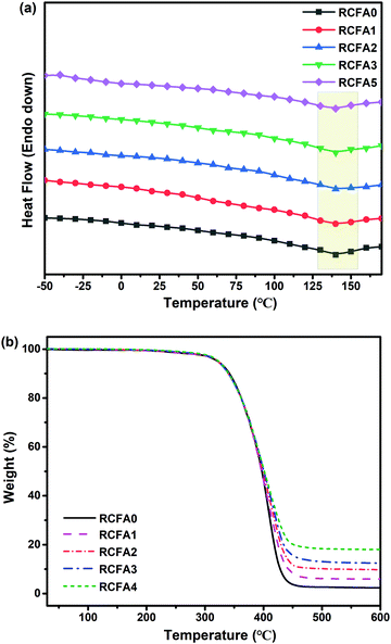 | ||
| Fig. 4 (a) DSC curves of RCFA with different modified MWCNT contents. (b) TGA curves of RCFA with different modified MWCNT contents. | ||
Moreover, the thermal resistance of RCFA was tested by TGA under a nitrogen atmosphere between 30 °C and 600 °C, as shown in Fig. 4b and Table 2. From Fig. 4b and Table 2, it can be seen that the onset decomposition temperature of all RCFA samples was above 310 °C, and the temperature at 5% weight loss (T5%) increased with increasing content of the modified MWCNTs. The temperatures at 10% weight loss (T10%) and 50% weight loss (T50%) of all RCFA samples were above 340 and 395 °C, respectively, suggesting that the prepared RCFA had good thermal stability and similar thermal decomposition behavior. This phenomenon could be attributed to the complete dissociation of DA bonds and hydrogen bonds in RCFA networks over 155 °C. In addition, the char yields of RCFA samples increased with the increase of the modified MWCNT content due to the non-decomposition of MWCNTs and Ag nanoparticles.
| Samples | T 5% (°C) | T 10% (°C) | T 50% (°C) | Char yield at 600 °C (%) |
|---|---|---|---|---|
| a T 5%: 5% weight loss temperature; T10%: 10% weight loss temperature; T50%: 10% weight loss temperature. | ||||
| RCFA0 | 318.2 | 340.3 | 395.7 | 2.6 |
| RCFA1 | 321.1 | 342.1 | 397.5 | 6.1 |
| RCFA2 | 322.5 | 344.5 | 398.5 | 9.8 |
| RCFA3 | 323.4 | 343.7 | 400.7 | 12.5 |
| RCFA4 | 323.9 | 346.5 | 401.8 | 18.1 |
3.3 Mechanical properties of RCFA
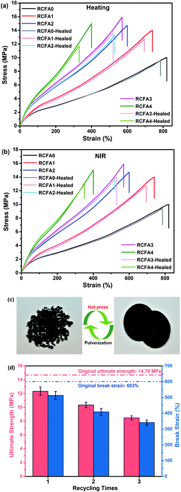
MWCNTs have been widely used as fillers to enhance the mechanical properties of nanocomposites.18,48 When the modified MWCNTs are added into the RCFA and form a uniform dispersion, the mechanical strength of RCFA can be significantly enhanced due to the high specific surface of MWCNTs and the hydrogen bonding interactions between urea-g-MWCNTs and F4PU resin.Fig. 5a shows the stress–strain curves of RCFA with different contents of modified MWCNTs, and the detailed ultimate strength and break strain are listed in Table S1 (ESI†). From the stress–strain curves, it can be seen that with the increase of MWNCT content, the mechanical strength was improved. The ultimate strength of RCFA1, RCFA2 and RCFA3 increased to 14.10, 14.79 and 15.95 MPa, respectively, while the break strain decreased. Although the content of the modified MWCNTs in RCFA4 was higher than that of other samples, its tensile strength was the lowest. This can be attributed to the stress tending to concentrate on MWCNTs at a high content, which resulted in an easy break during the stretching process and the low tensile strength.49 Moreover, the effects of the different kinds of modified MWCNTs on the mechanical properties were investigated, as shown in Fig. 5b. Compared with RCFA0 with pristine MWCNTs, RCFA0 with urea-g-MWCNTs had a higher ultimate strength and break strain due to the large amount of hydrogen bonds formed between F4PU resin and urea-g-MWCNTs. However, the mechanical properties of RCFA0 with Ag@MWCNTs was not as good as those of RCFA0 with pristine MWCNTs and urea-g-MWCNTs. This may be due to the fact that Ag nanoparticles on the surface of MWCNTs prevented MWCNTs from contacting with the polymer matrix, resulting in poor combination between Ag@MWCNTs and F4PU resin, which weakened the strength of RCFA.50 Therefore, we will continue to study it. Therefore, we used a mixture of the two kinds of modified MWCNTs to prepare the RCFA so as to achieve both good mechanical properties and high electric conductivity.
3.4 Self-healing and reprocessable abilities of RCFA
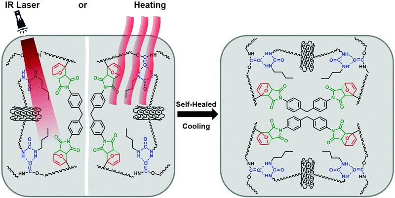
According to the nature of DA chemistry,51 the self-healing and reprocessable mechanism of RCFA has been studied based on a temperature-dependent reversible covalent network. Due the reversible cross-linked network, the RCFA can relax stress at high temperature. Fig. 5c shows the stress relaxation curves of RCFA with different contents of modified MWCNTs at 140 °C. From Fig. 5c, we can see that all samples exhibited complete stress relaxation at 140 °C within 40 min. Besides, the solvent exposure test was used to investigate the reversible network of RCFA. As shown in Fig. 5d, the solvent remained colorless after immersing RCFA samples into DMF for 5 days. However, after heating DMF to 140 °C for 2 h, all RCFA samples were dissolved and the color of the solvent changed from colorless to dark yellow. These phenomena can be explained by the fact that the network of the RFCA began to undergo slow decomposition over 140 °C, which proved that the RCFA had self-healing and reprocessable abilities under thermal stimulation.For the self-healing test, all RCFA samples were shaped into 10 mm width and 2 mm thickness, and then the samples were into two pieces with a blade. The self-healing process was conducted by putting two pieces together under heating or NIR irradiation, as shown in Fig. 6. Carbon nanotubes can generate significant amounts of heat under NIR irradiation. The polymer matrix performed the rDA reaction and rupture of hydrogen bonds under thermal stimulation. Subsequently, the addition reaction of disconnected furan rings and maleimide groups as well as the re-establishment of hydrogen bonds occurred between the fractured surfaces during cooling down to room temperature. Fig. 7a and b show the stress–strain curves of the RCFA healed by heating at 140 °C for 30 min and under NIR irradiation for 20 min, respectively. The RCFA sample exhibited fast self-healing ability compared with other self-healing materials (Table S2, ESI†). The detailed information of the mechanical properties and self-healing efficiency of RCFA samples is listed in Table S3 (ESI†). Moreover, the self-healing efficiency gradually decreased with increasing modified MWCNT content. This is because the MWCNTs may reduce the mobility of polymer chains and prevent the DA reaction.52 In particular, when the filler content was 20%, the self-healing efficiency of the RCFA sample self-healed by NIR radiation was significantly higher than that self-healed by heating. This may be attributed to the improved photothermal conversion efficiency of the RCFA caused by the high content of MWCNTs.
A reprocessing experiment was performed by cutting the representative RCFA2 sample into microparticles and then putting them into the mould under 5 MPa at 150 °C for 2 h. As shown in Fig. 7c, the reprocessable RCFA2 can be reshaped into a circle. Besides, it showed excellent mechanical properties after reprocessing (Fig. 7d). The ultimate strength/break strain of the first, second, and third reprocessable RCFA2 samples was 12.33 MPa/513%, 10.34 MPa/409%, and 8.47 MPa/341%, respectively, which were compared with the 14.79 MPa/603% value of the original RCFA2 sample. The fast self-healing and repeated reprocessable properties of RCFA may be helpful to improve its service life and recyclability.
3.5 Electrical conductivity under mechanical deformation of RCFA
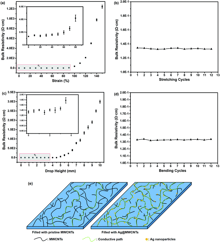
Flexible electronic technology enables devices to wrap around complex shapes or roll up for saving space. Thus, flexible electronics impose strict demands for interconnection.53,54 In addition to the robust mechanical properties and adequate flexibility, high electrical conductivity under mechanical deformation is essential.Considering the above requirements, we take RCFA2 as a typical example to investigate its electrical conductivity in the static state and under mechanical deformation, because it has excellent mechanical properties and flexibility as well as superior self-healing efficiency. Fig. 8a shows the electrical resistivity change of the RCFA2 sample under stretching deformation (Fig. S4, ESI†). The electrical resistivity of the RCFA2 sample was about 0.134 Ω cm in the static state. When the strain of RCFA2 increased from 10% to 40%, the electrical resistivity was 0.151, 0.142, 0.152 and 0.159 Ω cm, respectively. The changes of the electrical resistivity were less than 20%. In particular, the electrical conductivity was constant even after 12 cycles of stretching, as shown in Fig. 8b. The effect of bending deformation on the electrical conductivity of the RCFA2 sample was also investigated. The measurement was conducted with a three point fixture and the bending degree was determined by the drop height (Fig. S5, ESI†). As shown in Fig. 8c, there were no significant changes in the resistance when the drop height was less than 3 mm and the electrical resistivity was constant after 12 cycles of bending as well (Fig. 8d). Compared with RCFA2 filled with Ag@MWCNTs and urea-g-MWCNTs, the RCFA having the same content of pristine MWCNTs and urea-g-MWCNTs exhibited a lower electrical conductivity, and it did not remain unchanged under mechanical deformation. As shown in Fig. S6 and S7 (ESI†), the electrical conductivity of the RCFA sample filled with pristine MWCNTs and urea-g-MWCNTs was 0.833 Ω cm in the static state, while it increased to 3.15 Ω cm under 10% strain and 5.94 Ω cm under 1 mm drop height, respectively. In order to explain the above phenomena, a model was proposed, as shown in Fig. 8e. The electric resistance of RCFA is related to two factors: one is the intrinsic electric resistance of MWCNTs, and the other is the high contact electric resistance between MWCNTs.55 Comparing with the pristine MWCNTs, Ag nanoparticles decorated on the surface of MWCNTs not only act as a nanospacer to increase the interlayer spacing for a higher contact probability between MWCNTs, but also act as a conductor to improve the electrical conductivity between MWCNTs. As a result, these Ag nanoparticles form continuous contact areas so as to provide more conductive paths between MWCNTs.
3.6 Applications of RCFA in flexible electronics
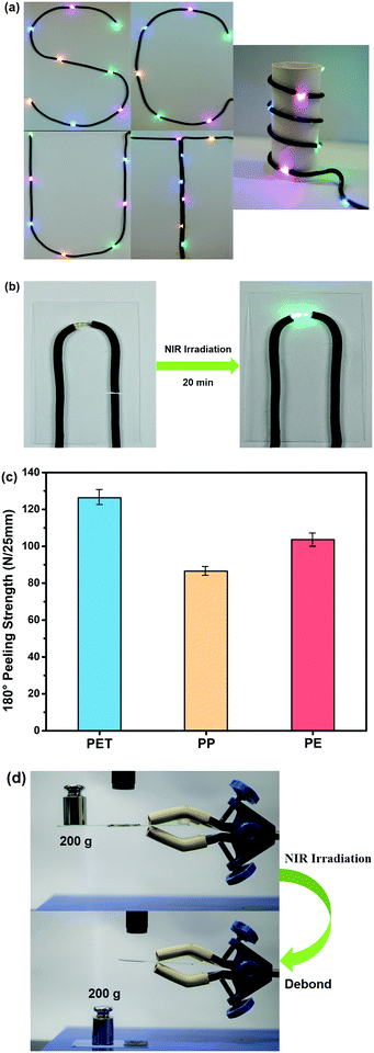
The prepared RCFA in this study can meet the requirements of flexible electronics, including robust mechanical strength, excellent flexibility, low curing temperature, fast self-healing and high electrical conductivity. Herein, we explore the applications of RCFA in flexible electronics.We take RCFA2 as an example to study the following applications. Fig. 9a shows RCFA2 used as an interconnect material of light-emitting-diode (LED) arrays. The cured RCFA2 was shaped into different patterns on a flat substrate or a cylindrical substrate. The bending deformation had no effect on the brightness of the LED arrays, indicating the excellent power transmission of RCFA2. The self-healing property of RCFA2 used as an interconnect material is shown in Fig. 9b. RCFA2 was cut with a blade, and then the fractured RCFA2 was joined together under NIR irradiation for 20 min. The self-healed RCFA2 still has good electrical conductivity, and the LED can work normally.
It is necessary for RCFA to have good adhesion on various substrates. Thus, the 180° peeling strength of RCFA2 on flexible PET, PP and PE films was tested, as shown in Fig. 9c. The 180° peeling strength of RCFA2 on PET, PP and PE was 126.3, 86.4 and 103.7 N/25 mm, respectively, indicating the excellent adhesion ability of RCFA2 to different substrates. However, good bonding between substrates usually results in difficult disassembly for recycling in flexible electronics. As shown in Fig. 9d, two glass substrates were bonded by RCFA2 and the bonding strength was strong enough to withstand a 200 g weight. However, after being irradiated by NIR laser for 35 min, the adhesive joint was debonded due to the dissociation of the cross-linked network of RCFA2. Consequently, the disappeared cohesive strength of the joint led to a successful disassembly of the glass substrates. This result is consistent with the measurement of the stress relaxation.
RCFA2 can also be used as radio frequency identification (RFID) tag antenna. RFID tag is a small device that can be attached to an object for identification by radio frequency waves from a distance, which is widely used for payment at a highway toll station, supply chain management, rapid checkout of products, and so on.56,57 The RFID antenna designed in this paper was based on the half wavelength in length, as shown in Fig. S8 (ESI†). An Alien H3 RFID chip was selected as it can provide reflective signals for reading even at a low power. We printed RFID tags onto the surface of PP paper, and PE and PET films to investigate the practicability of RFID tags on different flexible substrates (Fig. 10a). The read range of the RFID tags on the different substrates is shown in Fig. 10b. The maximum read rage is more than 6.5 meters, which was similar to the RFID tags used in industry.
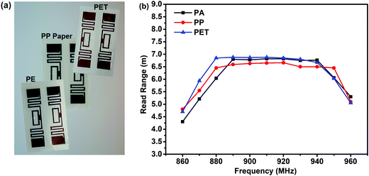 | ||
| Fig. 10 (a) Optical images of RFID tags printed on various flexible substrates. (b) Read range of RFID tags prepared on different substrates. | ||
4. Conclusions
In summary, we reported a facile way to prepare a reversible conductive flexible adhesive based on Diels–Alder chemistry combining F4PU resin, urea-g-MWCNTs and Ag@MWCNTs. The F4PU resin can not only form hydrogen bonding interactions with urea-g-MWCNTs, but also react with bismaleimide at a low temperature and form reversible DA bonds. The two kinds of functional MWCNTs endowed RCFA with a robust mechanical property and high electrical conductivity, as well as enabling it to act as a photothermal conversion switch by converting NIR irradiation to thermal energy so as to realize the fast self-healing of RCFA and debonding of adhesive joints. With the incorporation of 3 wt% urea-g-MWCNTs and 7 wt% Ag@MWCNTs, the ultimate strength of RCFA increased from 10.09 MPa to 14.79 MPa, the break strain reached as high as 603%, and the self-healing efficiency increased up to 92.16% under NIR irradiation for 20 min. Moreover, the RCFA exhibited high electrical conductivity due to the decoration of Ag nanoparticles on MWCNTs. The electrical resistivity of RCFA was about 0.15 Ω cm in the static state and showed little change under stretching or bending deformation. It proved to be an effective conductor for various shapes of LED arrays and antennas of RFID tag. These results demonstrate that the RCFA will be a very promising interconnect material for flexible electronics.Conflicts of interest
There are no conflicts to declare.Acknowledgements
We appreciate the financial support from the National Natural Science Foundation of China under grant No. 21878108.References
- Z. Liu, H. Li, M. Zhu, Y. Huang, Z. Tang, Z. Pei, Z. Wang, Z. Shi, J. Liu, Y. Huang and C. Zhi, Towards Wearable Electronic Devices: A Quasi-Solid-State Aqueous Lithium-ion Battery with Outstanding Stability, Flexibility, Safety and Breathability, Nano Energy, 2018, 44, 164–173 CrossRef CAS.
- J. Jang, Displays develop a new flexibility, Mater. Today, 2006, 9, 46–52 CrossRef CAS.
- P. Xiong, L. Peng, D. Chen, Y. Zhao, X. Wang and G. Yu, Two-Dimensional Nanosheets Based Li-Ion Full Batteries with High Rate Capability and Flexibility, Nano Energy, 2015, 12, 816–823 CrossRef CAS.
- T. Cheng, Y. Zhang, W. Y. Lai and W. Huang, Stretchable Thin-Film Electrodes for Flexible Electronics with High Deformability and Stretchability, Adv. Mater., 2015, 27, 3349–3376 CrossRef CAS PubMed.
- N. Choudhary, M. Patel, Y. H. Ho, N. B. Dahotre, W. Lee, J. Y. Hwang and W. Choi, Directly Deposited MoS2 Thin Film Electrodes for High Performance Supercapacitors, J. Mater. Chem. A, 2015, 3, 24049–24054 RSC.
- T. Mitra, F. Moreau, A. Nevin, C. U. Perotto, A. Summerfield, E. S. Davies, E. A. Gibson, T. L. Easun and M. Schröder, Characterisation of Redox States of Metal-Organic Frameworks by Growth on Modified Thin-Film Electrodes, Chem. Sci., 2018, 9, 6572–6579 RSC.
- E. Fortunato, P. Barquinha and R. Martins, Oxide Semiconductor Thin-Film Transistors: A Review of Recent Advances, Adv. Mater., 2012, 24, 2945–2986 CrossRef CAS PubMed.
- Y. Zang, F. Zhang, D. Huang, X. Gao, C. Di and D. Zhu, Flexible Suspended Gate Organic Thin-Film Transistors for Ultra-Sensitive Pressure Detection, Nat. Commun., 2015, 6, 6269 CrossRef CAS PubMed.
- C. Zhang and K. S. Suslick, A Colorimetric Sensor Array for Organics in Water, J. Am. Chem. Soc., 2005, 127, 11548–11549 CrossRef CAS PubMed.
- N. T. Greene and K. D. Shimizu, Colorimetric Molecularly Imprinted Polymer Sensor Array Using Dye Displacement, J. Am. Chem. Soc., 2005, 127, 5695–5700 CrossRef CAS PubMed.
- Y. Xiang, S. Lu and S. P. Jiang, Layer-by-Layer Self-Assembly in the Development of Electrochemical Energy Conversion and Storage Devices from Fuel Cells to Supercapacitors, Chem. Soc. Rev., 2012, 41, 7291–7321 RSC.
- Y. Li, Z.-Y. Fu and B.-L. Su, Hierarchically Structured Porous Materials for Energy Conversion and Storage, Adv. Funct. Mater., 2012, 22, 4634–4667 CrossRef CAS.
- K. K. Fu, J. Cheng, T. Li and L. Hu, Flexible Batteries: From Mechanics to Devices, ACS Energy Lett., 2016, 1, 1065–1079 CrossRef CAS.
- H. Gwon, J. Hong, H. Kim, D.-H. Seo, S. Jeon and K. Kang, Recent Progress on Flexible Lithium Rechargeable Batteries, Energy Environ. Sci., 2014, 7, 538–551 RSC.
- M. Zarek, M. Layani, I. Cooperstein, E. Sachyani, D. Cohn and S. Magdassi, 3D Printing of Shape Memory Polymers for Flexible Electronic Devices, Adv. Mater., 2016, 28, 4449–4454 CrossRef CAS PubMed.
- Y. Liu, K. He, G. Chen, W. R. Leow and X. Chen, Nature-Inspired Structural Materials for Flexible Electronic Devices, Chem. Rev., 2017, 117, 12893–12941 CrossRef CAS PubMed.
- W. Wu, Inorganic Nanomaterials for Printed Electronics: A Review, Nanoscale, 2017, 9, 7342–7372 RSC.
- L. Du, P. Yang, X. Yu, P. Liu, J. Song and W. Mai, Flexible Supercapacitors Based on Carbon Nanotube/MnO2 Nanotube Hybrid Porous Films for Wearable Electronic Devices, J. Mater. Chem. A, 2014, 2, 17561–17567 RSC.
- S.-M. Lee, J.-H. Kim and J.-H. Ahn, Graphene as a Flexible Electronic Material: Mechanical Limitations by Defect Formation and Efforts to Overcome, Mater. Today, 2015, 18, 336–344 CrossRef CAS.
- T. Y. Lee, K. N. Tu, S. M. Kuo and D. R. Frear, Electromigration of Eutectic SnPb Solder Interconnects for Flip Chip Technology, J. Appl. Phys., 2001, 89, 3189–3194 CrossRef CAS.
- D. Li, C. Liu and P. P. Conway, Characteristics of Intermetallics and Micromechanical Properties during Thermal Aging of Sn-Ag-Cu Flip-Chip Solder Interconnects, Mater. Sci. Eng., A, 2005, 391, 95–103 CrossRef.
- L. R. Garcia, W. R. Osório, L. C. Peixoto and A. Garcia, Wetting Behavior and Mechanical Properties of Sn-Zn and Sn-Pb Solder Alloys, J. Electron. Mater., 2009, 38, 2405–2414 CrossRef CAS.
- S. Choi, T. R. Bieler, J. P. Lucas and K. N. Subramanian, Characterization of the Growth of Intermetallic Interfacial Layers of Sn-Ag and Sn-Pb Eutectic Solders and Their Composite Solders on Cu Substrate during Isothermal Long-Term Aging, J. Electron. Mater., 1999, 28, 1209–1215 CrossRef CAS.
- M. Inoue, H. Muta, T. Maekawa, S. Yamanaka and K. Suganuma, Temperature Dependence of Electrical and Thermal Conductivities of an Epoxy-Based Isotropic Conductive Adhesive, J. Electron. Mater., 2008, 37, 462–468 CrossRef CAS.
- U. Vietri, L. Guadagno, M. Raimondo, L. Vertuccio and K. Lafdi, Nanofilled Epoxy Adhesive for Structural Aeronautic Materials, Composites, Part B, 2014, 61, 73–83 CrossRef CAS.
- M. H. Gabr, W. Okumura, H. Ueda, W. Kuriyama, K. Uzawa and I. Kimpara, Mechanical and Thermal Properties of Carbon Fiber/Polypropylene Composite Filled with Nano-Clay, Composites, Part B, 2015, 69, 94–100 CrossRef CAS.
- C. Zhao, H. Qin, F. Gong, M. Feng, S. Zhang and M. Yang, Mechanical, Thermal and Flammability Properties of Polyethylene/Clay Nanocomposites, Polym. Degrad. Stab., 2005, 87, 183–189 CrossRef CAS.
- S. A. Jabarin and E. A. Lofgren, Thermal Stability of Polyethylene Terephthalate, Polym. Eng. Sci., 1984, 24, 1056–1063 CrossRef.
- R. K. Shah and D. R. Paul, Organoclay Degradation in Melt Processed Polyethylene Nanocomposites, Polymer, 2006, 47, 4075–4084 CrossRef CAS.
- S. O. Han, D. W. Lee and O. H. Han, Thermal Degradation of Crosslinked High Density Polyethylene, Polym. Degrad. Stab., 1999, 63, 237–243 CrossRef CAS.
- S. Ravindran, S. Chaudhary, B. Colburn, M. Ozkan and C. S. Ozkan, Covalent Coupling of Quantum Dots to Multiwalled Carbon Nanotubes for Electronic Device Applications, Nano Lett., 2003, 3, 447–453 CrossRef CAS.
- C. Li, Q. Li, L. Cheng, T. Li, H. Lu, L. Tang, K. Zhang, E. Songfeng, J. Zhang, Z. Li and Y. Yao, Conductivity Enhancement of Polymer Composites Using High-Temperature Short-Time Treated Silver Fillers, Composites, Part A, 2017, 100, 67–70 Search PubMed.
- W. Shen, L. Feng, X. Liu, H. Luo, Z. Liu, P. Tong and W. Zhang, Multiwall Carbon Nanotubes-Reinforced Epoxy Hybrid Coatings with High Electrical Conductivity and Corrosion Resistance Prepared via Electrostatic Spraying, Prog. Org. Coat., 2016, 90, 139–146 CrossRef CAS.
- R. Ma, S. Kwon, Q. Zheng, H. Y. Kwon, J. I. Kim, H. R. Choi and S. Baik, Carbon-Nanotube/Sliver Networks in Nitrile Butadiene Rubber for Highly Conductive Flexible Adhesives, Adv. Mater., 2012, 24, 3344–3349 CrossRef CAS PubMed.
- C. Li, X. Gong, L. Tang, K. Zhang, J. Luo, L. Ling, J. Pu, T. Li, M. Li and Y. Yao, Electrical Property Enhancement of Electrically Conductive Adhesives through Ag-Coated-Cu Surface Treatment by Terephthalaldehyde and Iodine, J. Mater. Chem. C, 2015, 3, 6178–6184 RSC.
- C. Li, Q. Li, X. Long, T. Li, J. Zhao, K. Zhang, E. Songfeng, J. Zhang, Z. Li and Y. Yao, In Suit Generation of Photosensitive Silver Halide for Improving the Conductivity of Electrically Conductive Adhesives, ACS Appl. Mater. Interfaces, 2017, 9, 29047–29054 CrossRef CAS PubMed.
- M. J. Yim, Y. Li, K. Moon, K. W. Paik and C. P. Wong, Review of Recent Advances in Electrically Conductive Adhesive Materials and Technologies in Electronic Packaging, J. Adhes. Sci. Technol., 2008, 22, 1593–1630 CrossRef CAS.
- T. V. Nguyen, P. N. Tri, T. D. Nguyen, R. E. I. Aidani, V. T. Trinh and C. Decker, Accelerated Degradation of Water Borne Acrylic Nanocomposites Used in Outdoor Protective Coatings, Polym. Degrad. Stab., 2016, 128, 65–76 CrossRef CAS.
- C. Fang, Y. Jing and Z. Lin, The Application Research of Environment-Friendly Reactive Surfactants in the Acrylate Emulsion Pressure Sensitive Adhesives, Int. J. Adhes. Adhes., 2017, 73, 1–7 CrossRef CAS.
- T. G. Dastidar and A. N. Netravali, A Soy Flour Based Thermoset Resin without the Use of Any External Crosslinker, Green Chem., 2013, 15, 3243–3251 RSC.
- V. K. Rangari, G. M. Mohammad, S. Jeelani, A. Hundley, K. Vig, S. R. Singh and S. Pillai, Synthesis of Ag/CNT Hybrid Nanoparticles and Fabrication of Their Nylon-6 Polymer Nanocomposite Fibers for Antimicrobial Applications, Nanotechnology, 2010, 21, 095102 CrossRef PubMed.
- Z. Spitalsky, D. Tasis, K. Papagelis and C. Galiotis, Carbon Nanotube-Polymer Composites: Chemistry, Processing, Mechanical and Electrical Properties, Prog. Polym. Sci., 2010, 35, 357–401 CrossRef CAS.
- Y. Ma, C. Yan, H. Xu, D. Liu, P. Shi, Y. Zhu and J. Liu, Enhanced Interfacial Properties of Carbon Fiber Reinforced Polyamide 6 Composites by Grafting Graphene Oxide onto Fiber Surface, Appl. Surf. Sci., 2018, 452, 286–298 CrossRef CAS.
- L. Ma, H. L. Zhuang, S. Wei, K. E. Hendrickson, M. S. Kim, G. Cohn, R. G. Hennig and L. A. Archer, Enhanced Li-S Batteries Using Amine-Functionalized Carbon Nanotubes in the Cathode, ACS Nano, 2016, 10, 1050–1059 CrossRef CAS PubMed.
- J. Li, G. Zhang, L. Deng, S. Zhao, Y. Gao, K. Jiang, R. Sun and C. Wong, In Situ Polymerization and Mechanical Reinforced, Thermal Healable Graphene Oxide/Polyurethane Composites Based on Diels-Alder Chemistry, J. Mater. Chem. A, 2014, 2, 20642–20649 RSC.
- G. Fu, L. Yuan, G. Liang and A. Gu, Heat-Resistance Polyurethane Film with Great Electrostatic Dissipation Capacity and Very High Thermally Reversible Self-Healing Efficiency Based on Multi-Furan and Liquid Multi-Maleimide Polymers, J. Mater. Chem. A, 2016, 4, 4232–4241 RSC.
- S. Mallakpour and L. Khodadadzadeh, Fructose Functionalized MWCNT as A Filler for Starch Nanocomposites: Fabrication and Characterizations, Prog. Org. Coat., 2018, 114, 244–249 CrossRef CAS.
- Y. Xu, Z. Liu, X. Zhang, Y. Wang, J. Tian, Y. Huang, Y. Ma, X. Zhang and Y. Chen, A Graphene Hybrid Material Covalently Functionalized with Porphyrin: Synthesis and Optical Limiting Property, Adv. Mater., 2009, 21, 1275–1279 CrossRef CAS.
- J. T. Kim, B. K. Kim, E. Y. Kim, S. H. Kwon and H. M. Jeong, Synthesis and Properties of Near IR Induced Self-Healable Polyurethane/Graphene Nanocomposites, Eur. Polym. J., 2013, 49, 3889–3896 CrossRef CAS.
- W. Zhang, W. Li, J. Wang, C. Qin and L. Dai, Composites of Polyvinyl Alcohol and Carbon Nanotubes Decorated with Silver Nanoparticles, Fibers Polym., 2010, 11, 1132–1136 CrossRef CAS.
- Y.-L. Liu and T.-W. Chuo, Self-Healing Polymers Based on Thermally Reversible Diels-Alder Chemistry, Polym. Chem., 2013, 4, 2194–2205 RSC.
- L. D. Perez, M. A. Zuluaga, T. Kyu, J. E. Mark and B. L. Lopez, Preparation, Characterization, and Physical Properties of Multiwall Carbon Nanotube/Elastomer Composites, Polym. Eng. Sci., 2009, 49, 866–874 CrossRef CAS.
- C. Yang, W. Lin, Z. Li, R. Zhang, H. Wen, B. Gao, G. Chen, P. Gao, M. M. F. Yuen and C. P. Wong, Water-Based Isotropically Conductive Adhesive: Towards Green and Low-Cost Flexible Electronics, Adv. Funct. Mater., 2011, 21, 4582–4588 CrossRef CAS.
- T. Wu and B. Chen, Synthesis of Multiwalled Carbon Nanotube-Reinforced Polyborosiloxane Nanocomposites with Mechanically Adaptive and Self-Healing Capabilities for Flexible Conductors, ACS Appl. Mater. Interfaces, 2016, 8, 24071–24078 CrossRef CAS PubMed.
- S.-H. Lee, C.-C. Teng, C.-C. M. Ma and I. Wang, Highly Transparent and Conductive Thin Films Fabricated with Nnao-Sliver/Double-Walled Carbon Nanotube Composites, J. Colloid Interface Sci., 2011, 364, 1–9 CrossRef CAS PubMed.
- P. Kumar, H. W. Reinitz, J. Simunovic, K. P. Sandeep and P. D. Franzon, Overview of RFID Technology and Its Applications in the Food Industry, Food Sci., 2009, 74, 101–106 CrossRef PubMed.
- W. Clemens, W. Fix, J. Ficker, A. Knobloch and A. Ullmann, From Polymer Transistors Toward Printed Electronics, J. Mater. Res., 2004, 19, 1963–1973 CrossRef CAS.
Footnote |
| † Electronic supplementary information (ESI) available. See DOI: 10.1039/c9tc06765e |
| This journal is © The Royal Society of Chemistry 2020 |


