4 V class aqueous hybrid electrochemical capacitor with battery-like capacity†
Sho
Makino
a,
Yuto
Shinohara
a,
Takayuki
Ban
a,
Wataru
Shimizu
a,
Keita
Takahashi
b,
Nobuyuki
Imanishi
b and
Wataru
Sugimoto
*a
aMaterials and Chemical Engineering, Faculty of Textile Science and Technology, Shinshu University, 3-15-1 Tokida, Ueda, 386-8567, Nagano, Japan. E-mail: wsugi@shinshu-u.ac.jp; Fax: +81-268-21-5452; Tel: +81-268-21-5455
bDepartment of Chemistry, Faculty of Engineering, Mie University, 1577 Kurimamachiya-cho, Tsu, 514-8507, Mie, Japan. E-mail: imanishi@chem.mie-u.ac.jp; Fax: +81-59-231-9478; Tel: +81-59-231-9420
First published on 16th October 2012
Abstract
A new aqueous hybrid electrochemical capacitor consisting of a porous positive capacitive electrode and a water-stable multi-layered Li negative electrode is demonstrated. The new cell design affords cell voltages close to 4 V in a mild aqueous electrolyte. Application of a pseudocapacitive positive electrode with high specific charge results in specific energy comparable to present rechargeable batteries.
Electrochemical capacitors are energy storage devices capable of storing/delivering electrical energy at rates faster than batteries, thereby finding applications in load leveling for efficient energy usage.1 However, as the charge storage is based on reversible ion adsorption in porous electrode materials, the amount of charge that can be stored is typically limited to an order smaller than batteries. Here we report a new hybrid electrochemical capacitor that can be operated using a mild aqueous electrolyte providing cell voltages as high as 4.3 V with a specific energy of 114 Wh kg−1 using a MnO2 positive electrode, or 3.8 V with 544 Wh kg−1 based on a RuO2 nanosheet positive electrode, potentially exceeding conventional electrochemical capacitors, hybrid electrochemical capacitors and even rechargeable batteries. The key design of the device is the appropriate choice of a pseudo-capacitive material that provides high specific capacitance and high positive potential in aqueous electrolytes and a water stable multi-layered Li electrode in an asymmetric configuration. The aqueous hybrid electrochemical capacitor proposed here not only closes the gap between electrochemical capacitors and batteries, but the new design principle opens the possibility of the use of pseudo-capacitive material for post-lithium ion battery technology.
Electrochemical double layer capacitors (EDLC) based on a symmetric configuration of two porous carbon electrodes can deliver specific energies of up to ∼6 Wh kg−1.2 The specific energy can be increased by using two different types of electrode materials in an asymmetric configuration with one electrode behaving like an electrochemical capacitor and the other performing like a battery.3 A typical hybrid electrochemical capacitor (hybrid EC) is the lithium ion capacitor (LIC), which uses an activated carbon positive electrode and a Li-doped carbon negative electrode.4–7 The charge/discharge curves of a LIC resemble those of an EDLC, and the energy and power performance of the cell is governed by the capacitive positive electrode. The cell voltage (∼3.8 V) is determined by the decomposition of the electrolyte, typically a lithium salt dissolved in a non-aqueous electrolyte. The low standard electrode potential of E° = −3.045 V vs. SHE for Li+ + e− → Li results in a cell voltage larger than those for EDLCs. These characteristics lead to an energy density of ∼15 Wh kg−1, which is comparable to lead-acid batteries but still cannot compete with lithium ion batteries (LiBs). Thus, researchers have focused on increasing the specific capacitance of the positive electrode and developing new electrolytes. Metal oxide electrodes can provide specific capacitance higher than activated carbon owing to the contribution from highly reversible surface redox processes (pseudo-capacitance).2,8–12 A typical example is ruthenium based oxides, which afford a capacitance of ∼700 F g−1, 3 to 7 times higher than activated carbon (100–200 F g−1).13–17 Unfortunately, such high specific capacitance can only be achieved in aqueous electrolytes, limiting the cell voltage to ∼1.2 V. Hybrid EC designs can circumvent the limitation of aqueous electrolytes by extending the operating voltage window beyond the thermodynamic water electrolysis voltage, giving an attractive 2 V device in some cases.3,18 The technology behind 2 V aqueous hybrid ECs is the use of a positive electrode with high oxygen evolution over-potential such as manganese oxide, giving a specific energy of 19 Wh kg−1.18
In order to take advantage of the high specific capacitance of pseudo-capacitive oxides that can only be realized in aqueous electrolytes and at the same time utilize the low electrode potential of lithium that can only be operated in non-aqueous environments, we have exploited the use of a water stable multi-layered Li electrode,19,20 initially developed as the anode for an aqueous rechargeable Li-air battery. This new advanced hybrid EC can be operated using a mild aqueous electrolyte providing specific energy exceeding that of LICs and potentially comparable to LiBs. Cell voltages as high as 4.3 V can be realized when MnO2 is used as the positive electrode.
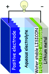
The multi-layered Li electrode consists of lithium metal, a LISICON-type solid glass ceramic (Li1+x+y(Ti,Ge)2−xAlxSiyP3−yO12 (x ∼ 0.25, y ∼ 0.3); Ohara Inc., Japan, hereafter denoted as LTAP) as the water-stable solid electrolyte, and a buffer layer consisting of polyethylene oxide with Li(CF3SO2)2N polymer electrolyte (PEO-LiTFSI) between the lithium metal and the solid electrolyte. These 3 layers were sealed leaving a 5 mm × 5 mm window cut out for the solid electrolyte (LTAP) to come into contact with the aqueous electrolyte. Fig. 1 illustrates the cell configuration of the advanced hybrid EC.
 | ||
| Fig. 1 Schematic representation of the aqueous hybrid EC using multi-layered Li electrode. | ||
Four materials were used as the positive electrode. Activated carbon (AC; 2![[thin space (1/6-em)]](https://www.rsc.org/images/entities/char_2009.gif) 000 m2 g−1, MSP-20, Kansai Coke and Chemicals, Japan) was used as received. MnO2, RuO2·0.5H2O and RuO2 nanosheets were prepared according to literature.18,21,17,22 The positive electrodes were prepared by depositing a controlled amount of the active material dispersed in ultra-pure H2O onto a mirror-polished glassy carbon electrode (5 mm in diameter). The amount deposited was 0.204 mg cm−2 for AC and MnO2 + acetylene black (7
000 m2 g−1, MSP-20, Kansai Coke and Chemicals, Japan) was used as received. MnO2, RuO2·0.5H2O and RuO2 nanosheets were prepared according to literature.18,21,17,22 The positive electrodes were prepared by depositing a controlled amount of the active material dispersed in ultra-pure H2O onto a mirror-polished glassy carbon electrode (5 mm in diameter). The amount deposited was 0.204 mg cm−2 for AC and MnO2 + acetylene black (7![[thin space (1/6-em)]](https://www.rsc.org/images/entities/char_2009.gif) :
:![[thin space (1/6-em)]](https://www.rsc.org/images/entities/char_2009.gif) 3 in mass), and RuO2·0.5 H2O. In the case of RuO2 nanosheets the deposited mass was 0.0204 mg cm−2. In order to evaluate the electrochemical capacitor properties of the positive electrodes, cyclic voltammetry was conducted in 1.0 M LiCl or Li2SO4 (60 °C) using a three electrode cell comprised of a Ag/AgCl reference electrode and a platinum counter electrode. Electrode potentials will be referred to the reversible hydrogen electrode (RHE) potential scale. A Luggin capillary faced the working electrode at a distance of 2 mm. Cyclic voltammetry was conducted between 0.2 and 1.2 V vs. RHE at scan rates of 500 to 5 mV s−1. The specific capacitance was calculated by averaging the anodic and cathodic charge from the cyclic voltammogram.
3 in mass), and RuO2·0.5 H2O. In the case of RuO2 nanosheets the deposited mass was 0.0204 mg cm−2. In order to evaluate the electrochemical capacitor properties of the positive electrodes, cyclic voltammetry was conducted in 1.0 M LiCl or Li2SO4 (60 °C) using a three electrode cell comprised of a Ag/AgCl reference electrode and a platinum counter electrode. Electrode potentials will be referred to the reversible hydrogen electrode (RHE) potential scale. A Luggin capillary faced the working electrode at a distance of 2 mm. Cyclic voltammetry was conducted between 0.2 and 1.2 V vs. RHE at scan rates of 500 to 5 mV s−1. The specific capacitance was calculated by averaging the anodic and cathodic charge from the cyclic voltammogram.
Test cells were constructed by immersing the multi-layered Li electrode and positive electrode in an aqueous electrolyte and can be expressed as Li | PEO-LiTFSI | LTAP | 1.0 M LiCl or Li2SO4 aq. | positive electrode. Charge/discharge cycle tests were obtained with beaker-type flooded cells at 60 °C in a two electrode configuration. The specific charge was determined from the discharge curves based on the mass of the positive electrode unless otherwise noted. The specific capacitance in the two-electrode system was calculated using the following equation,
| C = I × dt/dV |
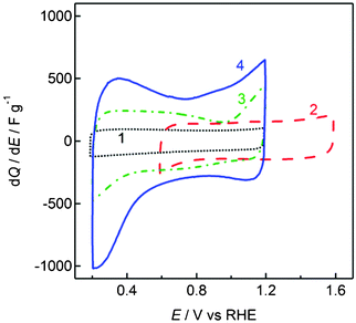
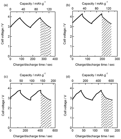
As a proof-of-concept to demonstrate the principle operation of the advanced hybrid EC, activated carbon (AC) was first chosen as the positive electrode. A neutral aqueous electrolyte (1 M LiCl) was used in this study to avoid unsolicited degradation of the solid electrolyte and the temperature of the cell was set at 60 °C to ensure good conductivity of the multi-layered Li negative electrode.19 First, the EDLC behavior of the AC electrode was characterized in a three-electrode configuration. The cyclic voltammogram of the AC electrode exhibits a rectangular form, typical of non-Faradaic electric double layer formation at the electrode–electrolyte interface (Fig. 2). The specific capacitance was 100 F g−1 at a scan rate of 5 mV s−1. Steady-state charge/discharge curves of the hybrid EC (Li | PEO-LiTFSI | LTAP | 1.0 M LiCl aq. | AC) cycled between 2.9 and 3.9 V at a constant current density of 0.255 mA cm−2 are shown in Fig. 3(a). The voltage increases/decreases linearly with time, typical of capacitive charge storage/release. The specific charge and capacitance calculated based on the AC electrode from the discharge curve were 32.7 mAh g−1 and 124 F g−1, respectively, in agreement with the capacitance obtained for the AC electrode in a three-electrode configuration. The specific energy is 108 Wh kg−1. Consecutive cycling tests conducted at 0.255 mA cm−2 showed good capacitance retention with only 5 and 27% loss in specific capacity after 200 and 2![[thin space (1/6-em)]](https://www.rsc.org/images/entities/char_2009.gif) 000 cycles, respectively. The loss in performance is dominated by the degradation of the multi-layered Li negative electrode.
000 cycles, respectively. The loss in performance is dominated by the degradation of the multi-layered Li negative electrode.
 | ||
| Fig. 2 Cyclic voltammograms of the positive electrodes in mild aqueous electrolytes at 50 mV s−1. 1: Activated carbon in 1.0 M LiCl; 2: MnO2, 3: RuO2·0.5H2O, 4: RuO2 nanosheets in 1.0 M Li2SO4. | ||
 | ||
| Fig. 3 (a) Steady-state charge/discharge curves of the aqueous hybrid electrochemical capacitor with activated carbon positive electrode and multi-layered Li negative electrode in mild aqueous electrolyte (Li | PEO-LiTFSI | LTAP | 1.0 M LiCl (60 °C) | AC) at 0.255 mA cm−2. Steady-state charge/discharge curves of the aqueous hybrid electrochemical capacitor with (b) MnO2, (c) RuO2·0.5H2O, (d) RuO2 nanosheets as positive electrode materials and multi-layered Li negative electrode in mild aqueous electrolyte (Li | PEO-LiTFSI | LTAP | 1.0 M Li2SO4 (60 °C) | positive electrode) at 0.255 mA cm−2 | ||
By selecting a positive electrode material with a higher over-potential for oxygen evolution, the cell voltage can be increased. As shown in the cyclic voltammogram of MnO2 in 1 M Li2SO4 (Fig. 2), the operating window is shifted to positive potentials, i.e. 0.6–1.6 V vs. RHE. Charge/discharge curves of the hybrid EC (Li | PEO-LiTFSI | LTAP | 1.0 M Li2SO4 aq. | MnO2) show capacitive behavior between 3.3–4.3 V (Fig. 3(b)). The specific charge calculated from the discharge curve at 0.255 mA cm−2 was 31.4 mAh g−1 based on MnO2, which translates to specific energy of 114 Wh kg−1. The 4.3 V cell voltage is higher than any other EC device, such as EDLCs operating in non-aqueous electrolytes (2.5 V), with ionic liquids (3.5 V), or for LICs (3.8 V).
Another advantage of the advanced hybrid EC is that the use of aqueous electrolytes allows one to fully acknowledge the performance of high capacitance pseudocapacitive materials, for example nanostructured RuO2. As a typical example, hydrous ruthenium oxide (RuO2·0.5H2O) was chosen as the positive electrode. The single electrode capacitance of RuO2·0.5H2O in 1 M Li2SO4 was 290 F g−1 at 5 mV s−1 (Fig. 2), which is lower than the specific capacitance in sulfuric acid but still a few times higher than AC. Thus, a hybrid EC with RuO2·0.5H2O (Li | PEO-LiTFSI | LTAP | 1.0 M Li2SO4 aq. | RuO2·0.5H2O) affords specific capacity of 48.2 mAh g−1 and specific energy of 149 Wh kg−1 at 0.255 mA cm−2 (Fig. 3(c)). By using a slightly more exotic material, i.e. RuO2 nanosheets derived from chemical exfoliation of layered Na0.2RuO2·0.5H2O,22 the capacitance could be enhanced to 543 F g−1 at 5 mV s−1 (Fig. 2). A cell voltage of 3.8 V with specific charge and specific energy of 177 mAh g−1 and 544 Wh kg−1, respectively, could be realized in a two-electrode configuration (Li | PEO-LiTFSI | LTAP | 1.0 M Li2SO4 aq.| RuO2ns) at 0.255 mA cm−2 (Fig. 3(d)).
For a positive electrode with 177 mAh g−1, 45.8 mg of Li is oxidized/reduced during charge/discharge. Thus hypothetically, the specific charge and specific energy including both electrodes would be 169 mAh g−1 and 520 Wh kg−1, respectively. If it is estimated that the mass of the electrodes would constitute 20% of a packaged cell, then the anticipated maximum energy density of this cell would be 104 Wh kg−1. The projected energy density is an order higher than state-of-the-art LICs and is in the higher range of rechargeable batteries. Naturally, the use of an expensive, precious material such as ruthenium oxide will be unrealistic for large-scale commercial application. It is noted that thicker RuO2ns electrodes should afford the same maximum energy density. Nonetheless, the numbers obtained in this study should represent the reachable potential of a 4 V aqueous hybrid EC.
In summary, a new aqueous electrochemical capacitor in an asymmetric configuration with high voltage and energy has been demonstrated. A number of advantages of this novel charge storage technology compared to present systems based on capacitive charge storage can be designated. First, the potential window can exceed those of aqueous MnO2/carbon hybrid ECs, carbon/carbon EDLCs and even LICs by choosing a positive electrode material with high over-potential for the oxygen evolution reaction. Second, the aqueous electrolytes are not only environmentally benign, but also allow the use of a pseudo-capacitive positive electrode with high capacitance such as nanostructured ruthenium oxide. The work is still in its preliminary stage and much research is needed before the present aqueous hybrid ECs can be realized as a potential charge storage device capable of replacing LiBs. The multi-layered Li negative electrode used is far from optimized for capacitor application; a massive and impractical amount of lithium is used in the present study due to handling reasons. There is a large family of anode material that could be possibly used, for example the use of Li-doped carbon used in LICs should decrease the overall cell size and weight. Also, development of solid electrolytes capable of use in acidic environments would allow positive electrodes with even higher capacitance. Nonetheless, the proof-of-concept of the advanced hybrid EC using a combination of aqueous capacitor positive electrode in combination with non-aqueous battery negative electrode not only closes the gap between electrochemical capacitors and batteries, but opens the possibility of the use of pseudo-capacitive materials for post-lithium ion battery technology.
Acknowledgements
We gratefully acknowledge support for this work under the Advanced Low Carbon Technology Research and Development Program (ALCA) of the Japan Science and Technology Agency (JST).References
- B. Conway, Electrochemical supercapacitors: scientific fundamentals and technological applications, Kluwer Academic/Plenum Publishers, New York, USA, 1999 Search PubMed.
- P. Simon and Y. Gogotsi, Nat. Mater., 2008, 7, 845–854 CrossRef CAS.
- J. W. Long, D. Bélanger, T. Brousse, W. Sugimoto, M. B. Sassin and O. Crosnier, MRS Bull., 2011, 36, 513–522 Search PubMed.
- G. G. Amatucci, F. Badway, A. Du Pasquier and T. Zheng, J. Electrochem. Soc., 2001, 148, A930–A939 CrossRef.
- A. Yoshino, T. Tsubata, M. Shimoyamada, H. Satake, Y. Okano, S. Mori and S. Yata, J. Electrochem. Soc., 2004, 151, A2180–A2182 CrossRef CAS.
- T. Aida, K. Yamada and M. Morita, Electrochem. Solid-State Lett., 2006, 9, A534–A536 CrossRef CAS.
- S. R. Sivakkumar and A. G. Pandolfo, Electrochim. Acta, 2012, 65, 280–287 CrossRef CAS.
- A. S. Aricò, P. Bruce, B. Scrosati, J. Tarascon and W. van Schalkwijk, Nat. Mater., 2005, 4, 366–377 CrossRef CAS.
- T. Brezesinski, J. Wang, S. H. Tolbert and B. Dunn, Nat. Mater., 2010, 9, 146–151 CrossRef CAS.
- X. Lang, A. Hirata, T. Fujita and M. Chen, Nat. Nanotechnol., 2011, 6, 232–236 CrossRef CAS.
- K. Naoi and P. Simon, Interface, 2008, 17, 34–37 Search PubMed.
- G. Wang, L. Zhang and J. Zhang, Chem. Soc. Rev., 2012, 41, 797–828 RSC.
- D. A. McKeown, P. L. Hagans, L. P. L. Carette, A. E. Russell, K. E. Swider and D. R. Rolison, J. Phys. Chem. B, 1999, 103, 4825–4832 CrossRef CAS.
- W. Sugimoto, H. Iwata, Y. Yasunaga, Y. Murakami and Y. Takasu, Angew. Chem., Int. Ed., 2003, 42, 4092–4096 CrossRef CAS.
- W. Sugimoto, H. Iwata, K. Yokoshima, Y. Murakami and Y. Takasu, J. Phys. Chem. B, 2005, 109, 7330–7338 CrossRef CAS.
- W. Sugimoto, K. Yokoshima, Y. Murakami and Y. Takasu, Electrochim. Acta, 2006, 52, 1742–1748 CrossRef CAS.
- J. P. Zheng, P. J. Cygan and T. R. Jow, J. Electrochem. Soc., 1995, 142, 2699–2703 CAS.
- T. Brousse, M. Toupin and D. Bélanger, J. Electrochem. Soc., 2004, 151, A614–A622 CrossRef CAS.
- T. Zhang, N. Imanishi, Y. Shimonishi, A. Hirano, J. Xie, Y. Takeda, O. Yamamoto and N. Sammes, J. Electrochem. Soc., 2010, 157, A214–A218 CrossRef CAS.
- T. Zhang, N. Imanishi, Y. Shimonishi, A. Hirano, Y. Takeda, O. Yamamoto and N. Sammes, Chem. Commun., 2010, 46, 1661–1663 RSC.
- J. W. Long, K. E. Swider-Lyons, R. M. Stroud and D. R. Rolison, Electrochem. Solid-State Lett., 1999, 3, 453–456 CrossRef.
- K. Fukuda, T. Saida, J. Sato, M. Yonezawa, Y. Takasu and W. Sugimoto, Inorg. Chem., 2010, 49, 4391–4393 CrossRef CAS.
Footnote |
| † Electronic Supplementary Information (ESI) available. See DOI: 10.1039/c2ra22265e |
| This journal is © The Royal Society of Chemistry 2012 |
