Optimizing the Na metal/solid electrolyte interface through a grain boundary design†
Chengzhi
Wang‡
 ,
Chen
Sun‡
,
Zheng
Sun
,
Boyu
Wang
,
Tinglu
Song
,
Yongjie
Zhao
,
Chen
Sun‡
,
Zheng
Sun
,
Boyu
Wang
,
Tinglu
Song
,
Yongjie
Zhao
 ,
Jingbo
Li
 and
Haibo
Jin
*
Beijing Key Laboratory of Construction Tailorable Advanced Functional Materials and Green Applications, School of Materials Science and Engineering, Beijing Institute of Technology, Beijing 100081, China. E-mail: hbjin@bit.edu.cn
First published on 29th January 2022
Abstract
Poor compatibility between an alkaline metal electrode and solid electrolyte at interfaces is the critical issue for solid-state metal batteries. We propose a grain boundary sealing (GBS) design of the Na3Zr2Si2PO12 (denoted as GBS-NZSP) solid electrolyte to enhance interfacial contact with Na metal and realize stable Na plating/stripping cycles at room temperature. (ZnO)2–(B2O3)3 (ZBO) is selected to promote densification sintering of NZSP and seal the grain boundary from electrons, thus suppressing Na metal dendrite growth and maintaining interfacial stability during charge/discharge cycles. The optimal GBS-NZSP reaches an impressive interfacial resistance of 23 Ω cm2, over 41 times lower than that of bare NZSP against Na metal at 25 °C. The corresponding symmetrical Na//Na cell preserves super cycling stability for 1400 h at 0.3 mA cm−2. The excellence is attributed to the positive effect of the GBS design on enhanced ionic conductivity and reduced electron transfer at the grain boundary, which leads to steady high-flux Na+-ion migration across the solid electrolyte without dendrite formation. Moreover, a 4 V full cell of Na3V1.5Cr0.5(PO4)3/GBS-NZSP/Na is assembled accordingly, exhibiting high-rate capability and delivering a capacity of 108 mA h g−1 for 560 cycles with over 80% retention at 10C rate.
Introduction
Solid-state batteries (SSBs) represent emerging kinds of energy storage systems which possess the virtues of high safety, high energy density and long cycle life.1–3 One of the key challenges for SSBs is to develop secure and reliable solid electrolytes exhibiting good compatibility with electrode materials.2,4,5 On the one hand, researchers are seeking new solid-state ionic conductors such as chalcogenides,6,7 halides8 and complex hydrides9,10 to break the limit. However, these new solid electrolytes suffer from severe interfacial stability against either highly reductive metal anodes or cathode materials with high oxidation potential, limiting their further application in high-voltage SSBs.4,11–14 On the other hand, new concepts and methods are proposed to improve classic oxide-based solid ionic conductors such as β-Al2O3 and NASICONs for vast application under ambient conditions.15–21Recently, increasing research attention has been paid to the interface between the NASICON-type solid electrolyte and Na metal. Wang et al.22 investigated Na metal/NASICON interface chemistry and its consequent interphase and pointed out that the interphase with high electron conductivity is the main cause for interfacial instability. Gao et al.23 considered that a very thin NaOx layer is formed at the Na metal/NASICON interface, which hinders electron transfer and works as a stable interphase. Differently, Huang and co-workers24 revealed that a Na2CO3-dominant barrier layer on the surface of Na3Zr2Si2PO12 is responsible for the unfavourable interface against Na metal and they improved the interfacial performance through a post-thermal treatment of Na3Zr2Si2PO12. Besides, chemical coating or surface modification by using TiO2,25 AlF3,26 and hot Na metal27 has been conducted to enhance the contact at the Na metal/NASICON interface but achieves limited effect at room temperature. Lu et al.18 proposed a tri-layer design for Na3Zr2Si2PO12 with a SnO2 modified porous surface, which realizes much reduced interfacial resistance from 10 kΩ cm2 to 275 Ω cm2, promoting stable Na plating/stripping cycles for 600 h at 0.3 mA cm−2 at room temperature. Mao et al.28 introduced a simple room-temperature ultrasonic welding method to enhance the contact between Na metal and Na3Zr2Si2PO12. The interfacial resistance substantially decreases after the ultrasonic welding treatment and Na plating/striping cycles are readily achieved at 0.2 mA cm−2 for 400 h. However, these studies have paid intensive attention to post treatment on Na3Zr2Si2PO12 without focusing on regulation of its intrinsic features, such as the grain microstructure, grain boundary, chemical doping, etc. Moreover, methods towards better interfacial performance of low interfacial resistance and steady charge/discharge cycles at high current densities are still highly desired.
In this work, we present a grain boundary sealing design of Na3Zr2Si2PO12 (denoted as GBS-NZSP) to optimize the interface against Na metal at high current densities at room temperature. A liquid-phase sintering method using the inorganic (ZnO)2–(B2O3)3 (ZBO) additive is adopted to synthesize GBS-NZSP, which contains highly crystalline NZSP grains and grain boundary strengthen by ZBO. The optimized GBS-NZSP realizes a much lower interfacial resistance of 27 Ω cm2 against Na metal and a higher critical current density of 0.55 mA cm−2 than those of bare NZSP. The corresponding symmetrical Na/GBS-NZSP/Na exhibits steady Na plating/stripping cycles and small polarization for as long as 1400 h at a high current density of 0.3 mA cm−2. Accordingly, a 4 V full cell of Na3V1.5Cr0.5(PO4)3/GBS-NZSP/Na is enabled at room temperature, showing low resistance and excellent high-rate cyclability. Our results provide valuable guidance for design and synthesis of high-performance solid electrolytes applicable in high-rate rechargeable solid-state batteries under ambient conditions.
Results and discussion
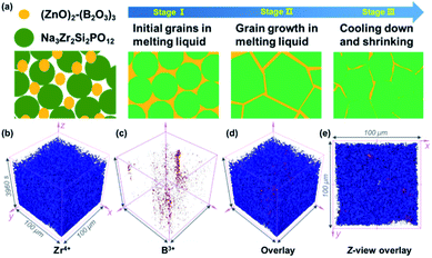
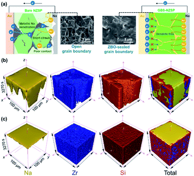
As shown in Fig. 1a, the GBS-NZSP solid electrolyte is synthesized through a liquid-phase sintering method using the ZBO additive whose melting point is 800.9 °C (Fig. S1†). Based on sintering theory, the ZBO additive melting provides a liquid-phase environment for pre-sintered Na3Zr2Si2PO12 grains, thus accelerates mass diffusion and promotes grain boundary reactivity.29,30 After cooling down and grain shrinkage, ZBO remains to fill the grain boundary. In this way, densification sintering of GBS-NZSP at a much lower temperature of 1000 °C than that of pristine NZSP (above 1250 °C) is realized. XRD patterns of GBS-NZSP samples with various ZBO molar ratios (x) of 0–0.3 are mainly indexed to the monoclinic Na3Zr2Si2PO12 phase structure of the c2/c space group (Fig. S2†). Diffraction peaks at 2θ = 24.04°, 24.44°, 28.12°, 31.44° correspond to (011), (110), (−111), and (111) planes of a monoclinic ZrO2 phase, which results from unreacted ZrO2 and minor sodium volatilization in high-temperature solid reactions.31 Additionally, for x = 0.3, there appears a new diffraction peak at 2θ = 26.99° belonging to the (200) plane of a tetragonal ZrSiO4 phase formed by the excess ZBO addition.30 Since there are no XRD diffraction peaks relevant to the ZBO additive, we consider that it is in a glassy state adhesive on the Na3Zr2Si2PO12 grains. This result is similar to the situation where a sodium borate-based additive is used.30–32 Given that B as a light element is difficult to be detected by energy dispersive X-ray spectrometry (EDS), we characterize the position of B by in-depth time of flight secondary ion mass spectrometry (ToF-SIMS). 3D rendered models according to the depth profile of GBS-NZSP (x = 0.2) by ToF-SIMS shown in Fig. 1b–e reveal that B3+ ions amorphously gather along the gaps of the Zr4+ bulk, indicating the existence of borate compounds at the grain boundary. Such a result agrees with the liquid-phase sintering theory, where the unreacted sintering additive is dissolved or dispersed at the grain boundary.29,30 Apparent densities of the samples are measured by the Archimedes drainage method to obtain the relative density against the theoretical density of monoclinic Na3Zr2Si2PO12 (3.244 g cm−3 at 25 °C).33 The relative density increases as the ZBO ratio increases from 0 to 0.2, and the highest relative density of 99.8% is reached, substantially higher than that of bare NZSP (73.7%) (Fig. S3†).We select SEM images of the GBS-NZSP sample with x = 0.2 and bare NZSP for comparison, among which NZSP contains loosely connected polyhedrons and gaps, while GBS-NZSP shows a denser microstructure (inset in Fig. 2a). When used in batteries for Na metal plating, the unsound NZSP undergoes uneven Na metal plating because of poor interfacial contact and Na accumulation at the grain boundary, which eventually leads to electron conductivity, Na dendrite formation and short circuits. In contrast, the densely sintered NZSP-ZBO allows high-flux and dendrite-free Na+-ion migration because of the GBS effect in reducing electron transfer and enhancing ionic conductivity at the grain boundary. As a result, stable Na plating and tight interfacial contact are achieved (Fig. 2a). Fig. 2(b) and (c) compare the 3D rendering models of positive ions based on the depth scan of NZSP and GBS-NZSP by ToF-SIMS after Na plating for over 6 h. The bare NZSP encounters unfavorable Na metal penetration into the solid electrolyte bulk, while GBS-NZSP possessing dense structure renders uniform Na metal plating on the surface without dendtrite formation.
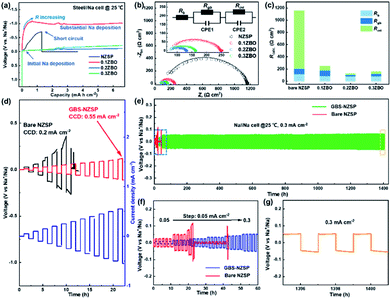
Galvanostatic Na plating curves of steel//Na cells using GBS-NZSP with an x variation of 0.1–0.3 and bare NZSP as solid electrolytes are collected at a current density of 0.1 mA cm−2. As shown in Fig. 3a, a rapid short circuit of NZSP occurs when the cell reaches a voltage of −0.71 V and a capacity of 1.28 mA h cm−2. For x = 0.1, the cell shows a sharp voltage ramp to −1.08 V at the initial stage and then the voltage gradually decreases to a plateau of around −0.98 V. Minor addition of ZBO shows a robust grain boundary effect and significantly improves the Na plating behaviour without fast short circuits. Further, for x = 0.2 and 0.3, the voltages of Na plating are much smaller, below 0.1 V even after a Na plating capacity of over 2.0 mA h cm−2 is achieved, indicating essentially reduced interfacial resistance and stability of GBS-NZSP against Na metal. Impressively, the optimal GBS-NZSP performs continuous Na plating with a capacity of up to 6.6 mA h cm−2 at a voltage as low as 0.11 V, exhibiting super ability of convenient Na plating at room temperature. Room-temperature electrochemical impedance spectroscopy (EIS) analysis of symmetrical Na//Na cells is conducted to clarify the interfacial resistance in the Na metal/solid electrolyte. Fig. 3b shows the Nyquist plots of the Na//Na cells using bare NZSP and GBS-NZSP (x = 0.1–0.3) as solid electrolytes measured at 25 °C. The inset is a suggested equivalent circuit according to previous literature,34 which contains three resistance components in series: bulk resistance (Rb), resistance at the grain boundary (Rgb) of the solid electrolyte and interfacial resistance (Rint) at the interface against Na metal. Fig. 3c shows the comparison of the as-calculated Rb, Rgb, and Rint between bare NZSP and GBS-NZSP (x = 0.1–0.3). For bare NZSP, Rb, Rgb, and Rint are calculated to be 117.7 Ω cm2, 85.0 Ω cm2, and 957.4 Ω cm2, respectively, giving a total resistance of 1160.1 Ω cm2. The symmetrical cells using GBS-NZSP (x = 0.1–0.3) solid electrolytes exhibit much lower resistance, demonstrating the significant effect of the GBS design by adding the ZBO additive into NZSP to simultaneously enhance both the grain boundary and the interfacial Na+-ion transport. Among them, GBS-NZSP (x = 0.2) exhibits the optimal electrochemical impedance nature and especially shows a desired low Rint of 23.3 Ω cm2, which is over 41 times smaller than that of bare NZSP and over 25 times smaller than that of a densely sintered NZSP-1250 (Fig. S4a†). Typically, we perform the critical current density (CCD) measurement under galvanostatic Na plating/stripping cycles. As shown in Fig. 3d, the CCD of GBS-NZSP (x = 0.2) is more than 2 times higher than that of NZSP, indicating improved stability for Na plating/stripping cycles. Further, long-term galvanostatic Na plating/stripping cycles are conducted in a symmetrical Na/GBS-NZSP/Na cell. The overall cycling profile during cycling for 1400 h is shown in Fig. 3e which exhibits stable and small polarization voltages under the stepwise current densities from 0.05 to 0.3 mA cm−2. Detailed cycling curves for the initial 0–60 h and the final 1395–1401 h are presented in Fig. 3f and g, respectively. There are no obvious voltage fluctuations at a continuously increasing current density from 0.05 to 0.3 mA cm−2 with 5 cycles for each step. The polarization voltage for reversible Na plating/stripping at 0.3 mA cm−2 is only 53 mV, which is well retained for as long as 1400 h. In comparison, the symmetrical cell using bare NZSP shows a large polarization voltage and rapid short circuit after cycling for 23 h at 0.15 mA cm−2. Moreover, the cycling profile of the symmetrical Na//Na cells using NZSP-1250, and GBS-NZSP at x = 0.1 and 0.3 as solid electrolytes is provided in Fig. S4,† none of which can maintain long-time stable Na plating/stripping cycling at a current density of over 0.2 mA cm−2. GBS-NZSP, which is synthesized by an energy-saving low-temperature sintering method and used without any post surface or chemical modification, exhibits excellent performance competitive with other solid electrolytes.15,18,24,25,28,35–38 A detailed comparison including the cell resistance, interfacial resistance, current density and stability is provided in Table S1† to further signify the advantage and novelty of the well-designed GBS-NZSP solid electrolyte for sodium metal batteries.
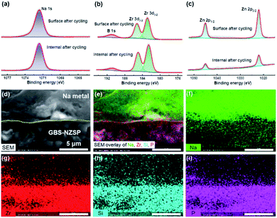
We disassemble the symmetrical cell to analyse the chemical states and morphology of GBS-NZSP (x = 0.2) after Na plating/stripping cycles for 1400 h. Typical Na 1s, B 1s, Zr 3d and Zn 2p spectra after cycling are exhibited in Fig. 4 with comparison between the upper surface and the internal section. The Na 1s spectra show no difference in the peak binding energy (1071.6 eV) between the surface and internal section (Fig. 4a). B 1s peaks at 190.9 eV are observed for both the surface and internal section, indicating the existence of B3+ in GBS-NZSP. The Zr 3d spectra split into two peaks at 185.3 and 182.9 eV, ascribed to Zr 3d3/2 and 3d1/2, respectively (Fig. 4b). Previous literature has reported reduced Zr(4−x)+ species on the surface of bare NZSP after Na plating/stripping cycles.15,22,39 Differently, here the cycled GBS-NZSP maintains Zr4+ without reduction on the surface, implying excellent chemical stability against the highly reductive Na metal. Reduced Zn(2−x)+ species are neither observed on the surface nor on the internal section (Fig. 4c), denying the formation of low-valence Zn compounds for unfavourable electron conductivity. The Si 2p, P 2p and O 1s spectra are presented in Fig. S4† to further support the point above. Therefore, it is indicated a stable interphase is formed between Na metal and GBS-NZSP, which suppresses reductive Na metal penetration into the solid electrolyte and facilitates uniform Na metal plating/stripping cycles. Cross-sectional morphology observation of Na metal caped GBS-NZSP is conducted by using a SEM equipped with an energy dispersive spectrometer (EDS). As shown in Fig. 4d, metallic Na maintains closely conformal contact with GBS-NZSP even after long-term cycling for 1400 h. Besides, the elemental mapping images shown in Fig. 4e–i indicate the intimate adhesion of metallic Na on the surface of GBS-NZSP and no Na dendrites are observed. It proves that not only the chemical composition of GBS-NZSP but also the desired interfacial contact is retained during Na plating/stripping cycles, explaining the super cycling stability and low interfacial resistance.
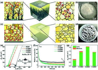
According to the discussion above, we describe the Na plating behaviour of the solid electrolytes shown in Fig. 5 with comparison between the unsound NZSP and the optimal GBS-NZSP. The former contains unclosed grain boundaries and pores, which become the bottlenecks of Na+-ion migration at high current densities. The blocked Na+ ions in these places then combine with electrons and Na plating subsequently occurs, breeding a curse for Na metal penetration across the solid electrolyte (Fig. 5a). Consequently, short circuits and mechanical breakdown of the solid electrolyte eventually take place (Fig. 5b). In sharp contrast, the well-designed GBS-NZSP allows high-flux Na+-ion migration and enables high-rate Na plating/stripping cycles without dendrite penetration (Fig. 5c and d). We measure the Nyquist plots of the solid electrolytes with ZBO content variation x = 0–0.3 by using sputtering Au films as blocking electrodes to obtain the total conductivity (σt) at room temperature. Fig. 5e shows the Nyquist plots calibrated by the surface areas of the solid electrolyte discs and the thicknesses (L) for x = 0, 0.1, 0.2, 0.3 are measured to be 0.107 mm, 0.101 mm, 0.090 mm, and 0.086 mm, respectively by using a micrometre. The total conductivities for x = 0, 0.1, 0.2, 0.3 are calculated to be 0.53 mS cm−1, 1.19 mS cm−1, 1.58 mS cm−1, and 1.13 mS cm−1, respectively through L/R. To clarify the contribution from electrons, polarization curves are further measured using a Au film as the blocking electrode and the result is shown in Fig. 5f. It is found that the current contribution by electron transfer decreases as the ZBO content increases. GBS-NZSP samples exhibit much lower electron currents than that of bare NZSP. As shown in Fig. 5g, GBS-NZSP (x = 0.2) exhibits the highest conductivity of 1.58 mS cm−1 with the smallest electron contribution of 1.8% at room temperature, while the electron contributions from bare NZSP, x = 0.1 and x = 0.3 are 15.3%, 7.1%, and 2.2%, respectively. This result supports the effect of GBS on hindering electron transfer and dendrite formation across the solid electrolyte.
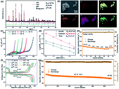
NASICON-type cathode materials for sodium ion batteries are advantageous because of their high Na+-ion conductivity, convenient structural design and excellent cycling stability.40–43 We assemble a solid-state sodium metal battery of Na3V1.5Cr0.5(PO4)3/GBS-NZSP/Na using a NASICON-type Na3V1.5Cr0.5(PO4)3 (NVCP) cathode synthesized through a sol–gel method.41 The retrieved refined XRD pattern of the as-synthesized NVCP is shown in Fig. 6a, confirming that NVCP belongs to a space group of R![[3 with combining macron]](https://www.rsc.org/images/entities/char_0033_0304.gif) c derived from a NASICON-type phase of Na3V2(PO4)3. Detailed cell parameters and atomic position data are provided in Table S2.† The SEM image along with the EDS mapping image shown in Fig. 6b indicates the existence of Na, V, Cr, P, and O uniformly distributed in NVCP micro-particles. Besides a polyvinylidene fluoride (PVDF) binder and carbon black conductive additive, a NaClO4-succinonitrile plastic crystal electrolyte (PCE) is further added as an ionic conductor additive for the composite NVCP cathode.44Fig. 6c shows the temperature-dependent Nyquist plots of the solid-state battery in the range of 25–60 °C, showing similarities of an increment on the Zr axis, two connected semicircles and a linear tail from a high frequency to a low frequency. The increment corresponds to the resistance of the GBS-NZSP solid electrolyte (RSE). The first semicircle is relevant with the anodic interface charge transfer (Rct,anodic), while the second semicircle is attributed to the cathodic one (Rct,cathodic). It is derived that Rct,anodic, Rct, cathodic and Rtotal at 25 °C are 75.9 Ω cm2, 71 Ω cm2 and 173.6 Ω cm2, respectively. The corresponding conductivity activation energies (Ea1, Ea2, and Ea3) are calculated to be 0.27 eV, 0.45 eV, and 0.33 eV, respectively (Fig. 6d). The small resistance and low activation energy signify the good temperature adaptability of the solid battery. Fig. 6e depicts the rate performance of the solid battery at stepwise rates in the range of 0.5–10C (1C = 121 mA g−1) at 25 °C. The first charge and discharge capacities are 126.5 and 119.1 mA h g−1, respectively, giving an initial coulombic efficiency of 94.2% higher than that of a liquid battery using the same cathode material.41,42 More importantly, the solid-state battery exhibits a satisfactory high-rate performance at 10C, showing a capacity of 108.1 mA h g−1 as high as over 89% that of the theoretical capacity.41,42 The charge/discharge profile at various rates is shown in Fig. 6f, consisting of two discharge plateaus of V5+/V4+ (3.92 V) and V4+/V3+ (3.20 V),41,42 which are retained when the rates are increased from 0.5C to 10C and then reset to 3C. The largest polarization between discharge and charge is only 0.34 V versus the charge plateau of 3.54 V, indicating a high energy storage efficiency of above 90%. Finally, we test long-term charge/discharge cycling performance at a rate of 10C. As shown in Fig. 6g, the initial capacity is 107.9 mA h g−1 of which 81% is retained after 560 cycles. A detailed comparison with other reported solid-state sodium batteries15,18,25,28,35 is provided in Table S3† to further emphasize the virtue of our GBS design, which provides promising application in solid-state metal batteries.
c derived from a NASICON-type phase of Na3V2(PO4)3. Detailed cell parameters and atomic position data are provided in Table S2.† The SEM image along with the EDS mapping image shown in Fig. 6b indicates the existence of Na, V, Cr, P, and O uniformly distributed in NVCP micro-particles. Besides a polyvinylidene fluoride (PVDF) binder and carbon black conductive additive, a NaClO4-succinonitrile plastic crystal electrolyte (PCE) is further added as an ionic conductor additive for the composite NVCP cathode.44Fig. 6c shows the temperature-dependent Nyquist plots of the solid-state battery in the range of 25–60 °C, showing similarities of an increment on the Zr axis, two connected semicircles and a linear tail from a high frequency to a low frequency. The increment corresponds to the resistance of the GBS-NZSP solid electrolyte (RSE). The first semicircle is relevant with the anodic interface charge transfer (Rct,anodic), while the second semicircle is attributed to the cathodic one (Rct,cathodic). It is derived that Rct,anodic, Rct, cathodic and Rtotal at 25 °C are 75.9 Ω cm2, 71 Ω cm2 and 173.6 Ω cm2, respectively. The corresponding conductivity activation energies (Ea1, Ea2, and Ea3) are calculated to be 0.27 eV, 0.45 eV, and 0.33 eV, respectively (Fig. 6d). The small resistance and low activation energy signify the good temperature adaptability of the solid battery. Fig. 6e depicts the rate performance of the solid battery at stepwise rates in the range of 0.5–10C (1C = 121 mA g−1) at 25 °C. The first charge and discharge capacities are 126.5 and 119.1 mA h g−1, respectively, giving an initial coulombic efficiency of 94.2% higher than that of a liquid battery using the same cathode material.41,42 More importantly, the solid-state battery exhibits a satisfactory high-rate performance at 10C, showing a capacity of 108.1 mA h g−1 as high as over 89% that of the theoretical capacity.41,42 The charge/discharge profile at various rates is shown in Fig. 6f, consisting of two discharge plateaus of V5+/V4+ (3.92 V) and V4+/V3+ (3.20 V),41,42 which are retained when the rates are increased from 0.5C to 10C and then reset to 3C. The largest polarization between discharge and charge is only 0.34 V versus the charge plateau of 3.54 V, indicating a high energy storage efficiency of above 90%. Finally, we test long-term charge/discharge cycling performance at a rate of 10C. As shown in Fig. 6g, the initial capacity is 107.9 mA h g−1 of which 81% is retained after 560 cycles. A detailed comparison with other reported solid-state sodium batteries15,18,25,28,35 is provided in Table S3† to further emphasize the virtue of our GBS design, which provides promising application in solid-state metal batteries.
Conclusions
In summary, we demonstrate a grain boundary sealed Na3Zr2Si2PO12 (GBS-NZSP) solid electrolyte synthesized by a liquid-phase sintering method using the (ZnO)2–(B2O3)3 additive to address the issues of high interfacial resistance and metal dendrite penetration. The GBS-NZSP possessing a dense microstructure and ZBO-strengthening grain boundary exhibits a desired interfacial resistance of as low as 23.3 Ω cm2 against Na metal and ultra-stable Na plating/stripping cycles at 0.3 mA cm−2 for 1400 h at room temperature. The satisfactory interfacial performance facilitates a solid-state sodium metal battery of Na3V1.5Cr0.5(PO4)3/GBS-NZSP/Na, which is featured with a low resistance of 175 Ω cm2 and exhibits superior electrochemical performance at room temperature. An initial coulombic efficiency of 94.2% and subsequent excellent high-rate capability are manifested from 0.5C to 10C. A high capacity of 108.1 mA h g−1 is delivered with 81% retention after 560 charge/discharge cycles at 10C rate. Our results present a well-designed Na+-ion solid electrolyte advantageous in application of solid metal batteries and promote the research advance of new-type solid-state batteries (i.e. solid-state Na–S, Na–O2, Na–CO2 batteries, etc.).Conflicts of interest
There are no conflicts to declare.Acknowledgements
This work was supported by Postdoctoral Science Foundation of China (2019M660474) and the National Natural Science Foundation of China (No. 52072033, 51772029, and 51972029).References
- H.-L. Yang, B.-W. Zhang, K. Konstantinov, Y.-X. Wang, H.-K. Liu and S.-X. Dou, Progress and Challenges for All-Solid-State Sodium Batteries, Adv. Energy Sustain. Res., 2021, 2(2), 2000057 CrossRef.
- Q. Zhao, S. Stalin, C.-Z. Zhao and L. A. Archer, Designing Solid-State Electrolytes for Safe, Energy-Dense Batteries, Nat. Rev. Mater., 2020, 5(3), 229–252 CrossRef CAS.
- A. Mauger, C. M. Julien, A. Paolella, M. Armand and K. Zaghib, Building Better Batteries in the Solid State: A Review, Mater, 2019, 12(23), 1–86 CrossRef PubMed.
- S. Lou, F. Zhang, C. Fu, M. Chen, Y. Ma, G. Yin and J. Wang, Interface Issues and Challenges in All-Solid-State Batteries: Lithium, Sodium, and Beyond, Adv. Mater., 2020, 2000721 Search PubMed.
- H. Liu, X.-B. Cheng, J.-Q. Huang, H. Yuan, Y. Lu, C. Yan, G.-L. Zhu, R. Xu, C.-Z. Zhao, L.-P. Hou, C. He, S. Kaskel and Q. Zhang, Controlling Dendrite Growth in Solid-State Electrolytes, ACS Energy Lett., 2020, 5(3), 833–843 CrossRef CAS.
- G. Liu, X. Sun, X. Yu, W. Weng, J. Yang, D. Zhou, R. Xiao, L. Chen and X. Yao, Na10SnSb2S12: A Nanosized Air-Stable Solid Electrolyte for All-Solid-State Sodium Batteries, Chem. Eng. J., 2021, 420, 127692 CrossRef CAS.
- Y. Kato, S. Hori, T. Saito, K. Suzuki, M. Hirayama, A. Mitsui, M. Yonemura, H. Iba and R. Kanno, High-Power All-Solid-State Batteries Using Sulfide Superionic Conductors, Nat. Energy, 2016, 1(4), 1–7 Search PubMed.
- E. A. Wu, S. Banerjee, H. Tang, P. M. Richardson, J. M. Doux, J. Qi, Z. Zhu, A. Grenier, Y. Li, E. Zhao, G. Deysher, E. Sebti, H. Nguyen, R. Stephens, G. Verbist, K. W. Chapman, R. J. Clement, A. Banerjee, Y. S. Meng and S. P. Ong, A Stable Cathode-Solid Electrolyte Composite for High-Voltage, Long-Cycle-Life Solid-State Sodium-Ion Batteries, Nat. Commun., 2021, 12(1), 1256 CrossRef CAS PubMed.
- L. Duchêne, D. H. Kim, Y. B. Song, S. Jun, R. Moury, A. Remhof, H. Hagemann, Y. S. Jung and C. Battaglia, Crystallization of Closo-Borate Electrolytes from Solution Enabling Infiltration into Slurry-Casted Porous Electrodes for All-Solid-State Batteries, Energy Storage Mater., 2020, 26, 543–549 CrossRef.
- R. Asakura, D. Reber, L. Duchêne, S. Payandeh, A. Remhof, H. Hagemann and C. Battaglia, 4 V Room-Temperature All-Solid-State Sodium Battery Enabled by a Passivating Cathode/Hydroborate Solid Electrolyte Interface, Energy Environ. Sci., 2020, 13(12), 5048–5058 RSC.
- B. Xu, X. Li, C. Yang, Y. Li, N. S. Grundish, P. H. Chien, K. Dong, I. Manke, R. Fang, N. Wu, H. Xu, A. Dolocan and J. B. Goodenough, Interfacial Chemistry Enables Stable Cycling of All-Solid-State Li Metal Batteries at High Current Densities, J. Am. Chem. Soc., 2021, 143(17), 6542–6550 CrossRef CAS PubMed.
- L. Ye and X. Li, A Dynamic Stability Design Strategy for Lithium Metal Solid State Batteries, Nature, 2021, 593(7858), 218–222 CrossRef CAS PubMed.
- B. Zahiri, A. Patra, C. Kiggins, A. X. B. Yong, E. Ertekin, J. B. Cook and P. V. Braun, Revealing the Role of the Cathode-Electrolyte Interface on Solid-State Batteries, Nat. Mater., 2021, 20(10), 1392–1400 CrossRef CAS PubMed.
- A. Banerjee, X. Wang, C. Fang, E. A. Wu and Y. S. Meng, Interfaces and Interphases in All-Solid-State Batteries with Inorganic Solid Electrolytes, Chem. Rev., 2020, 120(14), 6878–6933 CrossRef CAS PubMed.
- C. Wang, H. Jin and Y. Zhao, Surface Potential Regulation Realizing Stable Sodium/Na3Zr2Si2PO12 Interface for Room-Temperature Sodium Metal Batteries, Small, 2021, 17(23), 2100974 CrossRef CAS PubMed.
- J. Yang, G. Liu, M. Avdeev, H. Wan, F. Han, L. Shen, Z. Zou, S. Shi, Y.-S. Hu, C. Wang and X. Yao, Ultrastable All-Solid-State Sodium Rechargeable Batteries, ACS Energy Lett., 2020, 5(9), 2835–2841 CrossRef CAS.
- Q. Ma, C.-L. Tsai, X.-K. Wei, M. Heggen, F. Tietz and J. T. S. Irvine, Room Temperature Demonstration of a Sodium Superionic Conductor with Grain Conductivity in Excess of 0.01 S cm−1 and its Primary Applications in Symmetric Battery Cells, J. Mater. Chem. A, 2019, 7(13), 7766–7776 RSC.
- Y. Lu, J. A. Alonso, Q. Yi, L. Lu, Z. L. Wang and C. W. Sun, A High-Performance Monolithic Solid-State Sodium Battery with Ca2+ Doped Na3Zr2Si2PO12 Electrolyte, Adv. Energy Mater., 2019, 9(28), 1901205 CrossRef.
- X. Zhang, Q. Xiang, S. Tang, A. Wang, X. Liu and J. Luo, Long Cycling Life Solid-State Li Metal Batteries with Stress Self-Adapted Li/Garnet Interface, Nano Lett., 2020, 20(4), 2871–2878 CrossRef CAS PubMed.
- J. Meng, Y. Zhang, X. Zhou, M. Lei and C. Li, Li2CO3-Affiliative Mechanism for Air-Accessible Interface Engineering of Garnet Electrolyte via Facile Liquid Metal Painting, Nat. Commun., 2020, 11(1), 3716 CrossRef CAS PubMed.
- L. Liu, X. Qi, Q. Ma, X. Rong, Y. S. Hu, Z. Zhou, H. Li, X. Huang and L. Chen, Toothpaste-like Electrode: A Novel Approach to Optimize the Interface for Solid-State Sodium-Ion Batteries with Ultralong Cycle Life, ACS Appl. Mater. Interfaces, 2016, 8(48), 32631–32636 CrossRef CAS PubMed.
- S. Wang, H. Xu, W. Li, A. Dolocan and A. Manthiram, Interfacial Chemistry in Solid-State Batteries: Formation of Interphase and Its Consequences, J. Am. Chem. Soc., 2018, 140(1), 250–257 CrossRef CAS PubMed.
- H. Gao, S. Xin, L. Xue and J. B. Goodenough, Stabilizing a High-Energy-Density Rechargeable Sodium Battery with a Solid Electrolyte, Chem, 2018, 4(4), 833–844 CAS.
- Z. Gao, J. Yang, H. Yuan, H. Fu, Y. Li, Y. Li, T. Ferber, C. Guhl, H. Sun, W. Jaegermann, R. Hausbrand and Y. Huang, Stabilizing Na3Zr2Si2PO12/Na Interfacial Performance by Introducing a Clean and Na-Deficient Surface, Chem. Mater., 2020, 32(9), 3970–3979 CrossRef CAS.
- J. Yang, Z. Gao, T. Ferber, H. Zhang, C. Guhl, L. Yang, Y. Li, Z. Deng, P. Liu, C. Cheng, R. Che, W. Jaegermann, H. René and Y. Huang, Guided-Formation of a Favorable Interface for Stabilizing Na Metal Solid-State Batteries, J. Mater. Chem. A, 2020, 8(16), 7828–7835 RSC.
- X. Miao, H. Di, X. Ge, D. Zhao, P. Wang, R. Wang, C. Wang and L. Yin, AlF3-Modified Anode-Electrolyte Interface for Effective Na Dendrites Restriction in NASICON-Based Solid-State Electrolyte, Energy Storage Mater., 2020, 30, 170–178 CrossRef.
- W. Zhou, Y. Li, S. Xin and J. B. Goodenough, Rechargeable Sodium All-Solid-State Battery, ACS Cent. Sci., 2017, 3(1), 52–57 CrossRef CAS PubMed.
- X. Wang, J. Chen, D. Wang and Z. Mao, Improving the Alkali Metal Electrode/Inorganic Solid Electrolyte Contact via Room-Temperature Ultrasound Solid Welding, Nat. Commun., 2021, 12(1), 7109 CrossRef CAS PubMed.
- J. A. S. Oh, L. He, A. Plewa, M. Morita, Y. Zhao, T. Sakamoto, X. Song, W. Zhai, K. Zeng and L. Lu, Composite NASICON (Na3Zr2Si2PO12) Solid-State Electrolyte with Enhanced Na+ Ionic Conductivity: Effect of Liquid Phase Sintering, ACS Appl. Mater. Interfaces, 2019, 11(43), 40125–40133 CrossRef CAS PubMed.
- K. Noi, K. Suzuki, N. Tanibata, A. Hayashi and M. Tatsumisago, Liquid-Phase Sintering of Highly Na+ Ion Conducting Na3Zr2Si2PO12 Ceramics using Na3BO3 Additive, J. Am. Ceram. Soc., 2018, 101(3), 1255–1265 CrossRef CAS.
- K. Suzuki, K. Noi, A. Hayashi and M. Tatsumisago, Low Temperature Sintering of Na1+xZr2SixP3−xO12 by the Addition of Na3BO3, Scr. Mater., 2018, 145, 67–70 CrossRef CAS.
- Y. Zhao, C. Wang, Y. Dai and H. Jin, Homogeneous Na+ transfer dynamic at Na/Na3Zr2Si2PO12 Interface for All Solid-State Sodium Metal Batteries, Nano Energy, 2021, 88, 106293 CrossRef CAS.
- W. H. Baur, J. R. Dygas, D. H. Whitmore and J. Faber, Neutron Powder Diffraction Study and Ionic Conductivity oF Na2Zr2SiP2O12 and Na3Zr2Si2PO12, Solid State Ion., 1986, 18&19, 935–943 Search PubMed.
- T. Deng, X. Ji, Y. Zhao, L. Cao, S. Li, S. Hwang, C. Luo, P. Wang, H. Jia, X. Fan, X. Lu, D. Su, X. Sun, C. Wang and J. G. Zhang, Tuning the Anode-Electrolyte Interface Chemistry for Garnet-Based Solid-State Li Metal Batteries, Adv. Mater., 2020, 32(23), 2000030 CrossRef CAS PubMed.
- X. Miao, H. Wang, R. Sun, X. Ge, D. Zhao, P. Wang, R. Wang and L. Yin, Isotropous Sulfurized Polyacrylonitrile Interlayer with Homogeneous Na+ Flux Dynamics for Solid-State Na Metal Batteries, Adv. Energy Mater., 2021, 11(13), 2003469 CrossRef CAS.
- Z. Zhang, S. Wenzel, Y. Zhu, J. Sann, L. Shen, J. Yang, X. Yao, Y.-S. Hu, C. Wolverton, H. Li, L. Chen and J. Janek, Na3Zr2Si2PO12: A Stable Na+-Ion Solid Electrolyte for Solid-State Batteries, ACS Appl. Energy Mater., 2020, 3(8), 7427–7437 CrossRef CAS.
- H. Fu, Q. Yin, Y. Huang, H. Sun, Y. Chen, R. Zhang, Q. Yu, L. Gu, J. Duan and W. Luo, Reducing Interfacial Resistance by Na-SiO2 Composite Anode for NASICON-Based Solid-State Sodium Battery, ACS Mater. Lett., 2019, 2(2), 127–132 CrossRef.
- S. Song, H. M. Duong, A. M. Korsunsky, N. Hu and L. Lu, A Na+ Superionic Conductor for Room-Temperature Sodium Batteries, Sci. Rep., 2016, 6, 32330 CrossRef CAS PubMed.
- C. Wang, Z. Sun, Y. Zhao, B. Wang, C. Shao, C. Sun, Y. Zhao, J. Li, H. Jin and L. Qu, Grain Boundary Design of Solid Electrolyte Actualizing Stable All-Solid-State Sodium Batteries, Small, 2021, 17(40), 2103819 CrossRef CAS PubMed.
- Q. Wang, C. Ling, J. Li, H. Gao, Z. Wang and H. Jin, Experimental and Theoretical Investigation of Na4MnAl(PO4)3 Cathode Material for Sodium-Ion Batteries, Chem. Eng. J., 2021, 425, 130680 CrossRef CAS.
- Y. Zhao, X. Gao, H. Gao, H. Jin and J. B. Goodenough, Three Electron Reversible Redox Reaction in Sodium Vanadium Chromium Phosphate as a High-Energy-Density Cathode for Sodium-Ion Batteries, Adv. Funct. Mater., 2020, 30(10), 1908680 CrossRef CAS.
- Q. Wang, Y. Zhao, J. Gao, H. Geng, J. Li and H. Jin, Triggering the Reversible Reaction of V3+/V4+/V5+ in Na3V2(PO4)3 by Cr3+ Substitution, ACS Appl. Mater. Interfaces, 2020, 12(45), 50315–50323 CrossRef CAS PubMed.
- H. Gao, I. D. Seymour, S. Xin, L. Xue, G. Henkelman and J. B. Goodenough, Na3MnZr(PO4)3: A High-Voltage Cathode for Sodium Batteries, J. Am. Chem. Soc., 2018, 140(51), 18192–18199 CrossRef CAS PubMed.
- H. Gao, L. Xue, S. Xin, K. Park and J. B. Goodenough, A Plastic-Crystal Electrolyte Interphase for All-Solid-State Sodium Batteries, Angew. Chem., Int. Ed., 2017, 56(20), 5541–5545 CrossRef CAS PubMed.
Footnotes |
| † Electronic supplementary information (ESI) available. See DOI: 10.1039/d1ta10816f |
| ‡ These authors contributed equally. |
| This journal is © The Royal Society of Chemistry 2022 |

