Molecular packing and film morphology control in organic electrochemical transistors
Min
Zhu
 ,
Peiyun
Li
 ,
Jiu-Long
Li
 and
Ting
Lei
 *
*
Key Laboratory of Polymer Chemistry and Physics (MOE), School of Materials Science and Engineering, Peking University, Beijing 100871, China. E-mail: tinglei@pku.edu.cn
First published on 28th October 2021
Abstract
Organic electrochemical transistors (OECTs) based on conjugated polymers have aroused great interest in flexible bioelectronics due to their high transconductance, low operating voltage, and good biocompatibility. The OECT performance is mainly determined by the mixed ionic and electronic transport properties of organic semiconductors, which are largely influenced by the molecular packing and film morphology. To date, most efforts have been devoted to the development of new polymer structures. However, understanding the relationship among the chemical structure, molecular packing, film morphology, and OECT performance remains less explored. In this review, we provide an overview of recent advances in OECTs, with special emphasis on the relationship among the chemical structure, molecular packing, film morphology, and OECT performance. Finally, the challenges and prospects of OECTs are discussed as guidelines for future exploration.
Design, System, ApplicationOrganic electrochemical transistors (OECTs) based on conjugated polymers have attracted increasing interest in flexible bioelectronics due to their high transconductance, low operating voltage, and good biocompatibility. Recently, many efforts have been devoted to the improvement of the performance of OECTs by controlling the molecular packing and film morphology. Therefore, exploring the relationship among the molecular packing, film morphology, and OECT performance is necessary. Many studies have proved that the molecular packing and film morphology of intrinsic and doped conjugated polymers play a decisive role in device performance. Hence further improvement of the device performance requires a better understanding of the relationship among the molecular packing, film morphology, and device performance. Therefore, this minireview focuses on the strategies of molecular packing and film morphology control in OECTs in the past three years. It should be pointed out that these strategies are also applicable to other polymer electronics, such as organic thermoelectronics, organic field effect transistors, etc. This review is likely to be of interest to university researchers, engineers and graduate students in chemistry, materials science, bioelectronics, and electronic engineering who are willing to know about the strategies of polymer molecular packing and film morphology control in OECTs. |
1. Introduction
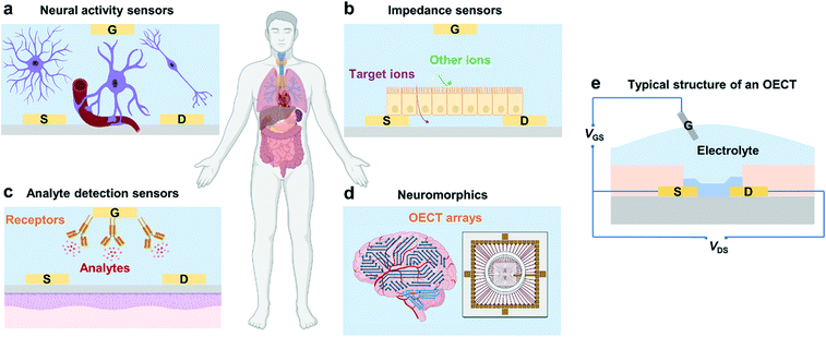
Organic electrochemical transistors (OECTs), as an emerging class of organic electronic devices, have been explored for a wide range of applications in bioelectronics for healthcare-related and biomedical applications due to their high transconductance, good stability in aqueous electrolytes, cytocompatibility, and facile biofunctionalization.1 For example, OECTs can detect cell activity after being interfaced with electrically active tissues and organs (Fig. 1a),2 act as impedance sensors to record changes in ion permeability (Fig. 1b),3 and serve as transducers in biosensors for the detection of electrolytes and metabolites (Fig. 1c).4,5 Besides, owing to their high transconductance and high ON/OFF ratios along with their low operation voltage, OECTs have also been applied in logic circuits, memory devices, and neuromorphic devices (Fig. 1d).6,7OECTs are three-terminal devices, where the drain and source terminals are electrically connected by a channel material (usually conjugated polymers), and the gate terminal is connected to the channel via an electrolyte (Fig. 1e).1 The mechanism of OECTs has been extensively studied over the past two decades.8 One of the well-recognized mechanisms is that OECTs exhibit an ionic and electronic transport ability during device operation.9 After ion injection, the polymer film will swell and form an electrolyte-rich and conjugated polymer-rich microphase, thus leading to mixed ionic–electronic transport.9
Similar to organic field-effect transistors (OFETs), OECTs belong to thin-film transistors and hence have similar device structures. However, OECTs use an electrolyte as the dielectric layer rather than a conventional dielectric with dipoles. The large volumetric capacitance endows OECTs with gate-channel capacitances of up to 9 mF cm−2, more than three orders of magnitude greater than that obtained with high-k dielectrics, which permits OECTs to operate at lower voltages (typically ∼0.5 V) and gives OECTs higher transconductance than OFETs. These characteristics endow OECTs with impressive signal amplification properties and make OECTs more suitable in sensors and bioelectronics.
The performance of an OECT device can be mainly assessed by transconductance (gm), which is the ratio of the current response to the applied voltage. In the saturation region, transconductance is given by:10
In the above formula, the product μC* has been recently proposed as a figure of merit for OECT materials,11 which can capture both the electronic and ionic transport properties of the channel materials regardless of the effects of the gate bias and device geometry. Therefore, it is essential to achieve high charge carrier mobility and high volumetric capacitance simultaneously for high-performance OECT materials. The high charge carrier mobility of conjugated polymers requires excellent intrachain and interchain charge carrier transport. Molecular packing, crystallinity, and domain connectivity strongly influence electron/hole mobility. Usually, tight molecular packing and smooth films with high film crystallinity are beneficial to high charge carrier mobility but have negative influences on ionic injection and transport. OECTs strongly rely on the ion injection from the electrolyte to change the film doping level and therefore the electrical conductivity of polymer films. The bulk doping of the channel through bulk gating facilitated by ion uptake yields a high capacitance. However, tight molecular packing and high crystallinity restrain the ion uptake. On the other hand, ion uptake irreversibly impacts the polymer packing and could cause a large film morphology change, which will consequently inhibit electron/hole transport.12 Therefore, the molecular packing and morphology should be carefully controlled to balance the trade-off between μ and C* in high-performance OECTs.
As a consequence of the complexity of the mixed ionic–electronic transport, the performance of OECTs sensitively depends on the molecular packing and film morphology. Hence, further improvement of the device performance requires a clear understanding of the relationship among the molecular packing, film morphology, and OECT performance. In this review, we briefly summarize the commonly used characterization methods for OECT films and computational approaches to understand this relationship. Then, we highlight recent progress on controlling the molecular packing and film morphology in OECTs and further reveal the relationship among the chemical structure, molecular packing, film morphology, and OECT performance.
2. Characterization methods and computational studies
The past decade has witnessed the fast development of OFET materials, and high charge carrier mobilities over 5 cm2 V−1 s−1 have been achieved for both p- and n-type conjugated polymers.13 Since OFETs have a similar device configuration and working principle to OECTs, after appropriate chemical modifications, many polymer FET materials can be used for OECTs.14 However, apart from enhancing the hydrophilicity of OFET materials, no general strategy has been established for designing high-performance OECT materials. One major reason is that the undesirable molecular packing and film morphology have largely impeded the materials from exhibiting their intrinsic properties. In general, molecular packing represents the local molecular arrangements through noncovalent interactions, spanning from the angstrom to nanometer scale. The morphology often refers to the surface appearance, including the domain size, texture and phase segregation.15 The molecular packing and morphology determine the charge/ion transport, ion uptake, and the ultimate device performance at different length scales. To better understand the structure–property relationship and optimize the device performance, it is crucial to characterize the polymer microstructures in an aqueous environment or after ion injection. Recently, many characterization methods have been used to probe the different aspects of polymer microstructures at different length scales. However, it remains an enormous challenge to accurately describe the polymer microstructures and morphology, especially in an aqueous environment or when ions are injected. New in situ technologies and characterization methods are desired.To fully reveal the mechanism of different polymers with different OECT performances, researchers have put forward several theoretical models to explain the phenomena observed during the experiments, which is good for handling increasingly more complicated systems.9 The synergy between the experimental characterization and theoretical studies greatly improved our understanding of how the molecular packing and film morphology affect the OECT performance. The developments in the study of how and why these microstructures and morphologies form will promote the development of novel synthetic materials for high-performance OECTs and specific OECT-related applications.
2.1 Characterization methods
The development and extensive use of characterization techniques allow us to determine the microstructures of polymers in a large range of length scales. For example, scanning probe techniques, optical spectroscopy, and X-ray scattering and diffraction, are commonly applied in the field of conjugated polymers.16 These techniques are also suitable for the characterization of the molecular packing and film morphology of polymer OECTs. Among them, atomic force microscopy (AFM), photo-induced force microscopy (PiFM), high-angle annular dark-field scanning transmission electron microscopy (HAADF-STEM), in situ electrochemical strain microscopy (ESM), grazing-incidence wide-angle X-ray scattering (GIWAXS), and electrochemical quartz crystal microbalance with dissipation monitoring (EQCM-D) are used frequently. Here, we briefly describe these techniques to understand their applications in OECTs.Scanning probe microscopy (SPM) provides a method to measure the nanoscale properties of materials. Depending on the type of probe used, a variety of properties can be measured including the surface morphology, surface potential, etc.16 The most commonly used SPM is AFM, which uses a sharp tip to scan across the surface of a film to obtain a high-resolution topographical image. AFM images can show the film surface morphology and provide roughness information.17 It can also be used to estimate the domain size and the size of phase separation. In OECTs, it is frequently used to qualitatively evaluate the crystallinity of the film and reveal the effects of electrochemical doping on the film morphology by comparing the changes in AFM images before and after electrochemical doping. Meanwhile for most organic semiconductor films, AFM usually does not have enough resolution to measure individual molecules since it is limited by many factors including the instrument's lateral positional accuracy, sharpness of the tip, and flatness of the sample.18 Hence other supplementary characterization techniques such as HAADF-STEM are used to image polymers with atomic resolution.19 For instance, Yoon et al. investigated the correlation between the film microstructural crystallinity and the OECT performance using pristine, ethylene glycol-treated (EG-P) and crystallized poly(3,4-ethylenedioxythiophene):poly(styrene sulfonate) (PEDOT:PSS) (Crys-P) films.20 AFM and HAADF-STEM images reveal that the Crys-P film contains more uniformly distributed nanopores than the EG-P film (Fig. 2a). Therefore, Crys-P provides a highly ordered crystallized polymer microstructure in combination with nanoscale pores, which is beneficial not only for efficient hole transport in the horizontal channel but also for unblocked ion permeation into conjugated moieties in the vertical direction, thus resulting in its high performance.
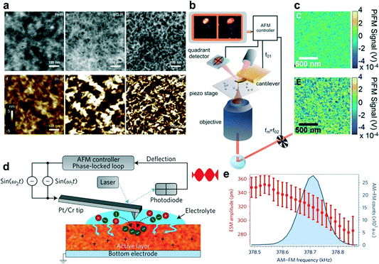 | ||
| Fig. 2 (a) The high-angle annular dark-field scanning transmission electron microscopy (HAADF-STEM) images of the Pr-P, EG-P, and Crys-P PEDOT:PSS films (top left to right) and the corresponding AFM images (bottom left to right). Reprinted with permission from ref. 20. Copyright 2018, Springer Nature. (b) and (c) Schematic diagram of a light force microscope (b) and PiFM images (c) of the unannealed (top) as well as annealed (bottom) P3MEEMT doped with PF6−. (d) and (e) Schematic diagram of an ESM using dual-amplitude resonance tracking centered on the contact resonance frequency (d) and ESM amplitude plotted as a function of AM–FM frequency, along with the corresponding AM–FM histogram data (e). Reprinted with permission from ref. 23. Copyright 2017, Macmillan Publishers Limited, part of Springer Nature. | ||
Another high-resolution SPM technique is PiFM, which starts as complete AFM, with a broadly tunable laser and necessary optics to focus the light from the laser on the tip–sample interface. Compared to traditional AFM, PiFM can operate with little or no tip–sample contact and relies on detecting the mechanical force on the tip instead of collecting scattered light (Fig. 2b). This advantage makes PiFM a naturally very high-resolution technique, routinely showing 10 nm resolution and an inherently high signal-to-noise ratio.21 Using PiFM, Ginger et al. studied the crystallinity, hydration, and dopant distribution of annealed and unannealed poly(3-{[2-(2-methoxyethoxy)ethoxy]methyl}thiophene-2,5-diyl) (P3MEEMT) films, respectively.22 PiFM maps the presence of anions within the film and reveals a large degree of dopant heterogeneity in crystalline P3MEEMT compared to that in amorphous P3MEEMT (Fig. 2c). They found that the crystalline and amorphous P3MEEMT films have very different hydration dynamics upon electrochemical doping. And they hypothesized that the hydration of the film disrupts the regions that link crystalline domains, thereby significantly decreasing the mobility in crystalline P3MEEMT. Amorphous P3MEEMT films have higher OECT mobility than those films with high crystallinity in OECTs. The more crystalline films are more susceptible to the disruption of electronic connectivity between crystalline regions due to ion uptake, leading to worse performance in OECTs.
In addition, to characterize the evolution of the film morphology before and after electrochemical doping, it is also necessary to achieve real-time monitoring of the film expansion during the electrochemical doping process. Hence, ESM is recently developed as a new real-time monitoring method. ESM can directly probe local variations in ionic transport in polymer devices by measuring subnanometer volumetric expansion due to ion uptake after electrochemical oxidation of the semiconductor (Fig. 2d). Ginger et al. used ESM to directly probe local ionic transport variations in poly(3-hexylthiophene) (P3HT).23 They found that the extent of the film morphology change decreases gradually with the increase of film stiffness, indicating that the ion and water injections decrease with the increase of polymer crystallinity (Fig. 2e). Hence, favorable polymer crystallinity is required for mixed electronic and ionic transport which is very different from OFETs. An OFET material with higher film crystallinity always shows higher charge carrier mobility because OFETs do not involve water and ion injection/diffusion processes.24
X-ray scattering technology is often used to extract the structural arrangement information, including the molecular packing, crystallinity, domain size, and orientation of the crystalline domains.15 Among them, GIWAXS is the most commonly used method. Two-dimensional (2D) GIWAXS plots can intuitively give the polymer orientation information, as well as a qualitative comparison of crystallinity. 1D plots can be used to analyze the change in the lamellar distance or the π–π stacking distance, and sometimes to estimate the grain size or coherence length. Yoon et al. used GIWAXS to study the detailed microstructures of pristine (Pr-P), ethylene glycol-treated (EG-P), and crystallized PEDOT:PSS (Crys-P) films.20 The 2D GIWAXS images showed that the Crys-P film exhibits significantly enhanced lamellar stacking, crystallinity, and highly anisotropic molecular ordering compared to the Pr-P and EG-P films. Besides, the vertical GIWAXS profile indicated that Crys-P has an obvious lamellar stacking along the out-of-plane direction. The horizontal GIWAXS profile showed that the Crys-P film exhibits a strong peak assigned to the π–π stacking along the in-plane direction (Fig. 3a). In operando GIWAXS measurements successfully reveal polymer microstructure evolution during electrochemical doping in an aqueous electrolyte environment. Ginger et al. showed that the reversible structural phase transition in PB2T-TEG occurred upon electrochemical oxidation.25 This result confirmed that the polymer lattice structures switched between distinct crystalline forms in a hydrated environment and significantly influenced mixed ionic–electronic transport.
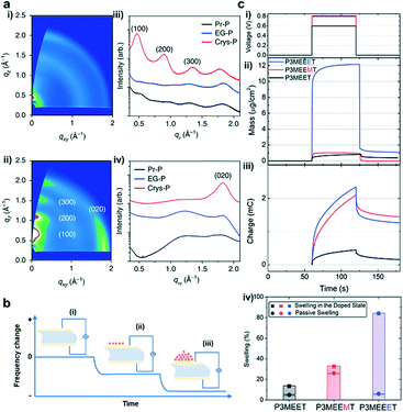 | ||
| Fig. 3 (a) (i) GIWAXS patterns obtained for 5% ethylene glycol-treated PEDOT:PSS (EG-P) and (ii) crystallized PEDOT:PSS (Crys-P) films; (iii) vertical and (iv) horizontal GIWAXS profiles of pristine PEDOT:PSS (Pr-P), EG-P, and Crys-P films. Reprinted with permission from ref. 20. Copyright 2018, Springer Nature. (b) Schematic representation of the principle of EQCM-D. (i) The quartz crystal oscillates at a constant frequency when an appropriate voltage is applied. (ii) The oscillation frequency begins to decrease as molecules begin to deposit on the crystal surface. (iii) The frequency further decreases as more molecules are deposited. (c) (i) Doping potential profile applied to the polymer films, 0.8 V for P3MEEMT and P3MEEET, as well as 0.6 V for P3MEET vs. Ag/AgCl. (ii) Mass change and (iii) the corresponding charge recorded as the polymers were doped. (iv) The swelling percentage of polymer films as they were exposed to the electrolyte and upon the application of the doping potential. Reprinted with permission from ref. 29. Copyright 2020, American Chemical Society. | ||
Since OECTs generally work in aqueous electrolytes, during the electrochemical doping process, water will diffuse into the polymer chains, causing the swelling of the film.26 The more water absorbed, the greater the change in the film morphology. Therefore, it is necessary to quantitatively characterize the water absorption of the film. EQCM-D is a surface-sensitive, label-free technology that measures mass changes at the surface with nanoscale resolution. The principle of EQCM-D is that adding or removing a small amount of material on the surface of the electrode will affect the oscillation frequency, which can be monitored in real time to obtain useful information about molecular interactions or reactions that occur on the electrode surface (Fig. 3b).27 Hence it can be used to detect the ion/water injection and extraction in OECTs.28 Based on EQCM-D, Thelakkat et al. monitored the difference in the water and ion uptake of polythiophene films without and under an applied potential. Using a Kelvin–Voigt viscoelastic model, the swelling behavior and mass uptake were carefully analyzed. They found that P3MEEET takes up 12 times more water and ions than P3MEET and P3MEEMT in the oxidized state (Fig. 3c), which correlated well with the volumetric capacitance.
2.2 Computational studies for molecular-scale understanding
The powerful characterization techniques mentioned above can give us an intuitive understanding of the molecular packing and film morphology of conjugated polymers in OECTs. Unfortunately, these tools cannot reveal some of the microscopic pictures, such as the local structure change at the subnanometer scale, the structure of the interface between the crystallites and amorphous regions, positions of counterions, etc. To address these issues, computational studies are often employed, which can further explain the experimental phenomenon and deepen our understanding of the structure–property relationships. Hence, massive attention has been paid to exploring the crystallization, degree of crystallinity, distribution of counterions, ion diffusion coefficients, doping concentration, type of electrolyte, and many other parameters related to the molecular packing and film morphology in OECT studies. These studies will deepen our understanding and accelerate the material design for high-performance OECTs.As one of the most studied conducting polymers, PEDOT-based polymers are frequently studied in theoretical modeling. For example, Zozoulenko et al. reported all atomistic molecular dynamics (MD) studies of the conducting polymer PEDOT doped with molecular counterions, tosylate (TOS), particularly emphasizing the role of water and making a comparison of the morphology of wet and dry films (Fig. 4a).30 The authors concluded that: (i) the size of the PEDOT crystallites depends on the water content, whereas the π–π stacking distance is independent of the chain length, charge concentration, and water content; (ii) the TOS counterion distribution depends on the charge concentration but is independent of the water content. These conclusions can well explain the changes in the film morphology of OECTs based on PEDOT:TOS before and after electrochemical doping, and remind researchers to pay more attention to the expansion caused by water during the electrochemical doping process. Apart from all atomistic MD simulations, they developed another computational tool, Martini coarse-grained MD model, which was more suitable for theoretical investigation of the morphology of conducting polymers on a scale exceeding tens of nanometers. The authors further investigated the diffusion coefficients of Na+ and Cl− ions in PEDOT:TOS using this tool.31 It was shown that the diffusion coefficients decrease exponentially as the hydration level and the doping level of PEDOT increase, which is related to the evolution of water clusters and trapping of ions around the polymer matrix as the hydration level changes (Fig. 4b). Simultaneously, they proved the reliability of these theoretical calculations through experiments and claimed that this rule was also suitable for doped polymers with molecular counterions including polypyrrole, polyaniline, thiophene, etc.
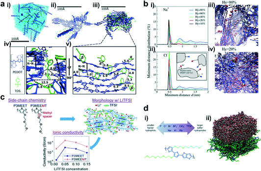 | ||
| Fig. 4 (a) (i) The molecular structure of PEDOT and TOS; (ii–iv) Snapshots of the PEDOT:TOS structures, where PEDOT is shown in blue, TOS in green, and water in light blue; (v) zoomed-in image of a representative crystallite from (iii). Reprinted with permission from ref. 30. Copyright 2017, American Chemical Society. (b) The distribution of the minimum distance d between (i) Na+ and Tos and (ii) Cl− and PEDOT for different hydration levels; (iii) one representative Cl− ion for Hy = 80% and (iv) two representative Cl− ions for Hy = 20%. Reprinted with permission from ref. 31. Copyright 2018, Owner Societies. (c) Chemical structures of P3MEET and P3MEEMT, schematic representation of LiTFSI distribution within the P3MEET/P3MEEMT semicrystalline structures, and comparison of the P3MEET and P3MEEMT ionic conductivities at 90 °C. Reprinted with permission from ref. 32. Copyright 2019, American Chemical Society. (d) (i) The scheme of anions and cations studied in this work (top), and the chemical structure of p(g2T-TT) (bottom). (ii) The simulated p(g2T-TT)–water interface. The side chain is shown as a green sphere, while the oligomer main chain is shown as a blue line. Reprinted with permission from ref. 33. Copyright 2020, American Chemical Society. | ||
Apart from PEDOT-based polymers, other high-performance polymers were also studied by theoretical modeling. For example, Patel et al. presented a combined computational and experimental study on the morphology and ionic transport in thin-film blends of polythiophene derivatives bearing oligoethylene glycol side chains (P3MEET and P3MEEMT) and lithium bis(trifluoromethanesulfonyl)imide (LiTFSI).32 MD simulations showed that adding a methylene spacer between the thiophene backbone and the first oxygen atom of the oligoethylene glycol side chain in P3MEEMT increased the mean square displacement and hence the segmental mobility of the three oxygen atoms in the side chains compared to the corresponding atoms in P3MEET (Fig. 4c). The higher segmental mobility of the side chains resulted in a better Li+ ionic transport in the amorphous regions and yielded a higher chance of Li+ ion-trapping cage formation in the crystalline regions. In both the P3MEEMT and P3MEET films, the ionic transport in the amorphous region dominated the ionic conductivity and generated a higher ionic conductivity in P3MEET. This study explains how the molecular structure influences the OECT performance and provides a platform to understand the role of the polymer structure, processing, and morphology in OECTs.
Since OECTs work in water-based solutions, the influence of the electrolyte on the OECT performance cannot be ignored. Rivnay et al. proved that choosing the appropriate electrolyte was crucial in achieving high-performance OECTs, since electrolytes could affect not only the doping/dedoping kinetics but also the electronic mobility.33 They used MD simulations on a series of p(g2T-TT)–electrolyte interfaces to analyze the effect of different counterions on the p(g2T-TT)–water interface and their ability to modulate the coordination and chelation of metal cations (Fig. 4d). They found that softer and more hydrophobic counterions will enhance the cation coordination and chelation by EG side chains. In contrast, harder and more hydrophilic cations tended to weaken this effect by increasing their solubility in water. This study illustrates that tailoring the electrolytes may be a viable strategy to tune the OECT performance for different applications.
3. Molecular packing and film morphology control
Both charge carrier transport and ion diffusion are crucial for a high-performance OECT material. Controlling the molecular packing and film morphology provides an essential strategy to optimize the charge carrier mobility and ion diffusion. A high-performance OECT polymer commonly requires: i) relatively good crystallinity, close molecular packing, and good connectivity between adjacent crystalline domains to obtain high charge carrier mobility, ii) enough space in the film and an efficient ionic transport path to promote the ability to accommodate and transport ions, and iii) capability to suppress the damage to film microstructures caused by ion uptake to reduce the detrimental influence of film swelling on the charge carrier transport. Some strategies have been reported to control the molecular packing and film morphology, such as modifying the polymer structures and optimizing the processing conditions. The chemical structure, backbone rigidity, and bulkiness of side groups highly affect the backbone conformation, polymer multi-level aggregation behavior, and the device performance.34 Altering the processing parameters can optimize the film crystallinity, surface morphology, and polymer chain orientation and thereby maximize the material performance. In the following parts, we review the molecular packing and film morphology control strategies from the perspective of chemical modification and processing methods.3.1 Modulating polymer packing by tuning backbone structures
Polymer packing is strongly affected by its backbone. It has been reported that altering the building blocks of the polymer backbone can regulate the energy level, backbone conformation, and interchain interactions, leading to different molecular packing. Nielsen et al. systematically studied the OECT performance of a series of semiconducting polythiophene-based polymers with various degrees of backbone curvature in which benzo[1,2-b:4,5-b′]-dithiophene (BDT) is either homopolymerized or copolymerized with thiophene or bithiophene (Fig. 5a).35 Grazing incidence wide-angle X-ray scattering (GIWAXS) measurements confirmed that along with the increase of the unsubstituted thiophene content in the backbone (gBDT to gBDT-2T), the orientation of polymer chains turned from a face-on to an edge-on orientation most likely due to the higher degree of aggregation behavior in solution (Fig. 5b). The edge-on-oriented polymer gBDT-2T favors in-plane charge transport and shows higher hole mobility, consequently benefitting better OECT performance.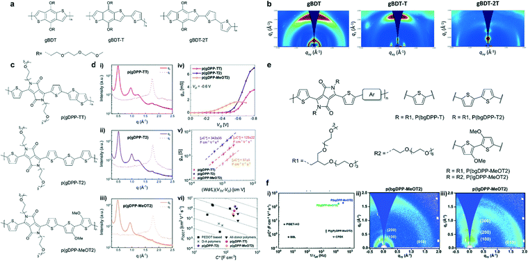 | ||
| Fig. 5 (a) Chemical structures of the BDT-based polymers. (b) GIWAXS plots for spin-cast films of the BDT-based polymers. Reprinted with permission from ref. 35. Copyright 2016, American Chemical Society. (c) Chemical structures of p(gDPP-TT), p(gDPP-T2) and p(gDPP-MeOT2). (d) In-plane and out-of-plane line cuts of (i) p(gDPP-TT), (ii) p(gDPP-T2) and (iii) p(gDPPMeOT2). (iv) Transconductance curves recorded for a single channel of p(gDPP-TT), p(gDPP-T2) and p(gDPP-MeOT2). (v) Extraction of μC* from (iii). (vi) Comparison of μ and C* values against other p-type OECT materials. Reprinted with permission from ref. 36. Copyright 2020, Wiley-VCH GmbH. (e) Chemical structures of DPP-based polymers with different donor moieties and grafted with linear or branched EG side chains. (f) (i) μC* vs. 1/τoff plots for p(lgDPPMeOT2), p(bgDPP-MeOT2), and other reported D–A polymers for OECTs. 2D GIWAXS images of (ii) p(bgDPP-MeOT2) and (iii) p(lgDPPMeOT2). Reprinted with permission from ref. 37. Copyright 2021, The Royal Society of Chemistry. | ||
Besides, donor–acceptor (D–A) polymers based on diketopyrrolopyrrole (DPP) in OECTs have been studied extensively. McCulloch et al. reported three thiophene-flanked DPP-based polymers with different donor units (Fig. 5c).36 Based on GIWAXS analysis, all three polymers displayed similar π–π stacking distances of around 3.55 ± 0.03 Å, lamellar distances of around 13 Å, and semicrystalline nature with a significant population of edge-on oriented crystallites. The absence of an out-of-plane scattering peak at ≈1.2 Å−1 in the methoxy-substituted polymer p(gDPP-MeOT2), may arise from scattering of the triethylene glycol side chains. p(gDPP-MeOT2) showed a lower degree of crystallinity compared to the other two polymers (Fig. 5d). This conclusion was consistent with the thin film UV-vis spectroscopy result, in which vibrational fine structures are absent in the case of p(gDPP-MeOT2). The methoxy substituent on the bithiophene unit disrupted the molecular packing, decreasing the π–π stacking coherence length and molecular ordering. A lowest mobility of 0.28 ± 0.04 cm2 V−1 s−1 for p(gDPP-MeOT2) was obtained. Partially attributed to its lowest mobility, p(gDPP-MeOT2) showed the lowest OECT performance with μC* of 57 F cm−1 V−1 s−1 among the three polymers (Fig. 5d). However, with the same backbone structure and longer/branched side-chain (Fig. 5e), Lei et al. found that MeOT2 was the best donor, and the μC* of the polymer could be optimized to 216 F cm−1 V−1 s−1 (Fig. 5f). Besides, they pointed out the difference in crystallinity, molecular packing, and response time between p(bgDPP-MeOT2) and p(lgDPP-MeOT2) (Fig. 5f). They emphasized that the strong electron-donating moiety, branched ethylene glycol chains, and optimized polymerization conditions were pivotal to obtain a high-performance D–A polymer for OECTs. This comparison revealed the complexity between alkoxy side chains and other factors for a D–A polymer in OECTs.
In addition to the polymer backbones mentioned above, other p-type polymer backbones like poly(3,4-ethylenedioxythiophene) (PEDOT) and poly(3-hexylthiophene-2,5-diyl) (P3HT) are also studied extensively,14 which we will not discuss in detail here.
Compared to the diverse structures in p-type polymers, only a few n-type polymers with high transconductance and water stability have been reported for OECTs.38–41 Poly(benzimidazobenzophenanthroline) (BBL) and naphthalene-1,4,5,8-tetracarboxylic-diimide-bithiophene (NDI-T2) based D–A copolymers (P-90) bearing ethylene glycol (EG) side chains are two kinds of widely studied systems for OECTs (Fig. 6a). Compared with P-90, ladder-type polymer BBL possesses a rigid planar backbone, edge-on packing, and a tight π–π stacking distance with no hydrophilic components to promote ionic transport. Surprisingly, Inal et al. revealed that BBL exhibits a superior OECT performance to P-90, largely due to its higher electron mobility and larger volumetric capacitance.42 Due to enough void space in the disorder regions, BBL films can take up water and ions upon electrochemical doping accompanied by a drastic and irreversible morphological change, leading to efficient ion-to-electron coupling. In contrast, P-90 only shows a moderate morphology change during doping and lower water/ion uptake (Fig. 6b). Charge carrier transport sensitively depends on the film morphology. During doping, water/ion infiltration usually destructs the molecular packing and film morphology, leading to a serious decrease in charge carrier mobility. For instance, the ex situ GIWAXS measurements suggest that a disruption of edge-on oriented crystallites and a decrease in π–π stacking coherence length occur in the electrochemically doped P-90, while BBL shows doping induced order improvement confirmed by a slight π–π stacking contraction and increased π–π stacking coherence length, which originates from its highly planar backbone, strong π–π interaction and the lack of hydrophilic side chains. Meanwhile, the rod-like long BBL backbone efficiently connects multiple crystallites across amorphous regions and avoids the disruption of the connectivity between the crystalline regions upon doping, facilitating the efficient interchain charge transport. Thus, BBL shows around one order of magnitude higher OECT mobility than P-90 (Fig. 6b). Therefore, the unique, rigid, side-chain-free polymers provide a promising strategy to bypass the trade-off between μOECT and C* parameters by achieving efficient charge interchain transport and electrolyte infiltration simultaneously.
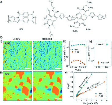 | ||
| Fig. 6 (a) Chemical structures of BBL and P-90. (b) (i–ii) AFM images of P-90 and BBL. The films were immersed in 0.1 m NaCl under different conditions: doped state at −0.8 V versus Ag/AgCl and de-doped back to the neutral state. (iii) The μC* product versus VG curve, (iv) the μOECT, and (v) film capacitance C versus the geometry of BBL and P90. Reprinted with permission from ref. 42. Copyright 2021, Wiley-VCH GmbH. | ||
3.2 Tuning polymer packing by side-chain engineering
Generally, side chains are tethered to the polymers or small molecules as solubilizing groups to promote their solubility in organic solvents and solution processability. Many studies have demonstrated that side chains can affect the molecular packing, film morphology, and hence the device performance besides solubility.43–45 Since water and ion diffusion/injection processes are needed in OECTs, many OECT materials need to introduce polar side chains (e.g. ethylene glycol) to enhance water/ion uptake. It has been proved that adjusting the type, density, length, distribution, and linkage of side chains can tailor the ion uptake and ensure high electrochemical doping and efficient charge carrier transport simultaneously, hence improving the OECT performance.After determining the polymer backbone, a suitable side chain is needed. In the design of mixed conduction materials for OECTs, replacing the alkyl side chains with ethylene glycol (EG) chains has proven to be a successful strategy to enhance ion infiltration and transport.46 Rivnay et al. reported that compared with thiophene-based polymer p(a2T-TT) bearing alkoxy side chains, the use of EG chains on the same backbone structure (p(g2T-TT)) can shift the operation mode from interfacial gating to bulk doping (Fig. 7a).47 p(g2T-TT) shows complete and reversible electrochromism and high volumetric capacitance at low operating voltages, which demonstrates that the EG side chains can facilitate hydration and ion penetration. A similar conclusion was also found in n-type polymers. McCulloch et al. presented that for random NDI-T2 copolymers (Fig. 7b), the ratio of alkyl chains and EG chains has a great influence on ion permeability and their performance in OECTs.48 The large percentages of glycol side chains increase the swelling of polymers in aqueous solutions, enhancing the uptake of ions and then the capacitance. The ESI measurements show that P-75, P-90, and P-100 exhibit more than an order of magnitude higher capacitance compared to P-0 and P-10 (Fig. 7c). The increased capacitance agrees with the transition from charge accumulation near the semiconductor–electrolyte interface to volumetric charging. However, the introduced glycol chains have an adverse effect on electron mobility. The addition of glycol side chains results in polymorph changes and increased paracrystalline disorder, noticeably decreasing the electron mobility. Ultimately, the increased volumetric capacitance C* of the polymer from P-50 to P-100 predominates the gradually enhanced transconductance (Fig. 7c). And P-90 and P-100 show the highest normalized gm of 0.210 and 0.204 S cm−1, respectively. All these results exhibit that the side chains play a significant role in the performance of OECTs.
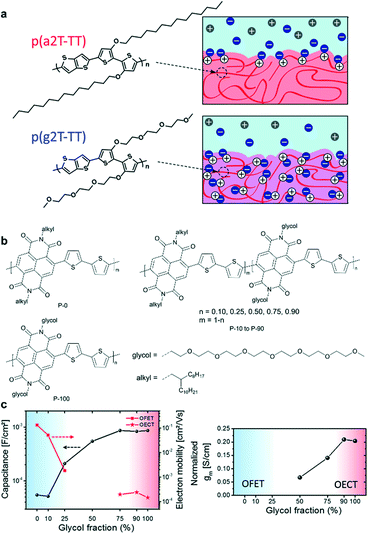 | ||
| Fig. 7 (a) Chemical structures and schematic of interactions of ions with p(a2T-TT) and p(g2T-TT). Cl− ions are shown in blue, Na+ in gray, and holes in white. Reprinted with permission from ref. 47. Copyright 2016, National Academy of Sciences of the United States of America. (b) Chemical structures of NDI-T2 copolymers with different ratios of alkyl chains and EG chains. (c) (left) Capacitance and electron mobility measurements of OFETs (P-0 to P-25) and OECTs (P-75 to P-100), and (right) normalized transconductance of the polymers. Reprinted with permission from ref. 48. Copyright 2018, American Chemical Society. | ||
Tuning the length of EG chains is another strategy to modulate the OECT performance. McCulloch et al. systematically investigated the structure–property relationship of a series of polythiophenes with pendant EG chains spanning two to six EG repeat units (Fig. 8a).49 According to GIWAXS measurements, p(g3T2-T) exhibits a high degree of lamellar ordering as well as a relatively high contribution of edge-on oriented crystallites, which benefits its charge transport properties (Fig. 8a). p(g3T2-T) has three EG side chains enabling favorable ion–polymer interactions. Because it has an appropriate EG chain length, p(g3T2-T) has the best OECT performance. In addition, the electrochemical doping-induced hydration effect must be taken into account when designing new OECT materials. Inal et al. studied a series of polymers bearing the same polymer backbone with an increasing percentage of EG side chains.50 AFM images suggest that the conjugated polymers experience significant changes in their structure and morphology during electrochemical doping. Polymers with high EG contents expand dramatically in the amorphous regions due to the heterogeneous water uptake, thus disrupting the electronic conductivity of the film and leading to OECTs with lower transconductance and slower response time (Fig. 8d). Therefore, it is crucial to choose a suitable EG chain length to gain a good mixed ionic–electronic transport.
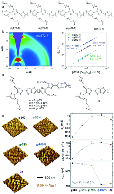 | ||
| Fig. 8 (a) Chemical structures of p(g2T2-T), p(g3T2-T), p(g4T2-T), and p(g6T2-T). (b) (left) 2D GIWAXS scattering patterns and line cuts of p(g3T2-T). (right) The plots of gm and μC* versus the channel geometry and operating parameters of p(g2T2-T), p(g3T2-T), and p(g4T2-T). Reprinted with permission from ref. 49. Copyright 2020, American Chemical Society. (c) Chemical structures of the polymers with different contents of EG side chains. (d) (left) 3D analysis of the films from the AFM data under doping at 0.5 V versus Ag/AgCl in 0.1 M NaCl (aq.). (right) gm, μC*, and τOECT plots of the polymers with different contents of EG side chains. Reprinted with permission from ref. 50. Copyright 2020, WILEY-VCH Verlag GmbH & Co. KGaA, Weinheim. | ||
Side-chain distribution is another important factor that needs to be carefully considered. To further enhance the OECT performance of polythiophene-based polymers, McCulloch et al. carefully tuned the pendant EG chains (Fig. 9a).51 According to the EQCM-D study, the polymers showed decreased active swelling upon going from p(g2T2-g4T2) to p(g0T2-g6T2), leading to a decrease in volumetric capacitance C*. This work confirmed that the side-chain distribution can significantly affect the polymer swelling capabilities and consequently the OECT stability with little effect on the electronic properties of the polymers (Fig. 9b).51 In addition, the change from linear EG chains to branched EG chains can also be used to tailor the solubility and crystallinity of the polymer. Lei et al. carefully compared the performance between p(bgDPP-MeOT2) with branched EG chains and p(lgDPP-MeOT2) with straight EG chains.37 They found that p(bgDPP-MeOT2) shows faster response speed and larger C* than p(lgDPP-MeOT2) (Fig. 5f). They attributed this phenomenon to the fact that p(bgDPP-MeOT2) displays less order packing compared with p(lgDPP-MeOT2) (Fig. 5f), which may promote better ion injection/ejection in the polymer bulk.
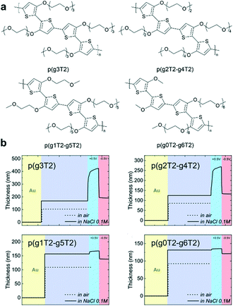 | ||
| Fig. 9 (a) Chemical structures of a series of polythiophenes with pendant EG chains spanning two to six EG repeat units. (b) EQCM-D traces recorded for p(g3T2), p(g2T2-g4T2), p(g1T2-g5T2), and p(g0T2-g6T2). Reprinted with permission from ref. 51. Copyright 2020, Wiley-VCH GmbH. | ||
Although EG chains are commonly used to enhance ionic transport, the damage to the ordered molecular packing and the reduced charge carrier mobility cannot be ignored. Compared to EG chains, the alkyl side chains have strong hydrophobicity, and hence introducing an alkyl group close to the backbone is considered a good way to protect the backbone.52 Therefore, seeking a great balance between the two side chains is crucial in OECTs. For example, hybrid alkyl–ethylene glycol side chains are recently introduced to enhance mixed electronic and ionic transport in OECTs, because moderate alkyl spaces can protect the polymer backbone from damage by ion and water injection. Thelakkat et al. investigated three polythiophene homopolymers (P3MEET, P3MEEMT, and P3MEEET) with differently linked (without and with methyl and ethyl spacers, respectively) diethylene glycol side chains (Fig. 10a).29 GIWAXS and AFM measurements indicate that P3MEEET possesses a semicrystalline feature with a preferential edge-on orientation and a good lamellar morphology, endowing P3MEEET with the highest μ (Fig. 10b). Besides, EG chains provide P3MEEET better accessibility and thus a higher C*. In addition to p-type polymers, introducing hybrid alkyl–ethylene glycol side chains is also suitable for n-type polymers. Giovannitti et al. investigated two naphthalene diimide-bithiophene (NDI-T2) copolymers functionalized with hybrid alkyl–glycol side chains (Fig. 10c).52 The NDI unit is segregated from the EG units within the side chain by an alkyl, propyl, or hexyl spacer to minimize detrimental swelling close to the conjugated backbone and balance the mixed conduction properties of polymers. They found that polymers functionalized with alkyl spacers show higher μC* and enhanced stability compared to those with EG-only side chains in OECTs (Fig. 10d), which highlights the effectiveness of using alkyl chain spacers to reduce the detrimental swelling of polymers in the electrochemical doping process.
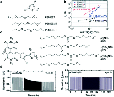 | ||
| Fig. 10 (a) Chemical structures of P3MEET, P3MEEMT, and P3MEEET. (b) The μC* product from the plot of gmversus the channel geometry and operation parameters. Reprinted with permission from ref. 29. Copyright 2020, American Chemical Society. (c) Chemical structures of NDI-T2 copolymers functionalized with hybrid alkyl–glycol side chains. (d) Stability pulsing measurements with alternating gate potentials between VG = 0 and 0.6 V for the polymer series with a pulse duration of 5 s for OECT channels biased at VD = 0.6 V in a 0.1 M NaCl aqueous solution under ambient conditions. Reprinted with permission from ref. 52. Copyright 2021, Wiley-VCH GmbH. | ||
4. Effects of processing conditions
Film processing plays a vital role in molecular packing and film morphology control in organic semiconductors, which has been widely studied in OFETs34 and organic photovoltaics (OPVs).53 Conjugated polymers are usually solution-processed by spin coating, dip-coating, or blade-coating, etc. The fluid flow of polymers can planarize the originally twisted polymer backbone to increase the conjugation length substantially. Therefore, it will cause a marked morphological transition from chiral, twinned domains to an achiral, highly aligned morphology, which will induce an increase in charge carrier mobilities.54 In addition, the solvent evaporation process will also impact the film morphology, thus affecting the device performance.55 Therefore, film processing conditions should be carefully explored to improve the performance of an OECT material.4.1 Solvents
Solvents not only dissolve the polymers for good solution processability but also play a significant role in controlling the polymer microstructures and film morphology. The solvent quality and solution concentration affect the solvent evaporation dynamics, polymer–solvent interactions, and solution-state microstructures.56 The solvent needs to be carefully selected for OECTs to boost the device performance. Inal et al. reported that the addition of a “bad” solvent (acetone) into a chloroform (CF)-based P-90 polymer solution increases the OECT transconductance more than three times by modifying the morphology.57 Perhaps resulting from the stronger aggregation tendency in the bad solvent, the P-90 film cast from 15 vol% acetone solution exhibits a rougher morphology with more hills and valleys on its surface than the pristine film (Fig. 11a). Such a rough surface may facilitate ion infiltration and thereby improve volumetric capacitance. As evidenced by the decrease of the in-plane and out-of-plane lamellar scattering in the 15 vol% acetone cast P-90 film, ions infiltrated into the polymers mostly reside in the side chain regions of both the edge-on and face-on crystallites and disrupt lamellar scattering. Meanwhile, the pristine P-90 film only displays decreased lamellar scattering along the in-plane direction. Moreover, strongly enhanced backbone scattering is observed in the electrochemically reduced film cast from the solution containing 15 vol% acetone, which suggests improved backbone ordering and better intrachain charge transport. As a result, careful solvent choice provides a simple yet efficient route to optimize the film morphology for enhanced mobility and volumetric capacitance (Fig. 11a).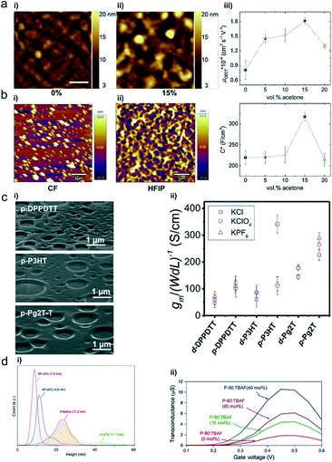 | ||
| Fig. 11 (a) AFM images of P-90 films cast from (i) 0 vol% and (ii) 15 vol% acetone in chloroform solution. (iii) Electron mobility (μOECT) and volumetric capacitance (C*) of the P-90 film as a function of acetone formulation content. Reprinted with permission from ref. 57. Copyright 2019, WILEY-VCH Verlag GmbH & Co. KGaA, Weinheim. (b) AFM topography images of the spin-coated p(bgDPP-MeOT2) film using (i) CF and (ii) HFIP as solvents. Reprinted with permission from ref. 37. Copyright 2021, The Royal Society of Chemistry. (c) (i) Porous film SEM images of p-DPPDTT, p-P3HT, and p-Pg2T-T. (ii) Normalized OECT transconductance peaks of these three polymers. Reprinted with permission from ref. 58. Copyright 2021, Wiley-VCH GmbH. (d) (i) Height distribution histograms and surface roughness root mean square (RMS) values. (ii) Transconductance of P-90 OECTs containing 0, 10, 40 and 80 mol% TBAF. Reprinted with permission from ref. 60. Copyright 2020, Springer Nature. | ||
In addition, Lei et al. found that solvents play an important role in regulating the polymers' aggregation state and controlling the molecular weight Mn of polymers.37 Conjugated polymers are visually dissolved in common aromatic or chlorinated solvents (e.g., o-DCB and CF) when characterizing the molecular weight, yet they usually show bimodular elution in gel permeation chromatography (GPC) measurements due to aggregation.48 However, when using hexafluoroisopropanol (HFIP) as eluent for molecular weight characterization, Lei et al. found that the Mn of DPP-based polymers is within the range of 26–30 kDa, much lower than that of 61–71 kDa based on the chloroform eluent. Besides, AFM images show that p(bgDPP-MeOT2) films based on CF have large chunks, whereas the films based on HFIP exhibit favorable network structures (Fig. 11b). These differences in molecular weight and film morphology lead to the differences in OECT performance (gm is usually smaller than 0.1 mS for p(bgDPP-MeOT2) using the spin-coating method). Besides, they further explored the universality of using HFIP for polythiophene with glycol side chains, e.g., p(g2T-T). Compared to other solvents (e.g., o-DCB, chlorobenzene (CB), CF, and 1,1,2,2-tetrachloroethane), HFIP provides better device performance. OECTs using HFIP show a μC* of 97 ± 8 F cm−1 V−1 s−1, higher than those using CF (72 ± 8 F cm−1 V−1 s−1).
4.2 Electrolyte–polymer interface engineering
The interface between the electrolyte (typically a liquid) and the active polymer (solid) is critical for OECTs since it directly affects the ion exchange between the two phases. Recently, Facchetti et al. produced porous polymer films with controlled morphologies, which dramatically enhanced the OECT properties of polymers without hydrophilic side chains (Fig. 11c).58 Under humid conditions, solvent evaporation during the spin-coating process leads to the condensation of water droplets onto the solution surface. Subsequently, a film with porous structures is obtained after complete evaporation of water and solvent. The porous films have randomly distributed pores with a feature size of ∼200–1000 nm (Fig. 11c), and the pore shape/depth varies with the polymer architectures. Because of efficient electrochemical doping and large interfacial area, these porous films achieve fast ion intercalation/de-intercalation, high transconductance, high volumetric capacitance, and low subthreshold swing. Thus, this work provides an efficient strategy to enhance the OECT properties of hydrophobic polymers.4.3 Additives
Additives have long been used in organic solar cells to adapt the morphology and control the crystallinity, improving molecular ordering and hence electronic properties.59 Similarly, additives can also be used to improve the performance of OECTs. Inal et al. found that mixing an ammonium salt, tetra-n-butylammonium fluoride (TBAF), with the n-type conjugated polymer P-90 results in water-stable n-doping and morphology effects, simultaneously improving the channel capacitance and mobility and thus improving the transconductance (Fig. 11d).60 The addition of TBAF has no adverse effect on the polymer microstructure and crystallinity but can alter the film morphology by changing the surface texture and polymer aggregates. AFM images reveal that TBAF smoothens the P-90 film morphology with decreased surface root-mean-square (RMS) roughness (Fig. 11d). Furthermore, the authors hypothesize that TBAF may eliminate the grain boundary, densify the semiconducting layer, and potentially facilitate easier ionic transport in the polymer film.Conclusion and outlook
This review summarizes the methods used to investigate the molecular packing and film morphology in OECTs and strategies to control them. From the discussions above, we try to give the readers a better understanding of the relationship among the chemical structure, molecular packing, film morphology, and OECT performance. Carefully controlling the molecular packing and film morphology has been proven to be a feasible avenue to overcome the troublesome trade-off between μ and C* in OECTs. Although the past decade has witnessed the rapid development of OECTs, there are still many challenges, and the performance of OECT materials also needs to be further improved. We believe that more efforts are needed for the following aspects.(1) Achieving the best balance between the charge carrier mobility and ionic transport. Different from OFETs, OECTs involve solvent swelling and the ion uptake process, resulting in a more complex working principle. The troublesome trade-off between μ and C* in OECTs is crucial for enhancing the OECT performance. A further understanding of the electronic and ionic transport mechanism seems essential to reveal the basic principle of OECTs and optimize the device performance. More recently, molecular packing modulation and film morphology control have been proved to be feasible methods to overcome the troublesome trade-off between μ and C*. Besides structure modification, process engineering can establish efficient methods for optimizing charge/ion transport and simultaneously improving both μ and C*.
(2) More advanced characterization techniques. Accurately describing the polymer microstructures and morphology remains a huge challenge, such as the polymer microstructures in amorphous regions and the position of the ions in the film. In addition, it is urgent to develop new film morphology characterization methods that can characterize polymers in complex situations, such as the in-situ monitoring of the dynamic electrochemical doping process in an electrolyte or under an applied voltage. This requires researchers to make appropriate modifications to the regular test equipment to meet the needs of OECT testing. More technologies with high resolution and real-time monitoring, such as HAADF-STEM, PiFM and in operando GIWAXS, are expected to provide clear evolution of the microstructure and morphology during electrochemical doping.
(3) Computational studies to better simulate the operating environment of OECTs. Conventional characterization techniques fail to observe some of the microscopic pictures, for instance local structure changes at the subnanometer scale. Computational studies can be employed to understand the molecular-scale features and reveal the structure–property relationship. However, the current computational methods are greatly simplified and primarily used for some small systems such as PEDOT-based systems. Even if some studies introduce a layer of water molecules on the polymer surface, there is no better calculation method to introduce the whole water surroundings into the calculation process, greatly reducing the reliability of the calculation results. Therefore, more calculation models that can simulate the more realistic working conditions of the polymer needs to be explored in the future.
(4) New approaches for fine-tuning the molecular packing and film morphology. Most studies focus on chemical modifications, whereas few studies are devoted to understanding the mechanisms of different processing methods. For example, several studies have shown that solvents have a significant effect on the performance of OECTs. However, there is currently no study revealing how solvents regulate the molecular arrangement and film morphology of polymers to affect the performance of OECTs. A further understanding of the solvent effects on the solution-state aggregation and thin-film morphology is urgently needed. More effective processing methods, like thermal annealing, exposure to solvent vapors, tuning the solvent quality, and using morphology-additives, are expected to enhance the performance of OECTs further.
(5) Realizing the practical applications of OECTs. The obstacles restricting the practical applications of OECTs mainly include the challenge of realization of CMOS-like logic circuits and their slow response speed. Firstly, the performance of n-type OECT materials is far lower than that of p-type OECT materials, thus precluding the realization of advanced CMOS-like circuits. Hence high-performance n-type OECT materials are urgently needed. N-type polymers with high electronic affinities and rigid coplanar structures are promising to obtain superior water stability and electron mobility, which are desired for high-performance n-type OECTs. Secondly, it is worth noting that compared with OFETs, OECTs have slower response speeds because of the slower ionic transport. In OECTs, the response time (τ) includes the switching on time (τon) and the switching off time (τoff), which are usually more than 100 μs. Hence they are not suitable for applications requiring real-time sensing and high-speed devices, such as electroencephalogram (EEG) measurement. However, there are very few effective methods for improving the response time of OECTs. Hydrophilic modification of polymers and film morphology control are efficient avenues to improve the polymer swelling and ion diffusion, which are beneficial for fast signal capturing.
Recently, the field of OECTs has been developing rapidly and gradually conquered the challenges mentioned above. We believe that with an in-depth understanding of the relationship among the molecular packing, film morphology, and OECT performance, the performance of OECTs will be further improved, and OECTs will exhibit their unique role in the field of wearable and implantable electronics soon.
Conflicts of interest
The authors declare that they have no conflicts of interest.Acknowledgements
This work is supported by Beijing Municipal Natural Science Foundation (2192020), National Natural Science Foundation of China (22075001), and State Key Laboratory of Luminescent Materials and Devices (2021-skllmd-02).References
- J. Rivnay, S. Inal, A. Salleo, R. M. Owens, M. Berggren and G. G. Malliaras, Nat. Rev. Mater., 2018, 3, 17086 CrossRef CAS.
- A. Williamson, M. Ferro, P. Leleux, E. Ismailova, A. Kaszas, T. Doublet, P. Quilichini, J. Rivnay, B. Rózsa, G. Katona, C. Bernard and G. G. Malliaras, Adv. Mater., 2015, 27, 4405–4410 CrossRef CAS.
- G. Spyropoulos, J. N. Gelinas and D. Khodagholy, Sci. Adv., 2019, 5, eaau7378 CrossRef CAS.
- M. Braendlein, A. M. Pappa, M. Ferro, A. Lopresti, C. Acquaviva, E. Mamessier, G. G. Malliaras and R. M. Owens, Adv. Mater., 2017, 29, 1605744 CrossRef.
- P. Li, T. Lei and L. Ding, Sci. Bull., 2020, 65, 1141–1143 CrossRef CAS.
- W. Lee, D. Kim, J. Rivnay, N. Matsuhisa, T. Lonjaret, T. Yokota, H. Yawo, M. Sekino, G. G. Malliaras and T. Someya, Adv. Mater., 2016, 28, 9722–9728 CrossRef CAS PubMed.
- Y. van de Burgt, E. Lubberman, E. J. Fuller, S. T. Keene, G. C. Faria, S. Agarwal, M. J. Marinella, A. Alec Talin and A. Salleo, Nat. Mater., 2017, 16, 414–418 CrossRef CAS PubMed.
- J. T. Friedlein, R. R. McLeod and J. Rivnay, Org. Electron., 2018, 63, 398–414 CrossRef CAS.
- B. D. Paulsen, K. Tybrandt, E. Stavrinidou and J. Rivnay, Nat. Mater., 2020, 19, 13–26 CrossRef CAS.
- J. Rivnay, P. Leleux, M. Ferro, M. Sessolo, A. Williamson, D. A. Koutsouras, D. Khodagholy, M. Ramuz, X. Strakosas, R. M. Owens, C. Benar, J.-M. Badier, C. Bernard and G. G. Malliaras, Sci. Adv., 2015, 1, e1400251 CrossRef PubMed.
- S. Inal, G. G. Malliaras and J. Rivnay, Nat. Commun., 2017, 8, 1767 CrossRef.
- A. Savva, C. Cendra, A. Giugni, B. Torre, J. Surgailis, D. Ohayon, A. Giovannitti, I. McCulloch, E. Di Fabrizio, A. Salleo, J. Rivnay and S. Inal, Chem. Mater., 2019, 31, 927–937 CrossRef CAS.
- J. Yang, Z. Zhao, S. Wang, Y. Guo and Y. Liu, Chem, 2018, 4, 2748–2785 CAS.
- E. Zeglio and O. Inganäs, Adv. Mater., 2018, 30, 1800941 CrossRef PubMed.
- J. Rivnay, S. C. B. Mannsfeld, C. E. Miller, A. Salleo and M. F. Toney, Chem. Rev., 2012, 112, 5488–5519 CrossRef CAS.
- A. Salleo, R. J. Kline, D. M. DeLongchamp and M. L. Chabinyc, Adv. Mater., 2010, 22, 3812–3838 CrossRef CAS PubMed.
- C. F. Q. G. Binnig and Ch. Gerber, Phys. Rev. Lett., 1986, 56, 930 CrossRef PubMed.
- M. Xiong, J.-Y. Wang and J. Pei, Org. Mater., 2021, 03, 001–016 CrossRef CAS.
- C. Kübel, A. Voigt, R. Schoenmakers, M. Otten, D. Su, T. C. Lee, A. Carlsson and J. Bradley, Microsc. Microanal., 2005, 11, 378–400 CrossRef.
- S.-M. Kim, C.-H. Kim, Y. Kim, N. Kim, W.-J. Lee, E.-H. Lee, D. Kim, S. Park, K. Lee, J. Rivnay and M.-H. Yoon, Nat. Commun., 2018, 9, 3858 CrossRef PubMed.
- J. Jahng, J. Brocious, D. A. Fishman, F. Huang, X. Li, V. A. Tamma, H. K. Wickramasinghe and E. O. Potma, Phys. Rev. B: Condens. Matter Mater. Phys., 2014, 90, 155417 CrossRef.
- L. Q. Flagg, C. G. Bischak, J. W. Onorato, R. B. Rashid, C. K. Luscombe and D. S. Ginger, J. Am. Chem. Soc., 2019, 141, 4345–4354 CrossRef CAS PubMed.
- R. Giridharagopal, L. Q. Flagg, J. S. Harrison, M. E. Ziffer, J. Onorato, C. K. Luscombe and D. S. Ginger, Nat. Mater., 2017, 16, 737–742 CrossRef CAS.
- Z. F. Yao, J. Y. Wang and J. Pei, Chem. Sci., 2020, 12, 1193–1205 RSC.
- C. G. Bischak, L. Q. Flagg, K. Yan, T. Rehman, D. W. Davies, R. J. Quezada, J. W. Onorato, C. K. Luscombe, Y. Diao, C. Z. Li and D. S. Ginger, J. Am. Chem. Soc., 2020, 142, 7434–7442 CrossRef CAS PubMed.
- J. Gladisch, E. Stavrinidou, S. Ghosh, A. Giovannitti, M. Moser, I. Zozoulenko, I. McCulloch and M. Berggren, Adv. Sci., 2020, 7, 1901144 CrossRef CAS.
- S. Neupane, Y. De Smet, F. U. Renner and P. Losada-Pérez, Front. Mater., 2018, 5, 46 CrossRef.
- M. Edvardsson, S. Svedhem, G. Wang, R. Richter, M. Rodahl and B. Kasemo, Anal. Chem., 2009, 81, 349–361 CrossRef CAS PubMed.
- P. Schmode, A. Savva, R. Kahl, D. Ohayon, F. Meichsner, O. Dolynchuk, T. Thurn-Albrecht, S. Inal and M. Thelakkat, ACS Appl. Mater. Interfaces, 2020, 12, 13029–13039 CrossRef CAS.
- J. F. Franco-Gonzalez and I. V. Zozoulenko, J. Phys. Chem. B, 2017, 121, 4299–4307 CrossRef CAS PubMed.
- M. Modarresi, J. F. Franco-Gonzalez and I. Zozoulenko, Phys. Chem. Chem. Phys., 2018, 20, 17188–17198 RSC.
- B. X. Dong, C. Nowak, J. W. Onorato, J. Strzalka, F. A. Escobedo, C. K. Luscombe, P. F. Nealey and S. N. Patel, Chem. Mater., 2019, 31, 1418–1429 CrossRef CAS.
- M. Matta, R. Wu, B. D. Paulsen, A. J. Petty, R. Sheelamanthula, I. McCulloch, G. C. Schatz and J. Rivnay, Chem. Mater., 2020, 32, 7301–7308 CrossRef CAS.
- Q. Y. Li, Z. F. Yao, J. Y. Wang and J. Pei, Rep. Prog. Phys., 2021, 84, 076601 CrossRef CAS.
- C. B. Nielsen, A. Giovannitti, D.-T. Sbircea, E. Bandiello, M. R. Niazi, D. A. Hanifi, M. Sessolo, A. Amassian, G. G. Malliaras, J. Rivnay and I. McCulloch, J. Am. Chem. Soc., 2016, 138, 10252–10259 CrossRef CAS PubMed.
- M. Moser, A. Savva, K. Thorley, B. D. Paulsen, T. C. Hidalgo, D. Ohayon, H. Chen, A. Giovannitti, A. Marks, N. Gasparini, A. Wadsworth, J. Rivnay, S. Inal and I. McCulloch, Angew. Chem., 2021, 60, 7777–7785 CrossRef CAS.
- H. Jia, Z. Huang, P. Li, S. Zhang, Y. Wang, J.-Y. Wang, X. Gu and T. Lei, J. Mater. Chem. C, 2021, 9, 4927–4934 RSC.
- V. Rubio-Giménez, M. Galbiati, J. Castells-Gil, N. Almora-Barrios, J. Navarro-Sánchez, G. Escorcia-Ariza, M. Mattera, T. Arnold, J. Rawle, S. Tatay, E. Coronado and C. Martí-Gastaldo, Adv. Mater., 2018, 30, 1704291 CrossRef.
- A. Giovannitti, C. B. Nielsen, D.-T. Sbircea, S. Inal, M. Donahue, M. R. Niazi, D. A. Hanifi, A. Amassian, G. G. Malliaras, J. Rivnay and I. McCulloch, Nat. Commun., 2016, 7, 13066 CrossRef CAS PubMed.
- J. Jin, G. Long, Y. Gao, J. Zhang, C. Ou, C. Zhu, H. Xu, J. Zhao, M. Zhang and W. Huang, ACS Appl. Mater. Interfaces, 2019, 11, 1109–1116 CrossRef CAS PubMed.
- E. Zeglio, M. Vagin, C. Musumeci, F. N. Ajjan, R. Gabrielsson, X. T. Trinh, N. T. Son, A. Maziz, N. Solin and O. Inganäs, Chem. Mater., 2015, 27, 6385–6393 CrossRef CAS.
- J. Surgailis, A. Savva, V. Druet, B. D. Paulsen, R. Wu, A. Hamidi-Sakr, D. Ohayon, G. Nikiforidis, X. Chen, I. McCulloch, J. Rivnay and S. Inal, Adv. Funct. Mater., 2021, 31, 2010165 CrossRef CAS.
- T. Lei, J.-Y. Wang and J. Pei, Chem. Mater., 2014, 26, 594–603 CrossRef CAS.
- J. Mei and Z. Bao, Chem. Mater., 2014, 26, 604–615 CrossRef CAS.
- Y. Yang, Z. Liu, G. Zhang, X. Zhang and D. Zhang, Adv. Mater., 2019, 31, 1903104 CrossRef CAS PubMed.
- B. Meng, J. Liu and L. Wang, Polym. Chem., 2020, 11, 1261–1270 RSC.
- A. Giovannitti, D.-T. Sbircea, S. Inal, C. B. Nielsen, E. Bandiello, D. A. Hanifi, M. Sessolo, G. G. Malliaras, I. McCulloch and J. Rivnay, Proc. Natl. Acad. Sci. U. S. A., 2016, 113, 12017–12022 CrossRef CAS PubMed.
- A. Giovannitti, I. P. Maria, D. Hanifi, M. J. Donahue, D. Bryant, K. J. Barth, B. E. Makdah, A. Savva, D. Moia, M. Zetek, P. R. F. Barnes, O. G. Reid, S. Inal, G. Rumbles, G. G. Malliaras, J. Nelson, J. Rivnay and I. McCulloch, Chem. Mater., 2018, 30, 2945–2953 CrossRef CAS PubMed.
- M. Moser, L. R. Savagian, A. Savva, M. Matta, J. F. Ponder, T. C. Hidalgo, D. Ohayon, R. Hallani, M. Reisjalali, A. Troisi, A. Wadsworth, J. R. Reynolds, S. Inal and I. McCulloch, Chem. Mater., 2020, 32, 6618–6628 CrossRef CAS.
- A. Savva, R. Hallani, C. Cendra, J. Surgailis, T. C. Hidalgo, S. Wustoni, R. Sheelamanthula, X. Chen, M. Kirkus, A. Giovannitti, A. Salleo, I. McCulloch and S. Inal, Adv. Funct. Mater., 2020, 30, 1907657 CrossRef CAS.
- M. Moser, T. C. Hidalgo, J. Surgailis, J. Gladisch, S. Ghosh, R. Sheelamanthula, Q. Thiburce, A. Giovannitti, A. Salleo, N. Gasparini, A. Wadsworth, I. Zozoulenko, M. Berggren, E. Stavrinidou, S. Inal and I. McCulloch, Adv. Mater., 2020, 32, 2002748 CrossRef CAS PubMed.
- I. P. Maria, B. D. Paulsen, A. Savva, D. Ohayon, R. Wu, R. Hallani, A. Basu, W. Du, T. D. Anthopoulos, S. Inal, J. Rivnay, I. McCulloch and A. Giovannitti, Adv. Funct. Mater., 2021, 31, 2008718 CrossRef CAS.
- H. Lee, C. Park, D. H. Sin, J. H. Park and K. Cho, Adv. Mater., 2018, 30, 1800453 CrossRef PubMed.
- K. S. Park, J. J. Kwok, R. Dilmurat, G. Qu, P. Kafle, X. Luo, S. H. Jung, Y. Olivier, J. K. Lee, J. Mei, D. Beljonne and Y. Diao, Sci. Adv., 2019, 5, eaaw7757 CrossRef CAS PubMed.
- C. Pitsalidis, N. Kalfagiannis, N. A. Hastas, P. G. Karagiannidis, C. Kapnopoulos, A. Ioakeimidis and S. Logothetidis, RSC Adv., 2014, 4, 20804–20813 RSC.
- Y.-Q. Zheng, Z.-F. Yao, T. Lei, J.-H. Dou, C.-Y. Yang, L. Zou, X. Meng, W. Ma, J.-Y. Wang and J. Pei, Adv. Mater., 2017, 29, 1701072 CrossRef PubMed.
- A. Savva, D. Ohayon, J. Surgailis, A. F. Paterson, T. C. Hidalgo, X. Chen, I. P. Maria, B. D. Paulsen, A. J. Petty II, J. Rivnay, I. McCulloch and S. Inal, Adv. Electron. Mater., 2019, 5, 1900249 CrossRef.
- L. Huang, Z. Wang, J. Chen, B. Wang, Y. Chen, W. Huang, L. Chi, T. J. Marks and A. Facchetti, Adv. Mater., 2021, 33, 2007041 CrossRef CAS PubMed.
- Z. He, J. Chen, J. K. Keum, G. Szulczewski and D. Li, Org. Electron., 2014, 15, 150–155 CrossRef CAS.
- A. F. Paterson, A. Savva, S. Wustoni, L. Tsetseris, B. D. Paulsen, H. Faber, A. H. Emwas, X. Chen, G. Nikiforidis, T. C. Hidalgo, M. Moser, I. P. Maria, J. Rivnay, I. McCulloch, T. D. Anthopoulos and S. Inal, Nat. Commun., 2020, 11, 3004 CrossRef CAS PubMed.
| This journal is © The Royal Society of Chemistry 2022 |


