 Open Access Article
Self-ordered anodic porous alumina with inter-hole spacing over 1.5 μm
Takashi Yanagishita *,
Ryosuke Moriyasu,
Takayuki Ishii and
Hideki Masuda
Department of Applied Chemistry, Tokyo Metropolitan University, 1-1 Minamiosawa, Hachioji, Tokyo 192-0397, Japan. E-mail: yanagish@tmu.ac.jp
First published on 19th January 2021
Abstract
Self-ordered anodic porous alumina with a long-range ordered hole arrangement having an inter-hole spacing of over 1.5 μm was prepared by anodization in a citric acid electrolyte containing a small amount of phosphoric acid. The inter-hole spacing of the ordered anodic porous alumina could be controlled within a range of 700 nm to 1.8 μm by adjusting the anodization conditions. The use of an electrolyte with a mixture of water and ethylene glycols, especially tetraethylene glycol, was effective for preparing ordered anodic porous alumina with large inter-hole spacings. The obtained anodic porous alumina is suitable for various applications that require highly ordered hole array structures with large inter-hole spacings.
Introduction
Porous materials with uniform-sized holes have attracted a great deal of attention owing to their wide range of applications such as separation filters, sensors, and catalysts.1–3 Various porous materials, including anodic etched porous Si and mesoporous zeolite, have been reported so far.4–6 Among them, anodic porous alumina, which is formed by anodization of Al in an acidic electrolyte, has attracted much interest as a starting material for various types of functional devices owing to its unique geometrical structures.7–12 The morphology of anodic porous alumina is described as a hexagonal array of straight cylindrical holes with high aspect ratios.13 The geometrical structures of this material can be controlled through the anodization conditions, including applied voltage and anodization time. For example, the inter-hole spacing of anodic porous alumina has a good linear relationship with the applied voltage (2.5 nm V−1). The depth of holes can also be controlled by the anodization time. One of the important characteristic points of this material is that self-ordered hole arrangements can be obtained under appropriate anodization conditions.14 To date, the preparation of self-ordered anodic porous alumina with various inter-hole spacing ranges has been reported.15–19 To extend the range of applications of this material, expanding the range of inter-hole spacings and hole sizes of the ordered hole configurations is a very important challenge. When paying attention to porous alumina with large inter-hole spacings and hole sizes, the preparation of enlarged ordered porous structures is demanded for use in various applications typified by filtration.20 Ordered alumina membranes with large-sized holes are useful as membrane filters for the isolation and analysis of small microplastics.21 In addition, ordered anodic porous alumina with large inter-hole spacing can be expected as a template for preparing micropillar arrays used as a DNA size separation.22 For the preparation of ordered anodic porous alumina with large inter-hole spacings and hole sizes, appropriate anodization conditions for self-ordering under high voltages must be established. For this purpose, it has been reported that the use of an electrolyte of an organic acid, such as malic acid or citric acid, or mixed electrolyte of an organic acid and phosphoric acid, is effective.23–27 However, the degree of ordering of the hole arrangement in previously reported works is not satisfactory. In the present report, we describe the preparation of long-range ordered anodic porous alumina with inter-hole spacings of over 1.5 μm by the anodization using an electrolyte of citric acid containing a small amount of phosphoric acid. This is the first report on the preparation of highly ordered anodic porous alumina with an inter-hole spacing larger than 1.5 μm. The obtained anodic porous alumina is expected to be suitable for various functional devices requiring large ordered hole arrangements and large holes.Experimental
Prior to anodization, an Al substrate (99.99% purity, UACJ, Japan) with a size of 6 × 1.5 cm2 was electrochemically polished using a solution of the mixture of perchloric acid and ethanol. For the preparation of ordered anodic porous alumina with an inter-hole spacing of 1 μm, the Al substrate with mirror-polished surface was anodized at a constant voltage in a 0.2 M citric acid (99%, Nacalai Tesque, Japan) electrolyte containing 1–3 mM phosphoric acid (85%, Nacalai Tesque, Japan) at 10 °C. In this study, we used an Al sheet (30 × 15 cm2) as a cathode. The Al sheet was set along the inner wall of a glass beaker (1 liter). The electrolyte (800 ml) was stirred at a rotation speed of 700 rpm using a magnetic stirrer. The temperature of the electrolyte was controlled to be ±1 degree of the set value by a cooling system (CTP-3000, Eyela, Japan). The degree of ordering in the hole arrangement at the bottom of the porous alumina obtained by using the previously reported two-step anodization process was observed.28 In this process, the oxide layer formed by the first anodization was removed using a solution of the mixture of chromic acid (98%, Nacalai Tesque, Japan) and phosphoric acid. A subsequent second anodization performed at the same anodization voltage as the first anodization generated a hole array structure corresponding to the hole arrangement at the bottom of the first oxide layer. The second anodization of the sample was carried out in 0.2 M citric acid electrolyte containing 2 mM phosphoric acid. A pore-widening treatment was performed using 10 wt% phosphoric acid at 50 °C to prepare a hole array structure of appropriate hole diameter. The obtained samples were observed by scanning electron microscopy (SEM; JEOL JSM-6700) and optical microscopy (Olympus BX 51M).Results and discussion
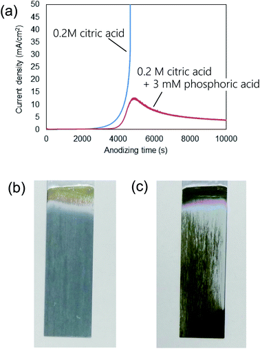
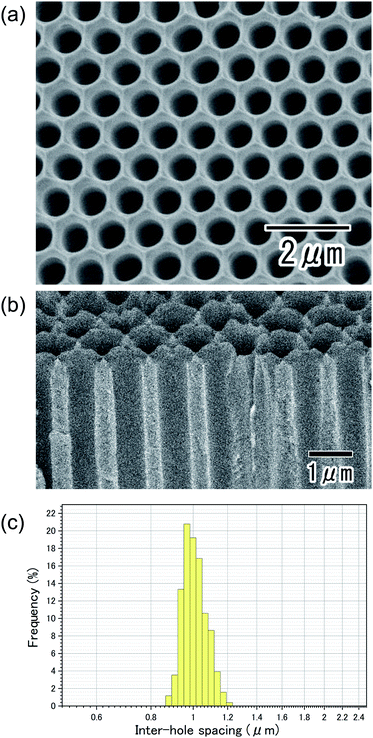
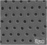
Fig. 1(a) shows the current–time curves obtained during the anodization of an Al sheet at a constant voltage of 400 V in 0.2 M citric acid electrolyte with and without 3 mM phosphoric acid. In Fig. 1(a), a leading time for the current flow was observed in both electrolytes. Although the reason for the appearance of this leading time in the current flow is not clear at the present stage, it is thought that the leading time corresponds to the dissolution of the native insulating oxide layer on the surface of Al. In the case of the anodization in 0.2 M citric acid electrolyte without phosphoric acid, a steep increase in the current density occurred and caused burning after 4000 s. On the other hand, stable anodization was achieved in the electrolyte containing a small amount of phosphoric acid. Fig. 1(b and c) show photographs of samples obtained in 0.2 M citric acid electrolytes with and without 3 mM phosphoric acid, respectively. The sample obtained in a 0.2 M citric acid electrolyte with 3 mM phosphoric acid was uniformly gray. This means that the thickness of the oxide layer was almost uniform all over the sample. On the other hand, the appearance of the sample obtained without phosphoric acid was nonuniformly gray and brown, and considerable unevenness in the film thickness was also observed. In addition, a black part corresponding to the burning was observed on the edge part of the sample.Fig. 2 shows (a) surface and (b) cross-sectional SEM images of a typical ordered anodic porous alumina obtained by anodization at 400 V. For this sample, anodization was carried out in 0.2 M citric acid electrolyte containing 3 mM phosphoric acid for 48 h. From the SEM images shown in Fig. 2(a and b), it can be observed that uniform-sized holes were hexagonally arranged over the sample. Fig. 2(c) shows the inter-hole spacing distribution of the obtained sample. The average inter-hole spacing measured from SEM images was 1.0 μm, which is in good agreement with the existing ratio of the inter-hole spacing to the applied voltage (2.5 nm V−1). There has been a report on the preparation of ordered porous alumina with an inter-hole spacing of ca. 900 nm.29 However, the anodizing condition was very harsh, and there was a limit to increasing the sample area. On the other hand, the anodizing condition reported here is relatively mild, so it can be expected to be applied to large-sample preparation.
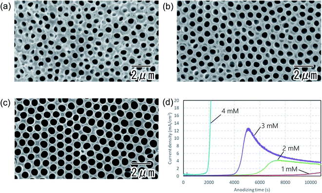
Fig. 3 shows the dependence of the degree of ordering in the hole arrangement on the concentration of phosphoric acid. The first anodization was carried out in a 0.2 M citric acid electrolyte containing 1 (a), 2 (b), and 3 mM (c) phosphoric acid. In all cases, the thickness of the first oxide layer was adjusted to 50 μm by changing the anodization time. In Fig. 3, the degree of ordering in the hole arrangement increased with the concentration of phosphoric acid. Fig. 3(d) shows current–time transients during anodization for different concentrations of phosphoric acid mixed with citric acid. In the case of the excess addition of phosphoric acid above 3 mM, stable anodization was difficult because of the outbreak of burning. Although the detailed mechanism behind the improvement of the degree of ordering of the hole arrangement upon the addition of a small amount of phosphoric acid for is not clear at present, it is thought that the high dissolution rate at a high concentration of phosphoric acid contributes to the higher ordering. This result indicates that a small change in the concentration of phosphoric acid significantly affects the degree of ordering of the hole arrangement.
Fig. 4 shows the dependence of the degree of ordering in the hole arrangement on the time for anodization. The samples were anodized at a constant voltage of 400 V in a 0.2 M citric acid electrolyte containing 3 mM phosphoric acid. The anodization times were 3 (a), 12 (b), and 48 h (c). The SEM images in Fig. 4 show that the degree of ordering in the hole arrangement increased with the time of anodization. This result indicates that the increase in the degree of ordering proceeds with the growth of the oxide layer under appropriate anodizing conditions.
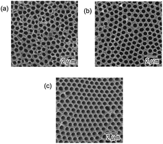 | ||
| Fig. 4 Dependence of degree of ordering in the hole arrangement on the time for anodization. The first anodization times were 3 (a), 12 (b), and 148 h (c). | ||
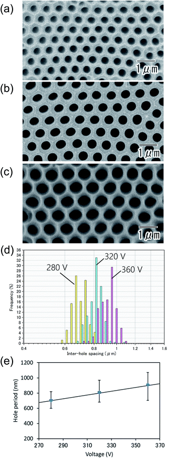
Fig. 5(a–c) show the SEM images of the anodic porous alumina prepared at different applied voltages: 280 (a), 320 (b), and 360 V (c). In all samples, highly ordered hole arrangement was confirmed. From inter-hole spacing shown in Fig. 5(d), the average inter-hole spacings of the samples prepared at 280, 320, and 360 V were found to be 710, 810, and 910 nm, respectively. In Fig. 5(e), the relationship between the inter-hole spacings and applied voltages is summarized. The average inter-hole spacings showed a good linear relationship with the applied voltage, where the ratio of the inter-hole spacing to anodization voltages is 2.5 nm V−1.
To successfully prepare the ordered anodic porous alumina with larger inter-hole spacings and hole sizes, exploration of the appropriate anodizing conditions at higher applied voltage is required. Fig. 6 shows the surface SEM image of the ordered anodic porous alumina obtained at 600 V. For this sample, an electrolyte with a mixture of water and ethylene glycol (1![[thin space (1/6-em)]](https://www.rsc.org/images/entities/char_2009.gif) :
:![[thin space (1/6-em)]](https://www.rsc.org/images/entities/char_2009.gif) 1 volume ratio) containing citric acid and phosphoric acid were used for the anodization. In the case of anodization in a citric acid electrolyte containing phosphoric acid at appropriate applied voltages of over 400 V, stable anodization was difficult because of sample damage due to the break down of oxide film. It has been reported that the addition of an appropriate organic solvent, such as ethylene glycols, can suppress the break down, allowing stable anodization at high applied voltages.24,25 In the case of the sample shown in Fig. 6, the hole arrangement of the sample was observed from the bottom of the oxide layer after removing Al and the subsequent through-holing, because it was difficult to perform the two-step anodization at a high voltage of over 400 V. The etching of Al was carried out in a saturated iodine methanol solution at 50 °C. The through-holing of the sample was carried out using an Ar ion milling apparatus. From the SEM image shown in Fig. 6, it was observed that uniform-size holes are in an orderly arrangement all over the entire sample. The average inter-hole spacing of the obtained sample was 1.5 μm. The ratio of the inter-hole spacing against the applied voltages was also 2.5 nm V−1. This means that the ratio of the inter-hole spacing to the applied voltage holds even in the case of anodization in the electrolyte with a mixture of water and ethylene glycol.
1 volume ratio) containing citric acid and phosphoric acid were used for the anodization. In the case of anodization in a citric acid electrolyte containing phosphoric acid at appropriate applied voltages of over 400 V, stable anodization was difficult because of sample damage due to the break down of oxide film. It has been reported that the addition of an appropriate organic solvent, such as ethylene glycols, can suppress the break down, allowing stable anodization at high applied voltages.24,25 In the case of the sample shown in Fig. 6, the hole arrangement of the sample was observed from the bottom of the oxide layer after removing Al and the subsequent through-holing, because it was difficult to perform the two-step anodization at a high voltage of over 400 V. The etching of Al was carried out in a saturated iodine methanol solution at 50 °C. The through-holing of the sample was carried out using an Ar ion milling apparatus. From the SEM image shown in Fig. 6, it was observed that uniform-size holes are in an orderly arrangement all over the entire sample. The average inter-hole spacing of the obtained sample was 1.5 μm. The ratio of the inter-hole spacing against the applied voltages was also 2.5 nm V−1. This means that the ratio of the inter-hole spacing to the applied voltage holds even in the case of anodization in the electrolyte with a mixture of water and ethylene glycol.
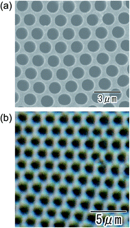
Fig. 7 shows the SEM (a) and optical microscopy (b) images of the ordered anodic porous alumina obtained at 700 V. Anodization was carried out in an electrolyte with a mixture of water and tetraethylene glycol (1![[thin space (1/6-em)]](https://www.rsc.org/images/entities/char_2009.gif) :
:![[thin space (1/6-em)]](https://www.rsc.org/images/entities/char_2009.gif) 1 in volume). We found that the use of tetraethylene glycol was effective for stable anodization at higher applied voltage. From the SEM image shown in Fig. 7(a), it can be confirmed that uniform-sized holes are in an orderly arrangement over the sample. From the optical microscopy image in Fig. 7(b), it was also confirmed that uniformly sized holes were arranged orderly over the sample. It is noteworthy that the geometrical structures of the anodic porous alumina can be observed even under an optical microscope. This will contribute to the expansion of the range of application of ordered anodic porous alumina. The average inter-hole spacing in the sample was 1.8 μm. This value of the inter-hole spacings is the largest for naturally occurring highly ordered porous alumina ever reported. There have been several reports on preparing highly ordered anodic porous alumina with large inter-hole spacing.30–32 However, it was not easy to obtain the highly ordered anodic porous alumina with an inter-hole spacing over 800 nm under those anodizing conditions. The preparation of anodic porous alumina with inter-hole spacings of 1400–2036 nm has also been reported so for.25 However, the ordering degree of the hole arrangement was not satisfactory. The anodizing conditions reported here can produce the highly ordered anodic porous alumina with inter-hole spacings of 710 nm to 1.8 μm successfully.
1 in volume). We found that the use of tetraethylene glycol was effective for stable anodization at higher applied voltage. From the SEM image shown in Fig. 7(a), it can be confirmed that uniform-sized holes are in an orderly arrangement over the sample. From the optical microscopy image in Fig. 7(b), it was also confirmed that uniformly sized holes were arranged orderly over the sample. It is noteworthy that the geometrical structures of the anodic porous alumina can be observed even under an optical microscope. This will contribute to the expansion of the range of application of ordered anodic porous alumina. The average inter-hole spacing in the sample was 1.8 μm. This value of the inter-hole spacings is the largest for naturally occurring highly ordered porous alumina ever reported. There have been several reports on preparing highly ordered anodic porous alumina with large inter-hole spacing.30–32 However, it was not easy to obtain the highly ordered anodic porous alumina with an inter-hole spacing over 800 nm under those anodizing conditions. The preparation of anodic porous alumina with inter-hole spacings of 1400–2036 nm has also been reported so for.25 However, the ordering degree of the hole arrangement was not satisfactory. The anodizing conditions reported here can produce the highly ordered anodic porous alumina with inter-hole spacings of 710 nm to 1.8 μm successfully.
Conclusions
Self-ordered anodic porous alumina with long-range ordered hole arrangement having inter-hole spacings of over 1.5 μm could be obtained by anodization using a citric acid electrolyte containing a small amount of phosphoric acid. It was confirmed that the degree of ordering in hole arrangement depends on the conditions of anodization. Additionally, the use of an electrolyte with a mixture of water and ethylene glycols, particularly tetraethylene glycol, was effective for the formation of long-range ordered anodic porous alumina with large inter-hole spacings of up to 1.8 μm. The ordered anodic porous alumina obtained in the present study is expected to be applied in various functional devices that require ordered hole arrangements with large inter-hole spacings and hole sizes.Conflicts of interest
There are no conflicts to declare.References
- H. Li, M. Eddaoudi, M. O'Keeffe and O. M. Yaghi, Nature, 1999, 402, 276 CrossRef CAS
.
- M. E. Davis, Nature, 2002, 417, 813 CrossRef CAS
.
- M. R. Jones, K. D. Osberg, R. J. Macfarlane, M. R. Langille and C. A. Mirkin, Chem. Rev., 2011, 111, 3736 CrossRef CAS
.
- A. G. Cullis, L. T. Canham and P. D. J. Calcott, J. Appl. Phys., 1997, 82, 909 CrossRef CAS
.
- Y. Wan and D. Zhao, Chem. Rev., 2007, 107, 2821 CrossRef CAS
.
- G. E. Boyd, A. W. Adamson and L. S. Myers Jr, J. Am. Chem. Soc., 1947, 69, 2836 CrossRef CAS
.
- C. A. Huber, T. E. Huber, M. Sadoqi, J. A. Lubin, S. Manalis and C. B. Prater, Science, 1994, 263, 800 CrossRef CAS
.
- S. H. Jeong, H. Y. Hwang, K. H. Lee and Y. Jeong, Appl. Phys. Lett., 2001, 78, 2052 CrossRef CAS
.
- A. Kolmakov, Y. Zhang, G. Cheng and M. Moskovits, Adv. Mater., 2003, 15, 997 CrossRef CAS
.
- E. M. I. M. Ekanayake, D. M. G. Preethichandra and K. Kaneto, Biosens. Bioelectron., 2007, 23, 107 CrossRef CAS
.
- Y. Cao and T. T. E. Mallouk, Chem. Mater., 2008, 20, 5260 CrossRef CAS
.
- S. D. Alvarez, C. Li, C. E. Chiang, I. K. Schuller and M. J. Sailor, ACS Nano, 2009, 3, 3301 CrossRef CAS
.
- F. Keller, M. S. Hunter and D. L. Robinson, J. Electrochem. Soc., 1953, 100, 411 CrossRef CAS
.
- H. Masuda, T. Yanagishita and T. Kondo, Encyclopedia of Interfacial Chemistry: Surface Science and Electrochemistry, Elsevier, 2018, p. 226 Search PubMed
.
- H. Masuda, K. Takenaka, T. Ishii and K. Nishio, Jpn. J. Appl. Phys., 2006, 45, L1165 CrossRef CAS
.
- H. Masuda, M. Nagae, T. Morikawa and K. Nishio, Jpn. J. Appl. Phys., 2006, 45, L406 CrossRef CAS
.
- H. Masuda, H. Hasegawa and S. Ono, J. Electrochem. Soc., 1997, 144, L127 CrossRef CAS
.
- H. Masuda and K. Fukuda, Science, 1995, 268, 146 CrossRef
.
- H. Masuda, K. Yada and A. Osaka, Jpn. J. Appl. Phys., 1998, 37, L1340 CrossRef
.
- A. Escosura-Muniz, W. Chunglok, W. Surareungchai and A. Merkoci, Biosens. Bioelectron., 2013, 40, 24 CrossRef
.
- M. Enfrin, J. Lee, P. Le-Clech and L. F. Dumée, J. Membr. Sci., 2020, 1, 117890 CrossRef
.
- L. Zhang, B. Majeed, L. Lagae, P. Peumans, C. V. Hoof and W. D. Malsche, J. Chromatogr. A, 2013, 1294, 1 CrossRef CAS
.
- S. Z. Chu, K. Wada, S. Inoue, M. Isogai, Y. Katsuta and A. Yasumori, J. Electrochem. Soc., 2006, 153, B384 CrossRef CAS
.
- Q. Wang, Y. Long and B. Sun, J. Porous Mater., 2013, 20, 785 CrossRef CAS
.
- X. Chen, D. Yu, L. Cao, X. Zhu, Y. Song, H. Huang, L. Lu and X. Chen, Mater. Res. Bull., 2014, 57, 116 CrossRef CAS
.
- J. Bellemare, F. Siroois and D. Menard, J. Electrochem. Soc., 2014, 161, E75 CrossRef CAS
.
- Y. Li, N. Peng, W. Shang, Y. Wen and Y. He, J. Electrochem. Soc., 2020, 167, 021508 CrossRef CAS
.
- H. Masuda and M. Satoh, Jpn. J. Appl. Phys., 1996, 35, L126 CrossRef CAS
.
- Y. Ma, Y. Wen, J. Li, Y. Li, Z. Zhang, C. Feng and R. Sun, Sci. Rep., 2016, 6, 39165 CrossRef CAS
.
- X. Qin, J. Zhang, X. Meng, C. Deng, L. Zhang, G. Ding, H. Zeng and Z. Xu, Appl. Surf. Sci., 2015, 328, 459 CrossRef CAS
.
- A. Takenaga, T. Kikuchi, S. Natsui and R. O. Suzuki, Electrochim. Acta, 2016, 211, 515 CrossRef CAS
.
- M. Norek and M. Wlodarski, J. Porous Mater., 2018, 25, 45 CrossRef CAS
.
| This journal is © The Royal Society of Chemistry 2021 |

