 Open Access Article
From an Fe2P3 complex to FeP nanoparticles as efficient electrocatalysts for water-splitting†
Shenglai
Yao‡
 a,
Viktoria
Forstner‡
a,
Prashanth W.
Menezes‡
a,
Viktoria
Forstner‡
a,
Prashanth W.
Menezes‡
 a,
Chakadola
Panda‡
 a,
Stefan
Mebs
b,
Eva M.
Zolnhofer
c,
Matthias E.
Miehlich
c,
Tibor
Szilvási
d,
Nanjundan
Ashok Kumar
 e,
Michael
Haumann
b,
Karsten
Meyer
 *c,
Hansjörg
Grützmacher
 *f and
Matthias
Driess
 *a
*a
aDepartment of Chemistry: Metalorganics and Inorganic Materials, Technische Universität Berlin, Strasse des 17. Juni 135, Sekr. C2, D-10623 Berlin, Germany. E-mail: matthias.driess@tu-berlin.de
bDepartment of Physics, Freie Universität Berlin, Arnimallee 14, D-14195 Berlin, Germany
cDepartment of Chemistry and Pharmacy, Friedrich-Alexander-University Erlangen-Nürnberg (FAU), Egerlandstrasse 1, 91058 Erlangen, Germany. E-mail: karsten.meyer@fau.de
dDepartment of Chemical & Biological Engineering, University of Wisconsin—Madison, 1415 Engineering Drive, 53706, Madison, WI, USA
eSchool of Chemical Engineering, The University of Queensland, St Lucia, Brisbane, 4072, Australia
fDepartment of Chemistry and Applied Biosciences, ETH Zürich, Vladimir-Prelog Weg 1, Hönggerberg, CH-8093, Zürich, Switzerland. E-mail: hgruetzmacher@ethz.ch
First published on 17th September 2018
Abstract
In large-scale, hydrogen production from water-splitting represents the most promising solution for a clean, recyclable, and low-cost energy source. The realization of viable technological solutions requires suitable efficient electrochemical catalysts with low overpotentials and long-term stability for both hydrogen evolution reaction (HER) and oxygen evolution reaction (OER) based on cheap and nontoxic materials. Herein, we present a unique molecular approach to monodispersed, ultra-small, and superiorly active iron phosphide (FeP) electrocatalysts for bifunctional OER, HER, and overall water-splitting. They result from transformation of a molecular iron phosphide precursor, containing a [Fe2P3] core with mixed-valence FeIIFeIII sites bridged by an asymmetric cyclo-P(2+1)3− ligand. The as-synthesized FeP nanoparticles act as long-lasting electrocatalysts for OER and HER with low overpotential and high current densities that render them one of the best-performing electrocatalysts hitherto known. The fabricated alkaline electrolyzer delivered low cell voltage with durability over weeks, representing an attractive catalyst for large-scale water-splitting technologies.
Introduction
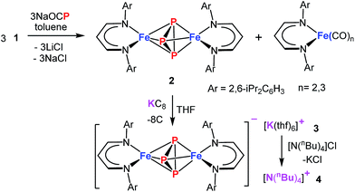
The demand for a clean, recyclable, and low-cost energy source has never been greater in this modern civilization. Hydrogen generated from water-splitting using carbon-neutral solar energy represents the most promising and attractive solution to meet the future global demand.1 During the last decade, significant progress has been made in developing efficient electrochemical catalysts for water-splitting reactions.2–5 However, to increase the efficiency of water electrolysis it is highly desirable to reduce the large overpotentials for both half reactions – hydrogen evolution reaction (HER) and oxygen evolution reaction (OER). Although numerous catalysts for either OER (e.g., oxides,6 hydroxides,6 perovskites,7,8 nitrides,9 borides,10 chalcogenides11,12 and phosphates13) or HER (e.g. nitrides,14 chalcogenides,11,15 borides,10 carbides16 and phosphides17) have been developed, currently, the most effective state-of-the-art catalysts for electrolysis of water contain noble metals, such as platinum, iridium, and ruthenium, which are expensive and scarce.18,19 This defines a central scientific goal in this area.6 The development of cheaper bifunctional HER and OER electrocatalysts with enhanced catalytic activity and long-term stability in a common electrolyte still remains a challenge.20 Most of the unifunctional catalysts deliver lower efficiency for overall water-splitting when paired as anode and cathode in the same electrolyte.21,22 In this regard, various materials based on first-row transition-metals have been explored for bifunctional OER and HER, and show promising catalytic properties when the oxidized and reduced form possess adaptable redox properties.12,23,24Among the most promising classes of compounds containing non-precious metals, the phosphides of iron, cobalt, and nickel have gained particular interest in the last couple of years.11,17,24–27 They exhibit remarkable catalytic performances both for OER and HER because of their particular electronic structures as a result of redox-active metal and phosphorous sites with variable metal-to-phosphorus ratios.24,26–28 However, the synthesis of such phosphides usually involves high pressure and high temperature solid-state or solid–gas reactions that lead to a random distribution of relatively large particles with low catalytic activity.26,28 An alternate approach, that processes a single source molecular precursor (containing both M and P) in to multi-functional inorganic material (MPx), in solution/gas phase is highly promising because atomic level control over the stoichiometry, nanostructure, elemental dispersion, and surface structure in the final solid can be predictably enforced.29,30 Generally this approach enables the preparation of small nano-sized particles with narrow size distribution and high homogeneity. Moreover, the preexistence of M–P bonds would significantly lower the activation barrier such that syntheses can be achieved at relatively low temperature. Although a few molecular approaches to produce metal phosphides are known,31,32 using a single source molecular precursor, containing all the desired elements (e.g. both M and P) is rare.33 Schaidle and co-workers have reported on making various mono dispersed transition metal phosphides starting from triphenyl phosphine coordinated metal complexes where the phosphine served as the source of P in the final solid.33 We envisioned for the preparation of a suitable molecular precursor with isolated Pn cluster directly linked to the metal center for the synthesis of small FenPm nanoparticles at low temperature. Potentially suitable precursors for metal phosphides, including iron, are molecular polyphosphide complexes, which have been prepared from white phosphorus (P4) as a phosphorous source.34–37 Recently, the phosphaethynolate (OCP)− anion has emerged as a masked anionic phosphorus transfer reagent for the preparation of p-, d-, and f-block metal compounds.38–44 Herein, we report the reaction of Na(OCP) with the chlorido-β-diketiminato iron(II) complex 1, which furnishes the diiron triphosphide complex 2, featuring a mixed-valence FeIIP3FeIII core and asymmetric cyclo-P(2+1) ligand (Scheme 1). In fact, 2 serves as a low-temperature precursor for monodisperse ultra-small FeP nanoparticles that act as long-lasting bifunctional electrocatalysts for water-splitting with low overpotentials and high current densities representing them one of the versatile electrocatalysts for the future energy conversion.
Results and discussion
Synthesis and characterisation of a molecular triphosphido diiron precursor
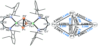
Treatment of Na(OCP) with chlorido-β-diketiminato iron–lithium complex [LHFeCl2Li(thf)2] 1 (ref. 36) (LH = CH(CHNDipp)2, Dipp = 2,6-iPr2C6H3) at room temperature leads to [(LHFe)2(μ-η3:η3-P3)] 2 in 52% yield, along with [LHFe(CO)3] and [LHFe(CO)2]45 (Scheme 1). Compound 2 has been isolated and fully characterized, including high-resolution ESI-mass spectrometry, 1H-NMR spectroscopy, and single-crystal X-ray crystallography.It crystallizes in the monoclinic space group C2/c (Fig. 1) and contains an Fe2P3 core with a distorted trigonal-bipyramidal geometry. The cyclo-P3 ligand is equally disordered over two orientations that are related to each other by an inversion centre. Notably, the P–P distances in 2 are different: the P1–P2′ bond of 2.193(2) Å is significantly shorter than the other two (P1–P3′ 2.310(2) Å and P2′–P3′ 2.299(2) Å). The former is very close to the P–P bond distances found in [Fe2(μ-η4:η4-P4)] (2.178(1)–2.207(1) Å) and the latter two are longer than those in [Fe4(μ4-η2:η2:η2:η2-P8)] (2.1991(8)–2.2813(7) Å) supported by β-diketiminato ligands.37 Cyclo-P3 iron complexes are rare and, to the best of our knowledge, only two examples have been described: [(Cp*Fe)3{(η3-P3)Fe}P6] (Cp* = C5(Me)5)46 and the bimetallic triple-decker complex [{(triphos)Co}(μ,η3:3-cyclo-P3){Fe(triphos)}](PF6)2 with the tripodal triphosphine ligands MeC-(CH2PPh2)3 and MeC(CH2PEt2)3.47
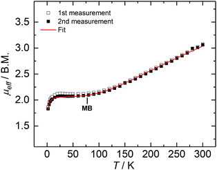
Complex 2 is paramagnetic in solution, as shown by 1H NMR spectroscopy (Fig. S1†). The effective magnetic moment (μeff) of a microcrystalline solid sample, measured with a SQUID magnetometer, is temperature-dependent (Fig. 2), and determined to be 3.07 Bohr magneton (μB) at 300 K. The magnetic moment continuously decreases with decreasing temperature, plateaus at approx. 80 K with a value of 2.12 μB, and further decreases below 20 K to reach 1.86 μB at 2 K; thus, revealing a doublet electronic ground state for 2 at low temperatures. This ground state is the result of an antiferromagnetically coupled, mixed-valence FeII/FeIII high-spin system, in which the magnetic exchange coupling constant (J) has been determined to be −110 cm−1 (in the exchange Hamiltonian −2JS1S2 with S1 = 2.5, and S2 = 2.0).
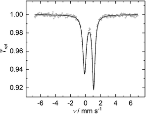
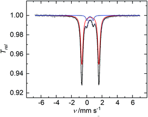
The CW X-band EPR spectrum, recorded in frozen toluene solutions at 7 K, shows a rhombic signal with effective g-values cantered at g1 = 2.17, g2 = 2.07, g3 = 1.98, and hyperfine coupling to three equivalent 31P nuclei (A(31P) with nuclear spin I = 1/2, 100% nat. abundance: A1 = 51.3, A2 = 77.9, A3 = 56.4 MHz) (Fig. 3), supporting the Stot = 1/2 ground state, in line with the SQUID magnetization data. Moreover, the zero-field 57Fe Mössbauer spectrum of 2, recorded on a solid sample at 77 K, exhibits a single, asymmetric quadrupole doublet with an isomer shift (δ) of 0.48(1) mm s−1 and a quadrupole splitting (ΔEQ) of 1.29(1) mm s−1 (Fig. 4). This indicates that the valence states and electronic structures of the two iron sites in 2 are identical on the time scale of the Mössbauer measurement (ca. 10−7 s) at 77 K; ultimately suggesting a delocalized, mixed-valence FeIIFeIII system with a bridging [P3]3− ligand. Related FeIIFeIII complexes with ((μ-η2:η2-P2)2)4− and (μ-S)24− ligands and delocalized electronic structures were reported by us recently.36,48
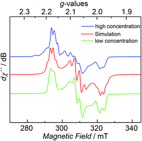 | ||
| Fig. 3 CW X-band EPR spectrum of 2 at 7 K with different concentrations (blue and green trace), and its simulation (red trace), see ESI† for details. | ||
The cyclic voltammogram of 2 shows several features (Fig. S6†), of which the reversible redox-wave centered at E1/2 = −1.74 V (vs. Fc/Fc+) is attributed to the one-electron redox event FeIIIFeII/FeIIFeII. Synthetically, reduction of 2 with KC8 affords 3 in 86% yields as dark green crystals (Scheme 1). Complex 3 crystallized as separated ion pair and the molecular structure of the anion in crystals of [3]·THF is very similar to that of 2 discussed above (Fig. S5†). The 57Fe Mössbauer spectrum of a solid sample of 3, recorded at 77 K in zero-field, displays a doublet with an isomer shift of 0.50(1) mm s−1 and a quadrupole splitting of 2.28(1) mm s−1 (Fig. S10b†), indicating the presence of only high-spin FeII sites. The presence of impurities of 2 in the sample could not be avoided; presumably, due to the high sensibility of 3, which is easily oxidized back to 2. In order to purify 3, cation exchange using nBu4NCl led to the formation of 4 as dark green crystals, isolated in 60% yields (Scheme 1). The 57Fe Mössbauer spectrum exhibits a doublet for 4 (δ = 0.48(1) mm s−1, ΔEQ = 2.24(1) mm s−1), within the error margin alike to 3 (Fig. 5). The nearly unchanged isomer shifts in 2 and 3/4 indicate that the unpaired electron in 2 mostly resides on the bridging P3 moiety.
To further characterize the electronic structures of 2 and 3, X-ray absorption spectroscopy (XAS) was employed on powders of 2 and 3 (Fig. S12–S14†). EXAFS (Extended X-ray Absorption Fine Structure) measurements at the Fe K-edge at 20 K reveal overall similar bond lengths in 2 and 3 compared to those obtained from single crystal XRD analysis. The XANES (X-ray Absorption Near Edge Structure) study reveals an FeIIFeII core in 3. The negligible edge energy increase in 2 indicates that relatively few electron density is abstracted from the iron centres upon oxidation of 3, suggesting a merely ligand-centred oxidation, as confirmed by Density Functional Theory calculations (Fig. S14–S19 and Tables S6–S10†), and in agreement with the Mössbauer isomer shifts (δ (2) = 0.48(1), δ (3) = 0.50(1) mm s−1, δ (4) = 0.48(1) mm s−1).
DFT-optimized structures of 2 and 3 reveal similar overall bond lengths as found by crystallography and EXAFS. While the iron sites in symmetric 3 are almost equal, significant bond length differences are seen at the formal FeIII and FeII centres in the asymmetric complex 2. The X-ray pre-edge absorption differences in 2vs.3 were satisfactorily reproduced by TDDFT calculations on the geometry-optimized structures, showing that the electronic structures are adequately modelled with TPSSh/TZVP theory. Thus, the pre-edge features could be attributed to underlying electronic excitations, which show that the spectral differences in 2vs.3 are mainly due to changes of transition energies and oscillator strengths, in response to the bond lengths change, at the formal FeIII centre in 2.
Unrestricted Hartree–Fock corresponding orbitals (UCO), spin density (SD), charge (QCM5), Mayer bond order (MBO), atoms-in-molecules (AIM), and non-covalent interactions indicator (NCI) analyses provide a detailed picture of the spin and charge distribution and bonding interactions in the compounds. The analysis reveals that the oxidation of 3 is a ligand-centered process but some charge redistribution at the iron centres and one more positively charged (formally FeIII) ion is observed in 2. Remarkably, an asymmetric P1+2 ligation model is preferred over a symmetric P3 ligation model in both, 2 and 3, and spin polarisation and significant spin density at the special P atom is seen in 2. Considerable electron delocalization around the [FeP3Fe]-core is observed in both complexes and stabilization of the structures by additional non-covalent interactions. Altogether, the data suggest that 3 is a symmetric FeIIFeII complex, but 2, in agreement with the magnetization study (vide supra), corresponds to an asymmetric FeIIIFeII complex with antiferromagnetic coupling of the iron ions to yield a total spin Stot = 1/2 system (likely prevailing under the XAS conditions at 20 K).
Synthesis, characterization, and catalytic reactivity of FeP electrocatalyst
Encouraged by our previous results on iron chalcogenides,12 we investigated the suitability of 2 to act as a low-temperature molecular precursor to form a nano-sized iron phosphide particle electrocatalyst. Accordingly, we transformed 2 under hot injection conditions in oleylamine (CH3(CH2)7CH![[double bond, length as m-dash]](https://www.rsc.org/images/entities/char_e001.gif) CH(CH2)7CH2NH2) to attain iron phosphide (FeP) materials. Although several phases exist in the phase diagram of iron phosphide (Fe3P, Fe2P, FeP2, and FeP), we anticipated that the thermolytic cleavage of 2 furnishes thermodynamically preferred FeP nanoparticles due to the favorable cohesive energy and formation enthalpy of FeP within the Fe–P phase diagram.49 The latter consists of a crystalline phase as shown by powder X-ray diffraction (PXRD) analysis (Fig. S20†) and broad reflections indicate the presence of small nanocrystallites.
CH(CH2)7CH2NH2) to attain iron phosphide (FeP) materials. Although several phases exist in the phase diagram of iron phosphide (Fe3P, Fe2P, FeP2, and FeP), we anticipated that the thermolytic cleavage of 2 furnishes thermodynamically preferred FeP nanoparticles due to the favorable cohesive energy and formation enthalpy of FeP within the Fe–P phase diagram.49 The latter consists of a crystalline phase as shown by powder X-ray diffraction (PXRD) analysis (Fig. S20†) and broad reflections indicate the presence of small nanocrystallites.
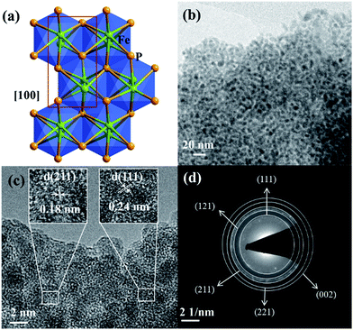
The as-synthesized FeP crystallizes in the orthorhombic space group Pna21 and the crystal packing along [100] is shown (Fig. 6a).50 The transmission electron microscopy (TEM) and high-resolution (HR) TEM revealed homogenously distributed nanoparticles of 2–5 nm in size and the corresponding lattice spacing (JCPDS 71-2262) and characteristic rings evidencing the phase-purity of FeP (Fig. 6b–d and S22†). The chemical composition was confirmed by means of energy dispersive X-ray (EDX) analysis, inductively coupled plasma atomic emission spectroscopy (ICP-AES), and X-ray photoelectron spectroscopy (XPS) (Fig. S23 and Table S11†). In addition, SEM image and EDX mapping performed on the FeP nanoparticles displayed the homogenous distribution of iron and phosphorous (Fig. S21†). The XPS spectra of Fe 2p and P 2p matched perfectly with the literature-reported examples of FeP (Fig. S24†).
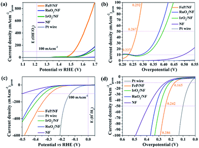
The as-synthesized FeP was deposited electrophoretically on a 3D porous and conductive nickel foam (NF) substrate that directly served as anode or cathode. The catalytic OER and HER were measured in alkaline 1 M KOH solution. Fig. 7a shows the linear sweep voltammogram (LSV) of FeP for OER at a sweep rate of 1 mV s−1. At a current density of 10 mA (cm)−2 (Fig. 7b), an overpotential of 227 mV is obtained for FeP that is exceptionally lower in comparison to commercial noble metal-based catalysts (IrO2, RuO2, Pt) (Table S12†). While cycling between 1.2 to 1.4 V (vs. RHE), a reversible redox event, corresponding to Fe(OH)2 + OH− → FeOOH + H2O + e− centered at 1.34 V was observed; thus, suggesting surface oxidation of Fe to a higher valence state. This observation has been well-documented for Fe-based OER catalysts (Fig. S25†).
To examine the kinetics of OER, Tafel plots were drawn and the Tafel slope was determined to be 54 mV dec−1. This is significantly smaller compared to noble-based (RuO2 and IrO2) catalysts, implying fast reaction kinetics of FeP (Fig. S26†). The obtained Tafel slope value of 54 mV dec−1 indicates that the first adsorption of H2O followed by a proton-coupled electron transfer steps to form a Fe–OHads on the surface could be the rate-determining step to furnish a O–O bond.51,52 The electrochemical active surface area (ECSA) of FeP was evaluated from electrochemical double-layer capacitance (Cdl) and the calculated Cdl was 1.01 mF cm−2.53,54 The Cdl was converted into ECSA using the specific capacitance of the material per unit area, and a value of 0.6 cm2 was estimated that provides information on the catalytic active sites favoring the efficient adsorption and transfer of reactants to enhance the electrochemical reaction.55 The electrochemical impedance spectroscopy (EIS) was performed to examine the electron transfer ability of FeP. As shown in the Nyquist plot (Fig. S28c and d†), the FeP possesses a much smaller semicircle that confirms the superior electron conductivity. In analogy to OER catalysis, we have also examined the HER activity (Fig. 7c). An overpotential of 166 mV at a current density of −10 mA (cm)−2 was measured, which is lower than those obtained for many other noble-based catalysts, although slightly higher than that of a Pt wire (Fig. 7d; Table S13†). A Tafel slope of 97 mV (dec)−1 was acquired for HER (Fig. S29†). Overall, the OER and HER overpotentials acquired with nanocrystalline FeP from 2 are among the lowest values in comparison to best-performing OER and HER catalysts (Tables S12 and S13†). Apart from the high catalytic activity, remarkable long-term chronoamperometric stabilities were also assessed at a potential of 1.46 and −0.16 V (vs. RHE) over 15 h for OER and HER, respectively (Fig. S27 and S30†).
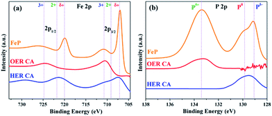
To reveal the active structures of the FeP material during each half reaction of OER and HER, the catalysts were further examined by post operando microscopic and spectroscopic techniques. Under OER conditions, the TEM and HER-TEM images showed destruction of FeP particles with formation of amorphous material under electrochemical and strongly alkaline conditions, which could be attributed to the loss of a large amount of phosphorus (as detected from ICP-AES and EDX) and simultaneous oxidation of Fe starting from the surface of the FeP particles forming Fe(OH)2/FeOOH phases with defects and disorders (Fig. S25, S31 and S33†). This phenomenon has been previously described in the literature for first-row transition metal-based materials investigated for OER catalysis.12 Regardless, the core of the particle retained its crystallinity with respective lattice planes and a weakly diffracted SAED revealed rings corresponding to FeP. On the contrary to OER, under HER conditions, FeP was found to be purely crystalline with clear lattice spacing and rings as observed in TEM, HR-TEM, and SAED, without losing significant amounts of phosphorous from the surface under strongly alkaline conditions (Fig. S32†). The ICP-AES analysis confirmed loss of P during OER of ∼45%, whereas only ∼3% of P was lost during HER. However, the leaching of Fe in both OER and HER was negligible (<1%). The surface of the thin films during OER was analyzed by high-resolution XPS. During OER conditions, the Fe 2p3/2 peak at 707 eV and Fe 2p1/2 peak at 719.9 eV – corresponding to the Feδ+ (of as-synthesized FeP) – disappeared, forming broad new peaks at 710.7 and 724.9 eV that can be ascribed to the existence of Fe3+. Except for two new shoulders at 710 (2p3/2) and 721.5 eV (2p1/2), which can be attributed to Fe2+ due to surface oxidation in strongly alkaline conditions (Fig. 8a), the XPS spectra Fe 2p almost remained unchanged under HER conditions; thus, demonstrating the stability of the Feδ+ phase. In the P 2p XPS spectra of films studied after OER, peaks responsible for Pδ−/P0 were detected at 129 and 130 eV and the peak at 133.4 eV are assigned exclusively to P5+ species, which suggests the formation of phosphates at the surface (Fig. 8b). However, no such oxidation of P occurred under HER conditions (Fig. 8). The O 1s spectra of films studied after OER displayed a broad peak, centered at 530.8 eV, that was assigned to oxygen in OH groups, indicating that the surface of the material is strongly hydroxylated. However, the material obtained under HER conditions produced a dominant peak at 529.9 eV, which is attributed to metal–oxygen bonds of FeOx (Fig. S34†). Furthermore, the Fourier transform infrared (FT-IR) spectra exhibited broad bands (∼3200 cm−1) after OER that are characteristic of hydroxyl groups, and such bands were absent in films after HER (Fig. S35†).
The superior catalytic OER performance of FeP materials can be attributed to (i) the rational design of a molecular triphosphido diiron precursor 2 to form ultra-small and monodisperse FeP nanocrystals with catalytically active surfaces, (ii) under oxidative electrochemical conditions and in strongly alkaline environments, significant amount of phosphorous leaches from the FeP nanoparticles there by forming defect-structures with anionic vacancies, and (iii) subsequent ‘corrosion’ of particles at the surface that forms an Fe-rich amorphous shell, consisting of Fe(OH)2/FeOOH species that promote the O–O bond formation to release dioxygen.
For hydrogenase and its analogues, it has been proven that the hydride acceptor has a partial positive charge, whereas the proton receptor is negatively charged, and these sites act as the vital active sites to catalyze HER.56 Therefore, we hypothesize, in FeP, the more electronegative P atoms can withdraw electron density from the Fe by acting as a base to trap protons, whereas Fe can behave as a hydride acceptor. In addition, the metallic character of FeP enhances the charge transfer from the active catalyst surface to the electrode substrate to execute efficient electrocatalytic OER and HER process.
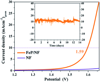
As the electrochemical results revealed superior bifunctional catalytic activities for OER and HER, we assembled an overall electrocatalytic water-splitting device in alkaline media. Notably, the FeP‖FeP on NF afforded a low cell voltage of only 1.59 V at a current density of 10 mA (cm)−2 with vigorous bubble formation at the anode and cathode (Fig. 9). One of the most attractive features of the FeP material is its unceasing durability, as manifested by chronoamperometry that demonstrated unperturbed performance over a two-week period (Fig. 9 and S36†). The evolved gases (O2 and H2) from electrolysis of water were estimated by gas chromatography and correlated to the observed current densities such that nearly 100% faradic efficiency (Table S14†) was achieved for each half-cell reaction (OER and HER). Additionally, an inverted electrochemical cell (graduated) was employed to collect the evolved H2 and O2 separately at atmospheric pressure (see ESI, Fig. S37 and S38†). The ratio of H2 evolved with respect to that of O2 was found to be 2![[thin space (1/6-em)]](https://www.rsc.org/images/entities/char_2009.gif) :
:![[thin space (1/6-em)]](https://www.rsc.org/images/entities/char_2009.gif) 1 that clearly signifies the efficient selectivity for each half-cell reactions. The electrocatalytic overall activity and durability presented here are among the best reported to date57 and demonstrate the advantage of the molecular precursor concept in designing high-performance catalysts.
1 that clearly signifies the efficient selectivity for each half-cell reactions. The electrocatalytic overall activity and durability presented here are among the best reported to date57 and demonstrate the advantage of the molecular precursor concept in designing high-performance catalysts.
Conclusions
In summary, starting from sodium phosphaethynolate and the chlorido-β-diketiminato iron(II) complex 1, the first triphosphido diiron complex [(LHFe)2(μ-η3:η3-P3)] 2, with its mixed-valence FeIIFeIII core and bridging asymmetric cyclo-P(2+1) ligand, has been synthesized and fully characterized. The molecular compound 2 proved to be a superior and convenient precursor to furnish monodispersed, ultra-small FeP nanoparticles at low temperature that show very efficient bifunctional electrochemical OER and HER and long-term stable activities in terms of overpotential and current density. Moreover, an overall water-splitting device was assembled by using the FeP electrocatalytic material as both anode and cathode that require a cell voltage of only 1.59 V to attain a current density of 10 mA (cm)−2. This study demonstrates the high potential and striking advantage of the molecular precursor concept over ‘classical’ high-temperature solid state synthesis for the design of high-performance (electro)catalysts.Author contributions
M. D., S. Y., P. W. M., K. M. and H. G. designed the research. S. Y. and V. F. performed the synthesis and characterization of compounds 2–4. C. P. and P. W. M. synthesized and characterized the electrochemical catalysts and performed the catalytic reactivity. N. A. K. performed XPS measurements. S. Y. solved the X-ray crystal structures. E. M. Z. and M. E. M. performed the Mössbauer, SQUID, and EPR measurements and analyzed the data. S. M. and M. H. performed the XAFS measurement and analyzed the EXAFS and XANES data. S. M., M. H. and T. S. performed DFT simulations. The paper was co-written by S. Y., P. W. M., C. P., M. D., M. H., K. M. and H. G. The research was supervised by M. D., K. M., and H. G. All authors discussed the results and commented on the manuscript.Conflicts of interest
There are no conflicts of interest.Acknowledgements
We are grateful to the Deutsche Forschungsgemeinschaft (Cluster of Excellence UniCat, EXC 314-2), the Swiss National Science Foundation (H. G., 2-77230-15), the Friedrich-Alexander-University Erlangen-Nürnberg (FAU), and the ETH Zürich for financial support. We also thank Dr Nils J. Lindenmaier for the cyclic voltammetry measurements, Ernesto Ballestero-Martínez for providing the NaOCP complex, and Dr Somenath Garai for solving the X-ray crystal structures. T. S. thanks for the generous support of The New Széchenyi Plan TAMOP-4.2.2/B-10/1-2010-0009. C. P. gratefully acknowledges the Alexander von Humboldt Foundation for a postdoctoral fellowship (2015–2017). M. H. thanks the BMBF for funding (Grant 05K14KE1).Notes and references
- H. B. Gray, Nat. Chem., 2009, 1, 7 CrossRef PubMed.
- D. P. Halter, F. W. Heinemann, J. Bachmann and K. Meyer, Nature, 2016, 530, 317–321 CrossRef PubMed.
- A. Singh and L. Spiccia, Coord. Chem. Rev., 2013, 257, 2419–2622 CrossRef.
- M. Huynh, C. Shi, S. J. L. Billinge and D. G. Nocera, J. Am. Chem. Soc., 2015, 137, 14887–14904 CrossRef PubMed.
- H. Liu, Y. Zhou, R. Moré, R. Müller, T. Fox and G. R. Patzke, ACS Catal., 2015, 5, 3791–3800 CrossRef.
- M. S. Burke, L. J. Enman, A. S. Batchellor, S. Zou and S. W. Boettcher, Chem. Mater., 2015, 27, 7549–7558 CrossRef.
- C. Schwanke, H. S. Stein, L. Xi, K. Sliozberg, W. Schuhmann, A. Ludwig and K. M. Lange, Sci. Rep., 2017, 7, 44192 CrossRef PubMed.
- S. Yagi, I. Yamada, H. Tsukasaki, A. Seno, M. Murakami, H. Fujii, H. Chen, N. Umezawa, H. Abe, N. Nishiyama and S. Mori, Nat. Commun., 2015, 6, 8249 CrossRef PubMed.
- C. Walter, P. W. Menezes, S. Orthmann, J. Schuch, P. Connor, B. Kaiser, M. Lerch and M. Driess, Angew. Chem., Int. Ed., 2018, 57, 698–702 CrossRef PubMed.
- H. Li, P. Wen, Q. Li, C. Dun, J. Xing, C. Lu, S. Adhikari, L. Jiang, D. L. Carroll and S. M. Geyer, Adv. Energy Mater., 2017, 7, 1700513 CrossRef.
- S. Anantharaj, S. R. Ede, K. Sakthikumar, K. Karthick, S. Mishra and S. Kundu, ACS Catal., 2016, 6, 8069–8097 CrossRef.
- C. Panda, P. W. Menezes, C. Walter, S. Yao, M. E. Miehlich, V. Gutkin, K. Meyer and M. Driess, Angew. Chem., Int. Ed., 2017, 56, 10506–10510 CrossRef PubMed.
- M. W. Kanan and D. G. Nocera, Science, 2008, 321, 1072–1075 CrossRef PubMed.
- W. F. Chen, K. Sasaki, C. Ma, A. I. Frenkel, N. Marinkovic, J. T. Muckerman, Y. Zhu and R. R. Adzic, Angew. Chem., Int. Ed., 2012, 51, 6131–6135 CrossRef PubMed.
- P. D. Tran, T. V. Tran, M. Orio, S. Torelli, Q. D. Truong, K. Nayuki, Y. Sasaki, S. Y. Chiam, R. Yi, I. Honma, J. Barber and V. Artero, Nat. Mater., 2016, 15, 640–646 CrossRef PubMed.
- Y. Liu, T. G. Kelly, J. G. Chen and W. E. Mustain, ACS Catal., 2013, 3, 1184–1194 CrossRef PubMed.
- Y. Tan, H. Wang, P. Liu, C. Cheng, F. Zhu, A. Hirata and M. Chen, Adv. Mater., 2016, 28, 2951–2955 CrossRef PubMed.
- C. C. L. McCrory, S. Jung, J. C. Peters and T. F. Jaramillo, J. Am. Chem. Soc., 2013, 135, 16977–16987 CrossRef PubMed.
- S. J. Kwon, F.-R. F. Fan and A. J. Bard, J. Am. Chem. Soc., 2010, 132, 13165–13167 CrossRef PubMed.
- P. W. Menezes, C. Panda, S. Loos, F. Bunschei-Bruns, C. Walter, M. Schwarze, X. Deng, H. Dau and M. Driess, Energy Environ. Sci., 2018, 11, 1287–1298 RSC.
- Y. Zheng, Y. Jiao, M. Jaroniec and S. Z. Qiao, Angew. Chem., Int. Ed., 2015, 54, 52–65 CrossRef PubMed.
- Y. Jiao, Y. Zheng, M. Jaroniec and S. Z. Qiao, Chem. Soc. Rev., 2015, 44, 2060–2086 RSC.
- X. Long, H. Lin, D. Zhou, Y. An and S. Yang, ACS Energy Lett., 2018, 3, 290–296 CrossRef.
- P. W. Menezes, A. Indra, C. Das, C. Walter, C. Göbel, V. Gutkin, D. Schmeißer and M. Driess, ACS Catal., 2017, 7, 103–109 CrossRef.
- A. Indra, A. Acharjya, P. W. Menezes, C. Merschjann, D. Hollmann, M. Schwarze, M. Aktas, A. Friedrich, S. Lochbrunner, A. Thomas and M. Driess, Angew. Chem., Int. Ed., 2017, 56, 1653–1657 CrossRef PubMed.
- Y. Shi and B. Zhang, Chem. Soc. Rev., 2016, 45, 1529–1541 RSC.
- Y. Wang, B. Kong, D. Zhao, H. Wang and C. Selomulya, Nano Today, 2017, 15, 26–55 CrossRef.
- J. Su, J. Zhou, L. Wang, C. Liu and Y. Chen, Sci. Bull., 2017, 62, 633–644 CrossRef.
- S. Mathur and M. Driess, in Comprehensive Organometallic Chemistry III: From Fundamentals to Applications, ed. R. H. Crabtree and D. M. P. Mingos, Elsevier, 2007, pp. 35–70 Search PubMed.
- C. Panda, P. W. Menezes and M. Driess, Angew. Chem., 2018, 130, 11298–11308 ( Angew. Chem., Int. Ed. , 2018 , 57 , 11130–11139 ) CrossRef.
- J. F. Callejas, J. M. McEnaney, C. G. Read, J. C. Crompton, A. J. Biacchi, E. J. Popczun, T. R. Gordon, N. S. Lewis and R. E. Schaak, ACS Nano, 2014, 8, 11101–11107 CrossRef PubMed.
- E. J. Popczun, J. R. McKone, C. G. Read, A. J. Biacchi, A. M. Wiltrout, N. S. Lewis and R. E. Schaak, J. Am. Chem. Soc., 2013, 135, 9267–9270 CrossRef PubMed.
- S. E. Habas, F. G. Baddour, D. A. Ruddy, C. P. Nash, J. Wang, M. Pan, J. E. Hensley and J. A. Schaidle, Chem. Mater., 2015, 27, 7580–7592 CrossRef.
- B. M. Cossairt, N. A. Piro and C. C. Cummins, Chem. Rev., 2010, 110, 4164–4177 CrossRef PubMed.
- M. Caporali, L. Gonsalvi, A. Rossin and M. Peruzzini, Chem. Rev., 2010, 110, 4178–4235 CrossRef PubMed.
- S. Yao, T. Szilvási, N. Lindenmaier, Y. Xiong, S. Inoue, M. Adelhardt, J. Sutter, K. Meyer and M. Driess, Chem. Commun., 2015, 51, 6153–6156 RSC.
- F. Spitzer, C. Graßl, G. Balázs, E. M. Zolnhofer, K. Meyer and M. Scheer, Angew. Chem., Int. Ed., 2016, 55, 4340–4344 CrossRef PubMed.
- F. F. Puschmann, D. Stein, D. Heift, C. Hendriksen, Z. A. Gal, H. F. Grützmacher and H. Grützmacher, Angew. Chem., Int. Ed., 2011, 50, 8420–8423 CrossRef PubMed.
- A. M. Tondreau, Z. Benkö, J. R. Harmer and H. Grützmacher, Chem. Sci., 2014, 5, 1545–1554 RSC.
- L. Liu, D. A. Ruiz, F. Dahcheh, G. Bertrand, R. Suter, A. M. Tondreau and H. Grützmacher, Chem. Sci., 2016, 7, 2335–2341 RSC.
- S. Yao, Y. Xiong, T. Szilvási, H. Grützmacher and M. Driess, Angew. Chem., Int. Ed., 2016, 55, 4781–4785 CrossRef PubMed.
- Y. Xiong, S. Yao, T. Szilvási, E. Ballestero-Martinez, H. Grützmacher and M. Driess, Angew. Chem., Int. Ed., 2017, 56, 4333–4336 CrossRef PubMed.
- C. J. Hoerger, F. W. Heinemann, E. Louyriac, L. Maron, H. Grützmacher and K. Meyer, Organometallics, 2017, 36, 4351–4354 CrossRef.
- L. Liu, D. A. Ruiz, D. Munz and G. Bertrand, Chem, 2016, 1, 147–153 Search PubMed.
- J. M. Smith, A. R. Sadique, T. R. Cundari, K. R. Rodgers, G. Lukat-Rodgers, R. J. Lachicotte, C. J. Flaschenriem, J. Vela and P. L. Holland, J. Am. Chem. Soc., 2006, 128, 756–769 CrossRef PubMed.
- R. Ahlrichs, D. Fenske, K. Fromm, H. Krautscheid, U. Krautscheid and O. Treutler, Chem.–Eur. J., 1996, 2, 238–244 CrossRef.
- C. Bianchini, M. Di Vaira, A. Meli and L. Sacconi, Inorg. Chem., 1981, 20, 1169–1173 CrossRef.
- S. Yao, F. Meier, N. Lindenmaier, R. Rudolph, B. Blom, M. Adelhardt, J. Sutter, S. Mebs, M. Haumann, K. Meyer, M. Kaupp and M. Driess, Angew. Chem., Int. Ed., 2015, 54, 12506–12510 CrossRef PubMed.
- J. Wu, X. Chong, R. Zhou, Y. Jiang and J. Feng, RSC Adv., 2015, 5, 81943–81956 RSC.
- K. Selte and A. Kjekshus, Acta Chem. Scand., 1972, 26, 1276–1277 CrossRef.
- J. Park, Y. J. Sa, H. Baik, T. Kwon, S. H. Joo and K. Lee, ACS Nano, 2017, 11, 5500–5509 CrossRef PubMed.
- E. Antolini, ACS Catal., 2014, 4, 1426–1440 CrossRef.
- Y. Yoon, B. Yan and Y. Surendranath, J. Am. Chem. Soc., 2018, 140, 2397–2400 CrossRef PubMed.
- Q. Kang, L. Vernisse, R. C. Remsing, A. C. Thenuwara, S. L. Shumlas, I. G. McKendry, M. L. Klein, E. Borguet, M. J. Zdilla and D. R. Strongin, J. Am. Chem. Soc., 2017, 139, 1863–1870 CrossRef PubMed.
- H. Liang, A. N. Gandi, D. H. Anjum, X. Wang, U. Schwingenschlögl and H. N. Alshareef, Nano Lett., 2016, 16, 7718–7725 CrossRef PubMed.
- P. Liu and J. A. Rodriguez, J. Am. Chem. Soc., 2005, 127, 14871–14878 CrossRef PubMed.
- Y. Yan, B. Y. Xia, B. Zhao and X. Wang, J. Mater. Chem. A, 2016, 4, 17587–17603 RSC.
Footnotes |
| † Electronic supplementary information (ESI) available: Instrumental details, experimental procedures, detailed characterization of the molecular precursor as well as the material, electrochemical catalytic activities. CCDC 1588191 and 1588192. For ESI and crystallographic data in CIF or other electronic format see DOI: 10.1039/c8sc03407a |
| ‡ These authors contributed equally to this work. |
| This journal is © The Royal Society of Chemistry 2018 |

