
 Open Access Article
 This Open Access Article is licensed under a Creative Commons Attribution-Non Commercial 3.0 Unported Licence
Enhanced photocatalytic degradation of methylene blue dye via valorization of a polyethylene terephthalate plastic waste-derived metal–organic framework-based ZnO@Co-BDC composite catalyst†
Biniyam Abdu
Berehe
a,
Ali Ahmed
Desalew
a,
Getahun Worku
Derbe
a,
Derese Moges
Misganaw
b,
Kedir Seid
Mohammed
*a,
Jia-Yaw
Chang
*c and
Wubshet Mekonnen
Girma
 *a
*a
aDepartment of Chemistry, College of Natural Science, Wollo University, P.O. Box: 1145, Dessie, Ethiopia. E-mail: wubshet.mekonnen@wu.edu.et
bDepartment of Chemistry, College of Natural Science, Dire Dawa University, P.O. Box: 1487, Dire Dawa, Ethiopia
cDepartment of Chemical Engineering, National Taiwan University of Science and Technology, Taipei 106335, Taiwan
First published on 8th May 2025
Abstract
The growth of industrialization contributes to the pollution of natural water bodies. Among these pollutants, organic dyes and plastic waste materials account for the majority of contaminants and are associated with health risks. This research explores a metal–organic framework (MOF)-based composite catalyst, ZnO@Co-BDC, for the degradation of methylene blue (MB). We developed a Co-BDC MOF synthesized through a solvothermal route using terephthalic acid (BDC) as a linker, which was extracted from polyethylene terephthalate plastic waste via alkaline hydrolysis, and using cobalt nitrate hexahydrate as a cobalt source. The ZnO@Co-BDC composite catalyst was synthesized through a solvothermal route using cobalt, BDC and zinc precursors. The obtained products were characterized using powder X-ray diffraction, transmission electron microscopy, Fourier transform infrared spectroscopy, and ultraviolet diffuse reflectance spectroscopy (UV-DRS). The performance of ZnO@Co-BDC was assessed for the degradation of MB and showed 87.5% under visible light irradiation for 80 min, surpassing pristine ZnO (74%) and Co-BDC MOF (39%) under the same conditions. The kinetic study indicated that the degradation followed first-order kinetics with a rate constant of 2.501 × 10⁻² min−1. Furthermore, the effects of catalyst dose, irradiation time, pH, and MB concentration were optimized for the efficient composite catalyst ZnO@Co-BDC. The photodegradation mechanism was also investigated through UV-DRS and quenching experiments in the presence of different scavengers. Meanwhile, the developed composite demonstrated excellent recovery and reuse capabilities for up to six cycles under optimal conditions. The developed MOF-based composite catalyst enabled the simultaneous valorization of plastic waste and remediation of environmental pollutants by converting waste to wealth.
1. Introduction
Water scarcity has become a pressing global issue due to the rapid increase in human population, industrialization, and pollution.1 One significant contributor to water pollution is the presence of organic dyes, such as methylene blue (MB), which are commonly used in industries including dye manufacturing, leather production, and textile manufacturing.2 These dyes are known to have detrimental effects on both human health and the environment, as many of them are carcinogenic and can persist in water bodies for extended periods.3 As a result, there is an urgent need to develop effective and sustainable methods for the removal of organic dyes to mitigate their harmful impacts.Traditional methods for the removal of organic dyes from water, such as filtration and chemical treatments, are often costly and inefficient. Moreover, these methods may generate secondary pollutants, posing additional environmental concerns. Therefore, there is a growing interest in exploring alternative technologies that are both cost-effective and environmentally friendly. Photocatalysis has emerged as a promising approach for the degradation of organic dyes, offering several advantages over traditional methods.4,5 Photocatalysts are materials that can initiate chemical reactions under light irradiation. They harness the energy from light to generate highly reactive species, such as hydroxyl radicals, which can effectively degrade organic pollutants.6 Photocatalysis offers a sustainable and efficient solution for the degradation of organic dyes, as it does not require the addition of harmful chemicals and does not produce secondary pollutants. Furthermore, photocatalytic processes can be tailored to be environmentally safe, as they can degrade organic dyes into harmless components that do not pose a risk to ecosystems.4,7,8
Photocatalytic technology using semiconductors has gained more attention because it is very effective and has low toxicity.9 So far, many different semiconductor photocatalysts have been reported for converting solar energy and treating organic pollutants, e.g., TiO2,10 g-C3N4,11 ZnO12 and BiOCl.13 Among these semiconductors, the ZnO and TiO2-based photocatalysts have garnered considerable scientific interest due to the favorable alignment of their valence and conduction band edges with the reduction and oxidation potential energies of water and oxygen.12 This advantageous positioning enables the efficient generation of reactive oxygen species (ROS), including hydroxyl radicals and superoxide radicals, which are critical for the photocatalytic degradation processes. By effectively producing these ROS, ZnO and TiO2 photocatalysts can degrade pollutants into less harmful compounds, significantly enhancing their performance in environmental remediation applications.13–15 However, ZnO has several drawbacks in practical applications, including poor utilization of visible light due to its wide band gap of 3.27 eV, quick recombination of photogenerated electron–hole pairs, and a low specific surface area. Many efforts have been made to address these drawbacks, including semiconductor coupling,14 doping with metals or non-metals,16 self-assembly,17 and using the template method.18 The template method using metal organic frameworks (MOFs) can solve the problem of low visible light utilization, rapid charge recombination and low specific surface area.13 The porous structure, characterized by a high specific surface area, enhances the adsorption of pollutant molecules onto the active sites of photocatalysts, improves light transmittance, and promotes the rapid transfer of photogenerated charge carriers to the photocatalyst surface. This facilitates efficient bulk charge separation.16
MOFs are porous materials formed by the connection of metal ions or clusters with organic ligands through robust chemical bonds, creating structures that can be one-dimensional, two-dimensional, or three-dimensional. These materials exhibit remarkable features, including high surface area, exceptional thermal stability, and unique porosity.19 Additionally, MOFs have a tunable topology and functionality, the ability to absorb light in the UV-Vis range, rich host–guest chemistry, well-developed pores for high accessibility of active sites, and Lewis acid sites that can be tuned by the formation of missing ligand defects.20 These desirable properties make them one of the significant materials in the advancements across various fields in recent decades, including applications in luminescence sensors, adsorption/desorption, gas storage, molecular separation, drug delivery, and catalysis.21–23 In earlier reports, MOFs have been widely reported to be efficient photocatalysts, including in the photoreduction of CO2, photodegradation of organic dyes, and water splitting.24–26 Several representative MOFs, such as ZIF-8,27 MOF-5,28 MIL-125,29 MIL-53,30 MIL-101,31 HKUST-1,32 and UiO-66,33 have been recognized for their high performance and diverse potential applications.
This study focuses on Co-BDC MOF, derived from polyethylene terephthalate (PET) plastic waste and integrated with a zinc source to form the ZnO@Co-BDC composite catalyst, which serves as an efficient catalyst for the degradation of MB dye. PET plastic waste poses a significant environmental challenge due to its resistance to biodegradation, leading to its accumulation in landfills and water bodies, with detrimental effects on ecosystems, wildlife, and human health.34 Transforming plastic waste into valuable materials like the Co-BDC MOF offers a sustainable solution for removing MB and other organic dyes while enhancing environmental protection. Repurposing plastic waste into functional materials helps decrease the amount of plastic in landfills and water bodies, reducing pollution and minimizing ecological harm. The ZnO@Co-BDC composite catalyst exhibited superior performance, achieving a MB degradation rate of 87.5% using visible light irradiation for 80 minutes, surpassing pristine ZnO (74%) and Co-BDC MOF (39%). This research contributes to cost-effective and environmentally friendly solutions for water pollution remediation, emphasizing the significance of utilizing PET plastic waste and highlighting the potential of the composite in addressing dye contamination in water sources.
2. Experimental section
2.1. Chemicals and reagents
Zinc acetate hexahydrate (Zn(CH3COOH)2·2H2O, 98%), cobalt nitrate hexahydrate (Co(NO3)2·6H2O, 99.5%), ethylene glycol (EG, 99.8%), ethanol (95%), N,N-dimethyl formamide (DMF, 99.8%), sodium hydroxide (NaOH, 99%), p-benzoquinone (BQ, 99.8%), isopropanol (C3H7OH, 98.7%), and disodium ethylenediamine-tetraacetate (EDTA, 99.8%) were utilized in this study without any additional treatment. The PET plastics used for the preparation of terephthalic acid (BDC) were gathered from household waste. Deionized water was used in all experiments conducted during this research.2.2. Synthesis of BDC from PET plastic waste
The depolymerization of PET can be conducted via both acidic and alkaline hydrolysis methods, with some adjustments based on a previous study.35 In the alkaline hydrolysis process, plastic bottles were first cut into small flakes using scissors. These flakes were then washed with deionized water and ethanol. A mixture of 10 g of NaOH, 50 mL of ethylene glycol, and 10 g of PET flakes was transferred into a round-bottom flask equipped with a reflux condenser and heated on a hot-plate stirrer. The mixture was boiled, and the heating process was stopped after a certain period. This cycle was repeated for 1 h at a temperature of 200 °C. Throughout this time, the plastic gradually decomposed, resulting in the liquid turning milky white. The flask was then removed from the hot plate and allowed to cool. After 30 minutes, 300 mL of water was added to the mixture with continuous stirring. The resulting solution was filtered using Whatman filter paper to eliminate undecomposed particles. Afterward, 5 M of sulfuric acid was added, and the mixture was allowed to stir vigorously for 30 min. Subsequently, the solution was centrifuged to separate the white precipitates and washed four times with deionized water. Then, the resulting product (BDC) was dried in an oven at 100 °C. The extracted BDC was saved for further use as a linker.2.3. Synthesis of Co-BDC MOF
The Co-BDC MOF was synthesized using solvothermal methods and a Teflon-lined stainless-steel autoclave reactor. The synthesis process was conducted as reported in the literature with slight modifications.36 Briefly, 15 mL of DMF, 15 mL of ethanol, and 15 mL of deionized water were combined in a beaker. Subsequently, 8 mmol of BDC was added to the mixture, and the solution was sonicated for 15 minutes to achieve a homogeneous suspension. Next, 3.78 mmol of Co(NO3)2·6H2O was added to the solution and sonicated for an additional 15 min until complete dissolution occurred. The resulting solution was transferred to a 50 mL Teflon-lined stainless-steel autoclave and heated at 150 °C for 24 hours. Afterward, the product was collected via centrifugation and washed five times with DMF and ethanol. The final product was dried in a vacuum oven overnight at 60 °C.2.4. Synthesis of ZnO
The direct precipitation method was used to prepare ZnO NPs, as previously reported in the literature.8,37 In a nutshell, 0.2 M Zn(CH3COOH)2·6H2O aqueous solution and 0.4 M NaOH aqueous solution were each made up to 50 mL in volume. The mixture was stirred vigorously at room temperature until a white suspension was formed. After centrifuging at 5000 rpm for 20 minutes, the white product was washed three times with distilled water and once with 100% ethanol. The final product was then calcined for 3 hours at 500 °C.2.5. Synthesis of ZnO@Co-BDC composite
The ZnO@Co-BDC composite catalyst was prepared by dissolving 8 mmol of BDC, 3.78 mmol of CoCl2·6H2O, and 5 mmol of Zn(CH3COO)2·2H2O in a mixture of 50 mL DMF and 50 mL ethanol. The resulting solution was transferred to a Teflon-lined autoclave reactor and subjected to a solvothermal reaction at 120 °C for 2 h. After the reaction was completed, it was allowed to cool to room temperature, and the resulting product was collected. Then, the ZnO@Co-BDC composite was washed three times with DMF and ethanol to remove impurities and dried in a vacuum oven at 70 °C for 24 h. The final product was stored at room temperature for further applications.2.6. Characterization
The XRD investigation was conducted using a Shimadzu X-ray diffractometer (XRD, Shimadzu XRD-7000) to characterize the crystallites of the synthesized composite catalyst. The analysis of morphologies was conducted using transmission electron microscopy (TEM; Tecnai F20 G2). The functional groups of the MOF-based composite catalyst were analyzed using a PerkinElmer FT-IR spectrometer 65 FT-IR (PerkinElmer). The optical absorbance, band gap energy and MB dye degradation performance of the material were evaluated using DRS UV-Vis spectroscopy (Shimadzu-3600 Plus).2.7. Photocatalytic experiment
The degradation of MB was conducted following a previously reported method.38 Initially, the prepared suspensions were stirred in the dark for 30 minutes to reach the adsorption/desorption equilibrium. In brief, a 250 mL beaker was filled with an aqueous solution of 125 mL of a 10 μg per mL MB at pH 7. Subsequently, 25 mg of the ZnO@Co-BDC catalyst was added, and the beaker was positioned under a 150 W tungsten lamp located 10 cm above the cell. The solution was continuously stirred with a magnetic stirrer and cooled with water. A control sample without the catalyst was also irradiated to investigate the direct photodegradation of MB. Within a 20-min interval, 5 mL of the aliquot was taken and centrifuged at 5000 rpm. The absorbance of the resulting clear solution was measured with a UV-visible spectrophotometer at the wavelength of maximum absorbance (λmax) of 663 nm. Both the initial absorbance (A0) and the absorbance after irradiation (At) were recorded. Then, other factors like light and adsorption, pH, catalyst dose, and initial MB concentration effects on the degradation of MB were studied for the most efficient catalyst, ZnO@Co-BDC composite.After determining the optimal conditions for the ZnO@Co-BDC composite, reusability was also evaluated. A mixture of 75 mg of ZnO@Co-BDC was incubated with 375 mL of 20 μg per mL MB solution at pH 9 and stirred for 30 minutes, then exposed to visible light for 80 minutes. After each cycle, a 5 mL aliquot was taken to measure the absorbance of MB (663 nm), and the catalyst was cleaned with deionized water and acetone. Then, the catalyst was dried and reused for a second cycle with a fresh solution containing 20 μg per mL MB as in the first cycle. For the other cycles, the same protocol was followed.
2.8. Quenching experiment
To gain deeper insights into the photocatalytic mechanism, additional experiments were performed using specific scavengers (isopropanol, p-benzoquinone (BQ), and disodium ethylenediamine-tetraacetate (EDTA)) to examine the roles of hydroxyl radicals (˙OH), superoxide radicals (˙O2−) and holes (h+), respectively. For each experiment, 20 mL of a 10 mM solution of scavengers was added to 125 mL of a 20 μg per mL MB solution containing 75 mg of the ZnO@Co-BDC catalyst at a pH of 9. Then, the mixture was exposed to visible light for 80 minutes. Finally, the absorbance of the resulting solution was measured at the λmax of MB (663 nm). These experiments aimed to assess the influence of the scavengers on the photocatalytic degradation of MB and elucidate the specific roles of electrons, ˙OH, and holes in the process.393. Result and discussion
3.1. Characterization
The crystallinity, phase analysis, and structural properties of the PET plastic waste-derived BDC, Co-BDC and ZnO@Co-BDC composite catalyst were confirmed using powder X-ray diffraction (XRD) analysis. The XRD patterns shown in Fig. 1a confirm that the peaks of the PET-plastic waste-derived BDC are located at 2θ = 17.4°, 25.3°, and 28°, which are characteristic and consistent with those reported in the literature.40 As shown in Fig. 1b, the Co-BDC MOF crystals formed from the coordination of cobalt metals and BDC ligands display distinct peaks at the 2θ values of 8.8°, 11.5°, 12.0°, and 15.9°, which correspond to the diffraction planes of (100), (110), (101), and (200), respectively, with JCPDS card no. 96-710-3395. This confirms the successful synthesis of the Co-BDC MOF.2 As illustrated in Fig. 1c, the diffraction peaks of as prepared ZnO are (100), (002), (101), (102), (110), (103), (200), (112), (201), and (202) with JCPDS no. of 00-036-1451, have been accurately identified as belonging to the hexagonal wurtzite phase of ZnO.41 Furthermore, the XRD spectra of the ZnO@Co-BDC composites, presented in Fig. 1d, showed diffraction peaks for both ZnO and Co-BDC MOF. All peaks associated with the individual nanoparticles were evident in the composite pattern, confirming their feasibility. The morphologies of the as-prepared Co-BDC and ZnO@Co-BDC composites were analyzed using TEM. In the TEM images of Co-BDC, irregularly shaped, dark contrast particles are dispersed over a lighter background, indicating a relatively aggregated state (Fig. S1a†). The particles appear to be mostly amorphous, lacking clear lattice fringes, which is typical for many MOFs due to their hybrid organic–inorganic structures. The contrast variation suggests different thicknesses or possibly compositional heterogeneity, with denser regions likely corresponding to the cobalt-rich areas. The TEM image of the ZnO/Co-BDC composite shows a clearly defined rhombic or diamond-shaped nanoparticle, which contrasts sharply with the irregular and loosely aggregated particles seen in the pure Co-BDC MOF (Fig. S1b†). The composite structure displays a dense, dark central region surrounded by a lighter halo, indicating a possible core–shell or embedded architecture, where the ZnO core is either encapsulated by or closely associated with the Co-BDC matrix. | ||
| Fig. 1 XRD spectra of (a) BDC, (b) Co-BDC MOF (c) ZnO and (d) ZnO@Co-BDC. | ||
To further characterize the structural properties and composition of the nanocomposites, Fourier-transform infrared (FTIR) spectroscopy was also conducted (Fig. 2a). In Fig. 2a(I), the FTIR spectra of BDC displayed the in-plane and out-of-plane bending vibrations for the aromatic ring at 734 and 664 cm−1.42 The band at 1689 cm−1 is attributed to the C![[double bond, length as m-dash]](https://www.rsc.org/images/entities/char_e001.gif) O stretching vibration of carbonyl groups, indicating the formation of BDC. In Fig. 2a(II), the FTIR spectrum shows peaks at around 559 cm−1, which confirms the formation of ZnO.43 The FTIR spectrum of Co-BDC MOF (Fig. 2a(III)) shows a broad peak around 3400 cm−1, assigned to the stretching vibrations of hydroxyl groups and water molecules.44 The reaction of 1,4-H2BDC with Co(II) leads to complete deprotonation, evident from the disappearance of the characteristic peaks at 1689 cm−1 (stretching vibrations of CO). New bands are observed in the range of 1672–1558 cm−1, attributed to the asymmetric stretching vibrations of the carboxylate group.45 These new bands indicate that Co(II) has successfully interacted with the 1,4-H2BDC ligands. Similarly, the FTIR pattern of the ZnO@Co-BDC composites (Fig. 2a(IV)) showed peaks corresponding to both ZnO and Co-BDC MOF. The presence of all peaks associated with the individual nanoparticles in the composite pattern confirms their successful integration and viability.
O stretching vibration of carbonyl groups, indicating the formation of BDC. In Fig. 2a(II), the FTIR spectrum shows peaks at around 559 cm−1, which confirms the formation of ZnO.43 The FTIR spectrum of Co-BDC MOF (Fig. 2a(III)) shows a broad peak around 3400 cm−1, assigned to the stretching vibrations of hydroxyl groups and water molecules.44 The reaction of 1,4-H2BDC with Co(II) leads to complete deprotonation, evident from the disappearance of the characteristic peaks at 1689 cm−1 (stretching vibrations of CO). New bands are observed in the range of 1672–1558 cm−1, attributed to the asymmetric stretching vibrations of the carboxylate group.45 These new bands indicate that Co(II) has successfully interacted with the 1,4-H2BDC ligands. Similarly, the FTIR pattern of the ZnO@Co-BDC composites (Fig. 2a(IV)) showed peaks corresponding to both ZnO and Co-BDC MOF. The presence of all peaks associated with the individual nanoparticles in the composite pattern confirms their successful integration and viability.
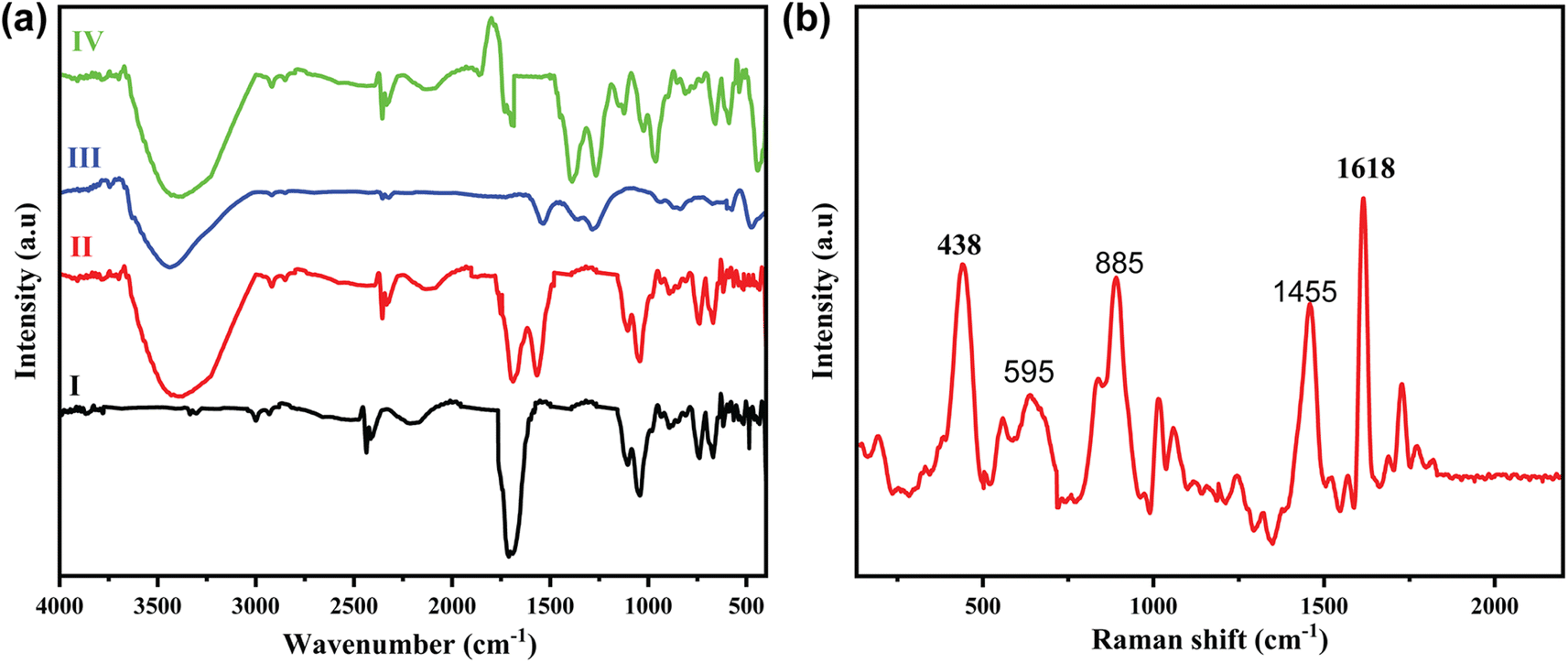 | ||
| Fig. 2 (a) FT-IR spectra of (I) BDC, (II) ZnO, (III) Co-BDC MOF and (IV) ZnO@Co-BDC composite and (b) Raman spectra of ZnO@Co-BDC MOF. | ||
The Raman spectra of the ZnO@Co-BDC composite were recorded in the range of 130–2300 cm−1, as illustrated in Fig. 2b, and provide valuable insights into its structural composition. The spectrum exhibits a prominent peak at approximately 1618 cm−1, attributed to the CC stretching mode of the BDC linker in the Co-BDC MOF, alongside smaller peaks at ∼1455 cm−1 (symmetric COO− stretching) and ∼1000–1200 cm−1 (C–H bending), confirming the presence of the MOF structure.46 For ZnO, a characteristic peak at ∼438 cm−1 corresponds to the E2 (high) mode of its wurtzite structure, with an additional feature at ∼595 cm−1 indicative of the E1 (longitudinal optical) mode, suggesting the presence of defects such as oxygen vacancies.47,48 These defects are beneficial for photocatalytic applications, enhancing charge separation and ROS generation. The relative intensity of the Co-BDC peaks suggests a dominant contribution from the MOF, while the ZnO peaks indicate its crystalline retention within the composite. Minimal peak shifts or new features suggest that the interaction between ZnO and Co-BDC is primarily physical, likely involving ZnO NPs embedded in the MOF framework, supporting their synergistic role in environmental remediation applications.
3.2. Optical properties of ZnO@Co-BDC composite catalysts
UV-Vis DRS were employed to assess the light absorption properties of ZnO, Co-BDC MOF, and ZnO@Co-BDC composite catalyst, with the results presented in Fig. 3. The data reveal that the absorption edges of ZnO and Co-BDC MOF are approximately 292 nm and 415 nm, respectively, while the absorption edge of the ZnO@Co-BDC composite is around 329 nm (Fig. 3a). This indicates that ZnO nanoparticles demonstrate broad absorption in the UV region due to their wide bandgap, whereas pure Co-BDC MOF absorbs in the visible range. Consequently, the combination of ZnO and Co-BDC MOF effectively enhances light utilization and improves the dye degradation efficiency. The optical bandgap energy of the synthesized photocatalyst samples was determined using Tauc plots (Fig. 3b) by extrapolating the absorption edge, applying the following equation (eqn (1)) for direct allowed transitions.49| (αhν)s = A(hν − Eg) | (1) |
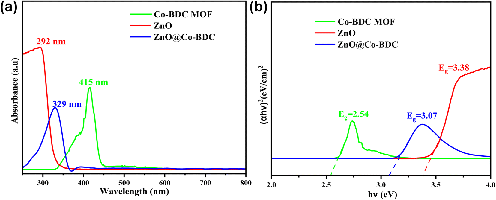 | ||
| Fig. 3 (a) UV-Vis absorption spectrum of the as-prepared samples and (b) the (αhv)2 − hv plot derived from the UV-Vis absorption spectrum. | ||
3.3. Photocatalytic activities of photocatalysts
Recently, photocatalysts activated by visible light have proven to be effective candidates for the photodegradation of organic dyes in aqueous solutions.50 The ZnO@Co-BDC composite catalyst demonstrates significantly higher photocatalytic efficiency compared to ZnO and Cu-BDC MOF. The photocatalytic activity of the ZnO@Co-BDC composite was evaluated through the degradation of MB. To achieve this, the ZnO@Co-BDC composite photocatalyst was incubated with MB dye under visible light irradiation.ZnO, Co-BDC MOF, and ZnO@Co-BDC composite successfully degraded MB, with its concentration declining over time. The degradation process occurred under visible light treatment for 80 min using a tungsten halogen lamp, with a 20 min interval between each exposure time. As compared to individual ZnO (Fig. 4a) and Co-BDC MOF (Fig. 4b), the ZnO@Co-BDC composite (Fig. 4c) showed the highest efficiency for the degradation of MB after 80 min under visible light treatments. In Fig. 4c, after 80 min, the MB solution incubated with the ZnO@Co-BDC composite catalyst exhibited the lowest absorbance as compared to MB solutions incubated with ZnO and Co-BDC MOF. The photographs in Fig. 4d depict the ZnO@Co-BDC composite before and after incubation in an MB solution. Upon irradiation, the blue color of the MB solution gradually disappears over time, aligning with the results observed in the absorbance spectra.
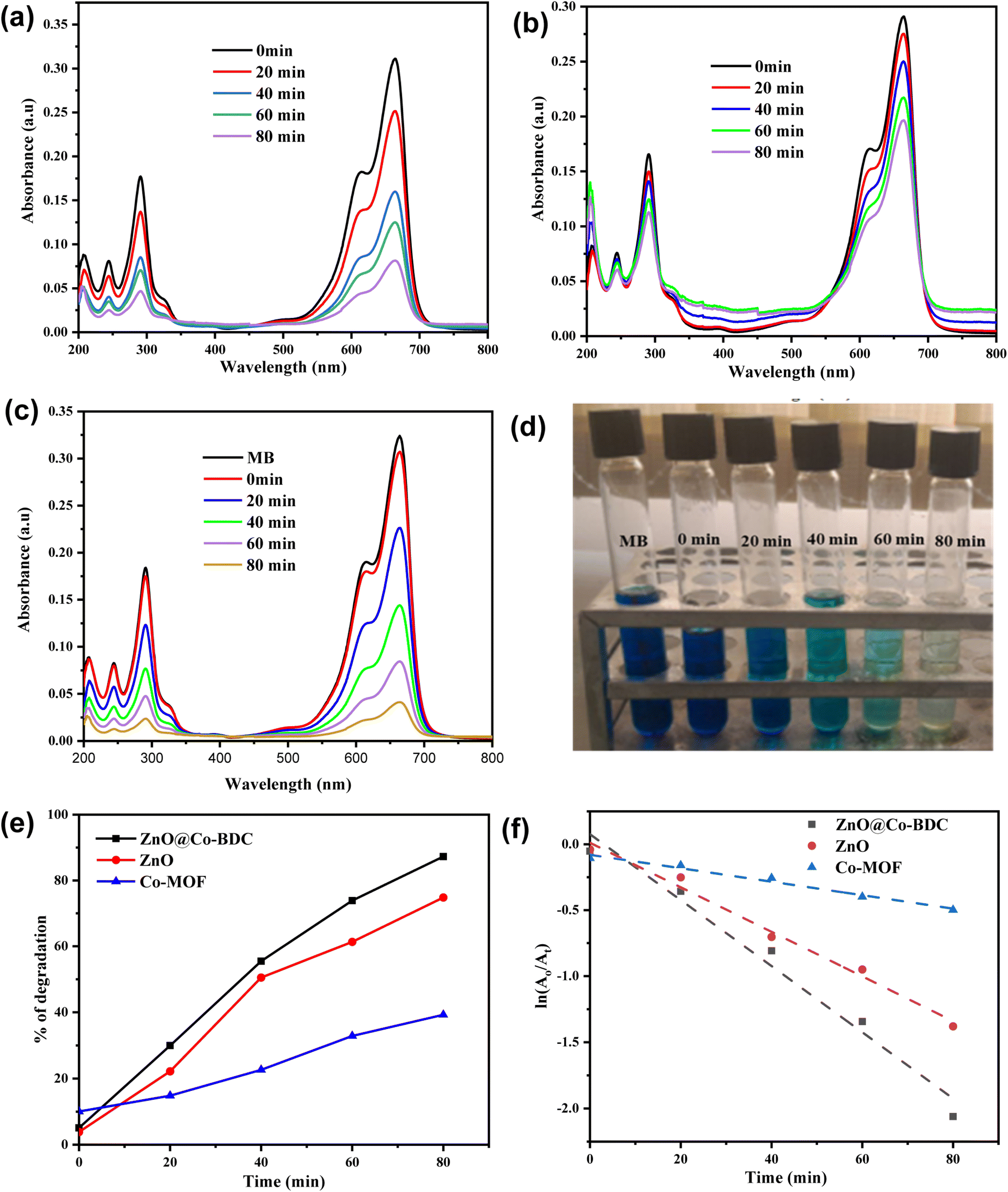 | ||
| Fig. 4 UV-visible absorption spectra of MB at various irradiation times using (a) ZnO, (b) Co-BDC MOF, and (c) ZnO@Co-BDC composite. (d) Photographs of MB before and after incubation with the ZnO@Co-BDC composite at different time intervals. (e) Degradation efficiencies (%) of MB. (f) First-order kinetics of the photocatalyst under visible light irradiation. | ||
The percentage degradation (%D) of MB is calculated using eqn (2).
 | (2) |
As shown in Fig. 4e, the percentage degradation of MB using the ZnO@Co-BDC composite is higher (87.5%), as compared to ZnO (74%) and Co-BDC (39%). ZnO shows lower degradation of MB under visible light because of its suboptimal utilization of visible light due to its wider band gap energy. In contrast, the Co-BDC MOF exhibits a significantly lower degradation rate of 39%, suggesting that it is less effective in photocatalytic applications on its own, likely due to inefficient charge separation. Remarkably, the ZnO@Co-BDC composite shows the highest degradation efficiency, indicating a synergistic effect that enhances photocatalytic activity. This improvement highlights the benefits of combining ZnO with Co-BDC MOF, as the composite takes advantage of the high surface area and porosity of the MOF to facilitate better dye absorption and efficient charge carrier separation. In addition, the moderate band gap (3.07 eV), which is low enough for the electrons to be excited with the low-energy visible light and high enough to reduce the recombination rate, enhances the activity.51 Furthermore, the degradation efficiency of the ZnO@Co-BDC composite is superior and similar to those of formerly reported photocatalysts, as indicated in Table S1.†
3.4. Kinetic analysis of MB dye degradation
To predict the degradation mechanism, a kinetics study is essential in wastewater treatment.52 In many studies, the photodegradation of pollutants follows a pseudo-first-order kinetic model. This model illustrates the relationship between the decomposition rate and time under particular reaction conditions.53 Therefore, in this study, pseudo-first-order kinetics were used to assess the equilibrium data. The photodegradation experiments were conducted using the UV-Vis spectra by recording the absorbance of MB solutions at various exposure times (Fig. 4). The (A/A0) values were measured to indicate the amount of MB molecules degraded using the maximum absorption spectra. Then, the kinetics of MB degradation was analyzed by a graph of ln(A/A0) versus time, as shown in Fig. 4f. The rate of MB dye removal was confirmed using eqn (3).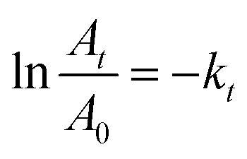 | (3) |
3.5. Effect of the operational parameters
 | ||
| Fig. 5 (a) UV-Vis spectra of MB with light treatment and without any catalyst. (b) Degradation of MB (%) with light treatment and without any catalyst. (c) UV-Vis spectra of MB incubated with the ZnO@Co-BDC composite catalyst under dark conditions. (d) Degradation of MB (%) incubated with the ZnO@Co-BDC composite catalyst under dark conditions. (e) UV-Vis spectra of MB incubated with the ZnO@Co-BDC composite catalyst under light irradiation. (f) Degradation of MB (%) incubated with the ZnO@Co-BDC composite catalyst under light irradiation. | ||
 | ||
| Fig. 6 (a) UV-Vis spectra for the degradation of MB at different pH values. (b) Degradation of MB (%) at different pH values. (c) UV-Vis spectra for the degradation of MB at different ZnO@Co-BDC doses. (d) Degradation of MB (%) at different ZnO@Co-BDC doses. (e) UV-Vis spectra for the degradation of MB (%) at different MB concentrations. (f) Degradation of MB (%) at different MB concentrations. | ||
3.6. Stability and reusability
The stability of the ZnO@Co-BDC composite photocatalyst was investigated by recycling the catalyst for six cycles. The photodegradation of MB was conducted at optimal conditions, and the photocatalyst was regenerated with ethanol, then centrifuged and dried at 80 °C before being used in the next cycle. The results, as displayed in Fig. 7a, indicated that the photocatalyst could be easily regenerated with only a minimal change in intensity after being recycled for six cycles. During the recycling process, the photodegradation of the ZnO@Co-BDC composite catalyst resulted in a MB degradation of 91%, 90.5%, 88.1%, 86.4%, 83.2%, and 80.5% (Fig. 7a), from the first cycle to the six cycles, respectively, indicating a slight reduction in the photocatalytic efficiency after six cycles. This slight decrease in activity was attributed to the inactivation of certain adsorption sites on the surface of the photocatalyst or a partial phase alteration of the dye solution activated by the photocatalyst in the presence of light. After completing each cycle (1st–6th) of photocatalytic degradation, the ZnO@Co-BDC MOF was subjected to structural evaluation using XRD (Fig. S2†), revealing no noticeable changes in the phases of the composite catalyst at any stage, indicating its phase integrity throughout the process. Additionally, the XRD spectrum of Co-BDC MOF after the first cycle (Fig. S3†) showed no deviation from its original spectrum before degradation, further confirming the stability of the MOF component. To complement this, FTIR analysis of the ZnO@Co-BDC composite was conducted after six cycles (Fig. S4†), verifying the retention of both Co-BDC MOF and ZnO phases, thus confirming the structural integrity of the composite. However, the XRD spectra of both ZnO@Co-BDC revealed a decrease in peak intensity, suggesting that MB molecules were adsorbed onto the catalyst surface during the degradation process. Despite this adsorption, the unchanged peak positions and widths in the XRD patterns indicate that the crystallinity of the photocatalyst remained intact, demonstrating the robustness of the ZnO@Co-BDC MOF under repeated photocatalytic cycles. These results indicate that it can be an effective photocatalyst for the photodegradation of MB and has recyclable properties. | ||
| Fig. 7 Degradation percentage of MB (a) by reuse of ZnO@Co-BDC over six cycles (b) in the presence of different scavengers and (c) proposed photocatalytic degradation mechanisms of MB dye using the ZnO@Co-BDC composite catalyst. | ||
3.7. Scavenger test
A mechanism for the photocatalytic degradation of MB using ZnO@Co-BDC composite was explored by using various scavengers to capture free radicals. Isopropanol was utilized as a scavenger for hydroxyl radicals (˙OH), BQ for superoxide radicals (˙O2−), and EDTA for holes (h+).60 In this study, different scavengers were used to clarify the role of the reactive oxygen species in the degradation of MB by trapping the free radicals. As shown in Fig. 7b, different scavengers, such as isopropanol, EDTA, and BQ, were used to assess the impact of the reactive oxygen species (˙OH, h+ and ˙O2−) generated by the ZnO@Co-BDC composite catalyst in degrading MB under visible light. The results indicate that the photocatalytic efficiency of the ZnO@Co-BDC composite catalyst decreased significantly when EDTA-2Na was used, compared to the effects of BQ or isopropanol. The ZnO@Co-BDC catalyst removed 65%, 31%, 34%, and 91% of the MB dye using of isopropanol, EDTA, BQ, and without the catalyst, respectively (Fig. 7b). This suggests that positive holes (h+) and ˙O2− radicals play a major role in breaking down the MB dye, while ˙OH contributes less to this process.3.8. Degradation mechanism
Fig. 7c presents a schematic representation of the mechanism for the photodegradation of MB using the ZnO@Co-BDC composite catalyst. It can be seen from the results that the photocatalytic degradation ability of the ZnO@Co-BDC composite catalyst is higher than that of the Co-BDC MOF and pristine ZnO. On this basis, a mechanism for the photocatalytic degradation of MB by the ZnO@Co-BDC composite sample is proposed. The ZnO@Co-BDC composite sample, with a lower gap width than Co-BDC MOF, is more likely to accept lower photon energy intensity. The electrons in the valence band (VB) (e−) jump into the conduction band (CB) through the gap and form a photogenerated carrier hole (e−, h+).61 The photogenerated electrons on CB are transferred to VB on the material surface, e− reacts with O2 in the solution to generate·O2−, and ˙O2− reacts with MB to generate intermediate substances and then generates small molecular substances. On the other hand, h+ on VB directly reacts with MB, and then catalyzes MB degradation to increase the capacity of the composite sample for photocatalysis.The VB energy (EVB) and CB energy (ECB) of ZnO and Co-BDC MOF were determined using the absolute electronegativity (x) of each catalyst using eqn (4) and (5).62
| EVB = x − Ee − 0.5Eg | (4) |
| ECB = EVB − Eg | (5) |
4. Conclusion
In conclusion, we have reported a ZnO@Co-BDC composite prepared using the solvothermal method for MB degradation. The ZnO@Co-BDC composite exhibited significantly enhanced photocatalytic efficiency compared to pristine ZnO and Co-BDC MOF for the degradation of MB dye in aqueous solution under visible light irradiation. The incorporation of the Co-BDC MOF with ZnO nanoparticles altered the band structure of the composite, leading to improved photodegradation performance. The ZnO@Co-BDC composite achieved the highest degradation efficiency of MB, reaching 87.5% within 80 minutes under visible light exposure. In comparison, pristine ZnO and Co-BDC MOF demonstrated degradation efficiencies of 74% and 39%, respectively. Furthermore, the kinetic study also indicated that the degradation of MB followed first-order kinetics with a rate constant of 2.501 × 10⁻² min−1. Factors that influence the degradation efficiencies, such as laser irradiation, catalyst dose, solution pH, and dye concentration, were also demonstrated. The stability and reusability of the ZnO@Co-BDC composite were evaluated and found to be effective for up to six cycles, which demonstrated better stability and reusability. Overall, the synthesized ZnO@Co-BDC composite catalyst has the potential to act as an alternative photocatalyst for MB degradation under visible light. Additionally, this MOF-based composite catalyst enabled the simultaneous valorization of plastic waste and remediation of environmental pollutants by converting waste to wealth.Data availability
The datasets used in this study are accessible in the publication and can be obtained upon request from the corresponding author.Conflicts of interest
The authors declare no conflict of interest.Acknowledgements
The authors would like to thank Wollo University for financial support through a small research grant and for providing the resources for this study. The authors acknowledge Adama Science and Technology University for XRD and photocatalytic performance analysis, National Taiwan University of Science and Technology for Raman spectra, and National Taiwan University for TEM analysis.References
- W. Zhao, M. Adeel, P. Zhang, P. Zhou, L. Huang, Y. Zhao, M. A. Ahmad, N. Shakoor, B. Lou and Y. Jiang, Environ. Sci.:Nano, 2022, 9, 61–80 RSC.
- M. F. Hanafi and N. Sapawe, Mater. Today: Proc., 2020, 31, A141–A150 Search PubMed.
- K. Maheshwari, M. Agrawal and A. Gupta, in Novel Materials for Dye-Containing Wastewater Treatment, ed. A. K. Subramanian Senthilkannan Muthu, Springer, Singapore, 2021, pp. 1–25 Search PubMed.
- R. Al-Tohamy, S. S. Ali, F. Li, K. M. Okasha, Y. A. Mahmoud, T. Elsamahy, H. Jiao, Y. Fu and J. Sun, Ecotoxicol. Environ. Saf., 2022, 231, 113160 CrossRef CAS PubMed.
- W. M. Alamier, N. Hasan, I. S. Syed, A. M. Bakry, K. S. Ismail, G. Gedda and W. M. Girma, Catalysts, 2023, 13, 1290 CrossRef CAS.
- M. B. Tahir, T. Iqbal, M. Rafique, M. S. Rafique, T. Nawaz and M. Sagir, in Nanotechnology and Photocatalysis for Environmental Applications, ed. M. S. R. Muhammad Bilal Tahir and M. Rafique, Elsevier, 2020, pp. 65–76 Search PubMed.
- R. Gusain, K. Gupta, P. Joshi and O. P. Khatri, Adv. Colloid Interface Sci., 2019, 272, 102009 CrossRef CAS PubMed.
- B. A. Berehe, A. H. Assen, A. S. K. Kumar, H. Ulla, A. D. Duma, J. Y. Chang, G. Gedda and W. M. Girma, Sci. Rep., 2023, 13, 16454 CrossRef CAS PubMed.
- F. Zhang, X. Wang, H. Liu, C. Liu, Y. Wan, Y. Long and Z. Cai, Appl. Sci., 2019, 9, 2489 CrossRef CAS.
- D. Chen, Y. Cheng, N. Zhou, P. Chen, Y. Wang, K. Li, S. Huo, P. Cheng, P. Peng and R. Zhang, J. Cleaner Prod., 2020, 268, 121725 CrossRef CAS.
- X. Liu, R. Ma, L. Zhuang, B. Hu, J. Chen, X. Liu and X. Wang, Crit. Rev. Environ. Sci. Technol., 2021, 51, 751–790 CrossRef CAS.
- S. Sakthivel, B. Neppolian, M. Shankar, B. Arabindoo, M. Palanichamy and V. Murugesan, Sol. Energy Mater. Sol. Cells, 2003, 77, 65–82 CrossRef CAS.
- L. Yao, H. Yang, Z. Chen, M. Qiu, B. Hu and X. Wang, Chemosphere, 2021, 273, 128576 CrossRef CAS PubMed.
- C. B. Ong, L. Y. Ng and A. W. Mohammad, Renewable Sustainable Energy Rev., 2018, 81, 536–551 Search PubMed.
- J. Z. Hassan, A. Raza, U. Qumar and G. Li, Sustainable Mater. Technol., 2022, 33, e00478 CrossRef CAS.
- F. Sanakousar, C. Vidyasagar, V. Jiménez-Pérez and K. Prakash, Mater. Sci. Semicond. Process., 2022, 140, 106390 CrossRef CAS.
- F. Wang, Y. Zhou, X. Pan, B. Lu, J. Huang and Z. Ye, Phys. Chem. Chem. Phys., 2018, 20, 6959–6969 RSC.
- S. J. Yang, J. H. Im, T. Kim, K. Lee and C. R. Park, J. Hazard. Mater., 2011, 186, 376–382 CrossRef CAS PubMed.
- A. H. Chughtai, N. Ahmad, H. A. Younus, A. Laypkov and F. Verpoort, Chem. Soc. Rev., 2015, 44, 6804–6849 RSC.
- L. Jiao, J. Y. R. Seow, W. S. Skinner, Z. U. Wang and H.-L. Jiang, Mater. Today, 2019, 27, 43–68 Search PubMed.
- J. Buasakun, P. Srilaoong, K. Chainok, C. Raksakoon, R. Rattanakram and T. Duangthongyou, Inorg. Chim. Acta, 2020, 511, 119839 CrossRef CAS.
- Z. Zhang, C. J. R. Wells, A. M. King, J. C. Bear, G. L. Davies and G. R. Williams, J. Mater. Chem. B, 2020, 8, 7264–7274 RSC.
- S. Chen, Y. Li and L. Mi, Inorg. Chem. Commun., 2020, 118, 107999 CrossRef CAS.
- C. V. Reddy, K. R. Reddy, V. a. Harish, J. Shim, M. Shankar, N. P. Shetti and T. M. Aminabhavi, Int. J. Hydrogen Energy, 2020, 45, 7656–7679 Search PubMed.
- R. R. Ikreedeegh and M. Tahir, J. CO2 Util., 2021, 43, 101381 Search PubMed.
- I. I. Alkhatib, C. Garlisi, M. Pagliaro, K. Al-Ali and G. Palmisano, Catal. Today, 2020, 340, 209–224 Search PubMed.
- H.-P. Jing, C.-C. Wang, Y.-W. Zhang, P. Wang and R. Li, RSC Adv., 2014, 4, 54454–54462 RSC.
- X. Qin, T. Qiang, L. Chen and S. Wang, Microporous Mesoporous Mater., 2021, 315, 110889 CrossRef CAS.
- D. Sun, L. Ye and Z. Li, Appl. Catal., B, 2015, 164, 428–432 CrossRef CAS.
- Y. Gao, S. Li, Y. Li, L. Yao and H. Zhang, Appl. Catal., B, 2017, 202, 165–174 CrossRef CAS.
- M. Wen, K. Mori, T. Kamegawa and H. Yamashita, Chem. Commun., 2014, 50, 11645–11648 RSC.
- Y. Wu, X. Li, H. Zhao, F. Yao, J. Cao, Z. Chen, D. Wang and Q. Yang, Chem. Eng. J., 2021, 426, 131255 CrossRef CAS.
- D. Sun, Y. Fu, W. Liu, L. Ye, D. Wang, L. Yang, X. Fu and Z. Li, Chem.–Eur. J., 2013, 19, 14279–14285 Search PubMed.
- M. G. Kibria, N. I. Masuk, R. Safayet, H. Q. Nguyen and M. Mourshed, Int. J. Environ. Res., 2023, 17, 20 Search PubMed.
- R. Kaur, A. Marwaha, V. A. Chhabra, K. Kaushal, K.-H. Kim and S. Tripathi, J. Cleaner Prod., 2020, 263, 121492 Search PubMed.
- T. Sivam, N. Gowthaman, H. Lim, Y. Andou, P. Arul, E. Narayanamoorthi and S. A. John, Colloids Surf., A, 2021, 622, 126667 Search PubMed.
- S. Bagheri, K. Chandrappa and S. Hamid, Pharma Chem., 2013, 5, 265–270 Search PubMed.
- O. A. Zelekew, P. A. Fufa, F. K. Sabir and A. D. Duma, Heliyon, 2021, 7, e07652 Search PubMed.
- A. Dehdar, G. Asgari, M. Leili, T. Madrakian and A. Seid-Mohammadi, J. Environ. Manage., 2021, 297, 113338 CrossRef CAS PubMed.
- Y. Wang, H. Wang, S. Li and S. Sun, ACS Omega, 2022, 7, 35180–35190 CrossRef CAS PubMed.
- A. Noruozi and A. Nezamzadeh-Ejhieh, Chem. Phys. Lett., 2020, 752, 137587 Search PubMed.
- Y. Rao, G. Inwati and M. Singh, Future Sci. OA, 2017, FSO239 Search PubMed.
- D. D. Thongam, J. Gupta and N. K. Sahu, Appl. Sci., 2019, 1, 1030 CAS.
- R. Yuniasari, F. Amri, S. A. Abrori, N. L. W. Septiani, M. Rezki, M. Fahmi and B. Yuliarto, IOP Conf. Ser.: Mater. Sci. Eng., 2021, 1045, 012010 Search PubMed.
- X. Hu, H. Hu, C. Li, T. Li, X. Lou, Q. Chen and B. Hu, J. Solid State Chem., 2016, 242, 71–76 Search PubMed.
- S. Ramalingam and S. Periandy, Spectrochim. Acta, Part A, 2011, 78, 1149–1161 CrossRef CAS PubMed.
- L. Shi, Raman Spectroscopy Study of Wurtzite Crystals: Gallium Nitride and Zinc Oxide, Arizona State University, 2003 Search PubMed.
- M. Šćepanović, M. Grujić-Brojčin, K. Vojisavljević, S. Bernik and T. Srećković, J. Raman Spectrosc., 2010, 41, 914–921 CrossRef.
- M. Fiaz, M. Kashif, S. Majeed, M. N. Ashiq, M. A. Farid and M. Athar, ChemistrySelect, 2019, 4, 6996–7002 CrossRef CAS.
- S. Li, Z. Wang, X. Zhao, X. Yang, G. Liang and X. Xie, Chem. Eng. J., 2019, 360, 600–611 CrossRef CAS.
- E. Amdeha and R. S. Mohamed, Environ. Technol., 2021, 42, 842–859 Search PubMed.
- H. Yu, E. Nie, J. Xu, S. Yan, W. J. Cooper and W. Song, Water Res., 2013, 47, 1909–1918 CrossRef CAS PubMed.
- R. Ezzati, Chem. Eng. J., 2020, 392, 123705 CrossRef CAS.
- A. K. Sajjad, S. Shamaila, B. Tian, F. Chen and J. Zhang, J. Hazard. Mater., 2010, 177, 781–791 CrossRef CAS PubMed.
- K. G. Akpomie, J. Conradie, K. A. Adegoke, K. O. Oyedotun, J. O. Ighalo, J. F. Amaku, C. Olisah, A. O. Adeola and K. O. Iwuozor, Appl. Water Sci., 2023, 13, 20 CrossRef CAS.
- K. M. Reza, A. Kurny and F. Gulshan, Appl. Water Sci., 2017, 7, 1569–1578 CrossRef CAS.
- T. B. Adamu, A. M. Mengesha, M. A. Kebede, B. L. Bogale and T. W. Kassa, Results Chem., 2024, 10, 101724 CrossRef.
- I. Groeneveld, M. Kanelli, F. Ariese and M. R. van Bommel, Dyes Pigm., 2023, 210, 110999 CrossRef CAS.
- A. Ajmal, I. Majeed, R. N. Malik, H. Idriss and M. A. Nadeem, RSC Adv., 2014, 4, 37003–37026 RSC.
- R. Guo, Y. Wang, J. Li, X. Cheng and D. D. Dionysiou, Appl. Catal., B, 2020, 278, 119297 CrossRef CAS.
- W. Sun, S. Meng, S. Zhang, X. Zheng, X. Ye, X. Fu and S. Chen, J. Phys. Chem. C, 2018, 122, 15409–15420 CrossRef CAS.
- A. Naseri, M. Samadi, N. M. Mahmoodi, A. Pourjavadi, H. Mehdipour and A. Moshfegh, J. Phys. Chem., 2017, 121, 3327–3338 CrossRef CAS.
- Z. Yu, H. Moussa, M. Liu, R. Schneider, M. Moliere and H. Liao, Surf. Coat. Technol., 2019, 375, 670–680 CrossRef CAS.
- N. K. Sompalli, Y. Li, J. Li and S. Kuppusamy, Environ. Res., 2024, 259, 119532 CrossRef CAS PubMed.
Footnote |
| † Electronic supplementary information (ESI) available. See DOI: https://doi.org/10.1039/d4na01071j |
| This journal is © The Royal Society of Chemistry 2025 |