
 Open Access Article
 This Open Access Article is licensed under a Creative Commons Attribution-Non Commercial 3.0 Unported Licence
Evaluating CO2-to-formic acid electrocatalysts in different device configurations†
Thuy-Duong Nguyen-Phan *a,
James E. Ellisab,
Bret H. Howarda and
Douglas R. Kauffman*a
*a,
James E. Ellisab,
Bret H. Howarda and
Douglas R. Kauffman*a
aNational Energy Technology Laboratory, 626 Cochran Mill Road, Pittsburgh, PA 15236, USA. E-mail: ThuyDuong.NguyenPhan@netl.doe.gov; Douglas.Kauffman@netl.doe.gov
bNETL Support Contractor, 626 Cochran Mill Road, Pittsburgh, PA 15236, USA
First published on 10th July 2025
Abstract
We evaluated CO2 electroreduction differences of three materials in aqueous H-cell, gas diffusion electrode (GDE) half-cell, and full-cell electrolyzer devices. Mass-transport limited catalyst differences in H-cells become more apparent in gas-fed GDE half-cells; however, voltage contributions from device components can mask cathode differences in full-cell devices until high current density.
Low temperature electrochemical CO2 reduction (CO2R) is a promising approach to convert a low-value waste gas into industrially-relevant chemicals.1–5 Liquid formic acid (FA) is one product of interest with use in fuel cells, agricultural, chemicals, and pharmaceutical applications.2,3,6–13 Recent efforts have focused on improving FA production through electrocatalyst development and optimizing the operating conditions, cell components, and device configuration.3–5,8–10,12–19 However, differences between the electrochemical device architectures used to screen and validate CO2R electrocatalysts makes it difficult to evaluate material improvements and compare against literature results.
CO2R reports have historically used aqueous H-cells filled with CO2 saturated aqueous catholyte to screen and demonstrate electrocatalyst materials.3,8–10,20 However, the low solubility (34.2 mmol L−1) and diffusivity (∼2 × 10⁻⁹ m2 s−1) of CO2 dissolved in aqueous electrolyte20,21 limits current densities and this device configuration does not represent a deployable full-cell electrolyzer design. The field has subsequently shifted to gas diffusion electrodes (GDEs) that deliver gaseous CO2 to the cathode for more efficient mass transfer, better catalyst utilization, and the ability to achieve industrially relevant current densities.1,3,4,9,10,13,14,16,18,19,22
GDE half-cells largely mimic full-cell device architectures but include a reference electrode to quantify cathode voltages and kinetics. The cathode voltages can be corrected for the iR drop associated with uncompensated solution resistance (Ecathode-iR) and referenced against the reversible hydrogen electrode (RHE). Both zero-gap (cathode directly interfaced to an ion exchange membrane) and single-gap (thin flowing catholyte layer separating cathode and membrane) full-cell electrolyzer devices have been demonstrated for CO2 to FA.4,9–11,18–20,22–24 The reported full-cell voltage (Ecell) represents the absolute anode–cathode voltage difference and includes contributions from the cathode, anode, membrane and catholyte (if used) that are difficult to deconvolute.
It is common to see catalyst screening studies conducted in H-Cell or GDE half-cell devices, but it is not often shown how apparent catalyst performance differences translate between aqueous H-cell, GDE half-cell, and full cell device architectures. In this work, we compared the CO2R to FA performance of commercially-available SnO2, Bi2O3, and In2O3 electrocatalysts in aqueous H-cell, GDE half-cell, and full cell device configurations to understand how device architecture impacts apparent catalyst activity (Fig. S1 and S2, ESI†). Tin, bismuth, and indium-based materials are well known electrocatalysts to convert CO2 into formic acid or formate and they have been commonly investigated in various cell configurations.9–12,16,24–26
Detailed methods are described in the ESI,† but briefly, aqueous H-cells contained a 0.075 cm2 cathode and Ag/AgCl reference electrode submerged in 60 mL of CO2-saturated 0.4 M K2SO4 catholyte, a Nafion 117 membrane, and a Pt mesh anode in 0.4 M K2SO4 anolyte. GDE half-cell and full-cell experiments were conducted using commercially-available hardware (Dioxide Materials), a 6.25 cm2 cathode supplied with gaseous CO2, a flowing 0.4 M K2SO4 catholyte chamber (half-cell ∼1.9 mL volume, full cell ∼1.0 mL volume), a Nafion N324 membrane, an IrO2 anode and flowing deionized H2O anolyte. The bulk catholyte pH in H-cell experiments was around 5.5 and the FA product was detected in the ionic formate form, while the GDE half-cell and full-cell experiments produced a more acidified FA product stream (pH 2.5–4.5). However, we simply refer to the product as FA in all cases. A miniature reversible hydrogen reference electrode was inserted into the flowing catholyte chamber to quantify GDE half-cell cathode potentials. All H-Cell and GDE half-cell and cathode potentials were 100% iR-corrected for the uncompensated resistance and referenced against the RHE scale.27 Full-cell Ecell values were not corrected.
Typical figures of merit for H-cell and GDE half-cell experiments include the product faradaic efficiency (FE) and partial current density versus Ecathode-iR (V vs. RHE), where FE and partial current density represent the fraction of the total electrons and current density used to form the product (eqn (S1) and (S2), ESI†). Fig. 1 summarizes the FA partial current density and formic acid FE (FEFA) versus the cathode potential for Bi2O3, SnO2 and In2O3 in the aqueous H-cell and GDE half-cell devices. All three catalysts demonstrated similar apparent CO2R onset potentials, Tafel slopes, and partial current densities in the H-Cell (Fig. 1A, B and Fig. S3A, ESI†). They all demonstrated initially low FEFA values at smaller cathode overpotentials that increased towards larger overpotentials, but SnO2 showed consistently lower FEFA than Bi2O3 and In2O3 due to higher H2 and CO formation (Fig. S4, ESI†). Bi2O3 produced slightly higher partial current density than In2O3 and SnO2 at some potentials, but the similar current density profiles suggest mass transport limitations associated with converting dissolved CO2 may hinder the apparent catalyst activity towards larger cathode potentials.
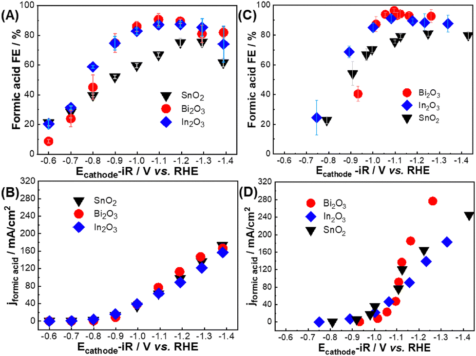 | ||
| Fig. 1 Formic acid FE and partial current densities as function of iR-corrected cathode potential (Ecathode-iR) for Bi2O3, In2O3, and SnO2 in (A, B) aqueous H-cell and (C, D) GDE half-cell configurations. Note that same Y-axis and X-axis scales were plotted for (B) and (D) panels to clearly demonstrate the difference between aqueous H-cell and GDE half-cell current densities over a similar potential range. GDE half-cell results over a larger potential range are shown in Fig. S4 (ESI†). | ||
Fig. 1C, D and Fig. S5, S6 (ESI†) compare catalyst performance in the GDE half-cell device over a comparable Ecathode-iR range used for H-cell experiments. The catalysts demonstrated a similar FEFA trend that increased with cathode potential (Fig. 1C). Bi2O3 and In2O3 both demonstrated >90% FEFA between −1.1 V and −1.4 V vs. RHE, but SnO2 plateaued around 80% FEFA. Notably, the catalysts produced larger current density in the gas-fed GDE half-cell configuration than in the H-Cell (Fig. 1D). Bi2O3 partial current density now obviously exceeded SnO2 and In2O3 at higher overpotentials, albeit with a larger apparent CO2R onset potential than the other catalysts. GDE half-cell results also revealed that the linear Tafel region extended to larger partial current densities than in the H-cell device (Fig. S3, ESI†). This observation points towards reduced mass transfer limitations in the gas-fed GDE half-cell, and differences in CO2R activity between the three catalysts are now well observed. Taken together, the results in Fig. 1 suggest H-cell devices may mask intrinsic catalyst activity differences and identify gas-fed GDE half-cell device as a better choice for comparing catalysts’ cathodic CO2R performance.
We have shown that GDE half-cells can differentiate cathodic catalyst performance more clearly than H-cells, but the literature does not often discuss how cathodic CO2R catalyst activity differences translate to full-cell devices. Fig. 2 and Fig. S5–S7 (ESI†) confirm that the three catalysts individually showed similar partial current densities and FEFA in the GDE half- and full-cell configurations. In this convention, the partial current density (left axis) and FEFA (right axis) are plotted as a function of total applied current density, and deviations between the applied and partial current densities represent reduced FEFA. Bi2O3 maintained high FEFA around 90% between 50–500 mA cm−2 applied current density and produced a maximum FA partial current density between 400–460 mA cm−2 in both GDE half-cell and full-cell devices. In2O3 and SnO2 demonstrated reduced (60–80%) FEFA at applied current densities >400 mA cm−2 that limited their maximum FA partial current density to 250–400 mA cm−2 in both GDE half-cell and full cell devices.
 | ||
| Fig. 2 Comparison of FA partial current densities and FEFA for all three catalysts as a function of applied current density in half-cell (hollow) and full cell (solid). | ||
Catalysts did show lower maximum partial current density in the GDE-half cell device than in the full-cell device. We hypothesize this may stem from mass transport differences associated with thicker catholyte flow chamber used to house the reference electrode in the GDE half-cell device (3 mm thick chamber, 1.9 mL flowing catholyte volume) compared with the thinner catholyte chamber used in full-cell device experiments (1.6 mm thick chamber, 1 mL flowing catholyte volume). However, these results do show that both GDE half-cell and full cell devices can produce similar FEFA up to very large current densities.
Full-cell Ecell values include resistance contributions from the anode, ion exchange membrane, cell hardware and solution resistance, and Fig. 3A demonstrates that all three cathode catalysts operated with similar Ecell values in the full-cell device. We acknowledge these cell voltages are larger than typically shown for zero-gap devices, but these values and energy efficiencies (Fig. S7D, ESI†) are comparable to previous reports using similar flowing catholyte device configurations.3,8,10,13,20,28 The field is actively developing other device configurations (i.e. zero gap and MEA) and alternative anode reactions to reduce Ecell and improve energy efficiency.3,8–10,18,20,22,29,30
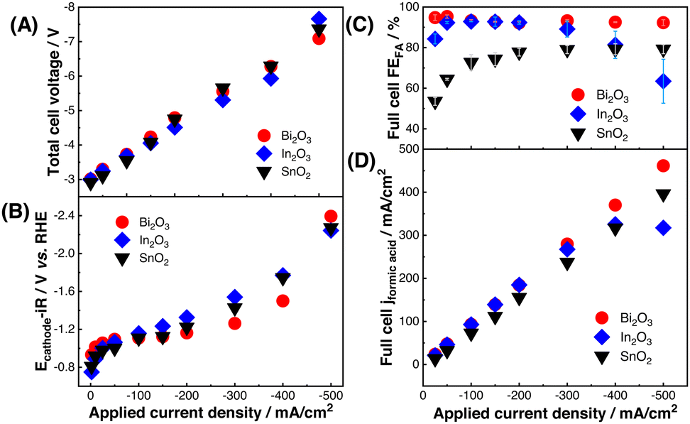 | ||
| Fig. 3 (A) Total full-cell cell voltages (Ecell) and (B) GDE half-cell iR-corrected cathode potentials (Ecathode-iR) versus total applied current density. Comparison of (C) FEFA and (D) FA partial current density versus total applied current density in the full-cell device for Bi2O3, In2O3, and SnO2. | ||
Fig. 3B also reports the GDE half-cell E-iRcathode values over the same applied current density range. While this comparison is not a quantitative voltage break down of the full-cell components,13 these results highlight that iR-corrected cathode voltage is small compared to the total full-cell Ecell. Moreover, the 100–300 mV E-iRcathode difference observed between catalysts in GDE half-cell experiments did not translate to meaningful changes in the full-cell Ecell values. This suggests that half-cell partial current density and E-iRcathode differences may not significantly impact single-gap, flowing catholyte full-cell performance unless those differences are very large.
The observation that catalyst Ecathode-iR differences do not significantly impact full-cell Ecell identifies FEFA as a key performance metric. Fig. 3C and D compare the full-cell performance of the three catalysts. Bi2O3 sustained >90% FEFA between 50–500 mA cm−2 applied current and it produced a maximum FA partial current density of ∼460 mA cm−2. In2O3 also sustained ∼90% FEFA up to 300 mA cm−2 applied current density, but decreasing FEFA above this point (60–80% FEFA) limited the In2O3 maximum partial current density to ∼320 mA cm−2. SnO2 FEFA never exceeded 80% in the full-cell device and its partial current density was consistently lower than Bi2O3. Both SnO2 and In2O3 also experienced particle agglomeration during electrolysis that may have further contributed to them producing lower maximum partial current density than Bi2O3, which transformed into two-dimensional sheet-like structures during CO2R (Fig. S8, ESI†).8,26 Fig. 3 results confirm that FEFA differences observed in GDE half-cell experiments translate to full-cell operation, whereas the catalysts’ potential-dependent partial current density and cathodic Ecathode-iR did not substantially impact full cell performance. We hypothesize the comparatively small contribution of Ecathode-iR to the total Ecell made FEFA deviations the main differentiator between catalyst performance in the full-cell device. In addition, good correlation between half-cell and full-cell partial current densities indicates that the half-cell performance can inform full-cell performance at moderate current densities (Fig. S9, ESI†).
Finally, Fig. 4 and Fig. S10 (ESI†) confirm the catalysts maintained good stability and selectivity over 24 hours of operation at 100 mA cm−2 applied current density in the full-cell device, with FEFA of 93 ± 2% for Bi2O3, 92 ± 1% for In2O3, and 78 ± 5% for SnO2 and total cell voltages between 3.8 and 4.3 V.
 | ||
| Fig. 4 Stability over 24 hours at 100 mA cm−2 in the full cell device. | ||
In summary, we evaluated three commercially-available CO2 to FA electrocatalysts in three commonly-used cell configurations, including H-cell, GDE half-cell and full-cell devices. Limitations associated with converting dissolved CO2 in H-cells limits catalyst performance and may mask inherent activity differences. Our results show that H-cell devices may be more appropriate for specialized studies, such as comparing soluble homogeneous catalysts, rotating disk electrode experiments, single-crystals, or catalysts grown on nonporous substrates.4,20,31,32 GDE half-cells appear to be a better tool for conducting cathode-specific kinetic studies. Their ability to produce current densities and product FEs that are comparable to full-cell devices make them a suitable screening tool to predict high-current density product selectivity in full-cells. One benefit of the single-gap, flowing catholyte GDE half-cell design is the relatively straight-forward method of isolating cathode voltages by incorporating a reference electrode into the central catholyte chamber, compared with more sophisticated membrane-based reference electrodes or anodic H2 oxidation approaches demonstrated in some full-cell architectures.18,22,29,30,33 However, this flowing catholyte architecture does increase full-cell Ecell values compared with zero-gap architectures.
Our results show that FE differences observed in half-cells do translate to full-cell performance, but that they may not become substantial in full-cell devices until higher current density regimes due to the other component's resistance contributions. We suggest that catalyst development studies should include both GDE half-cell and full-cell studies to fully characterize cathode kinetics and demonstrate the translatability of apparent material improvements in relevant device architectures. We hope this study will help researchers choose the most appropriate device hardware and methodology for screening formic acid producing CO2R catalysts in single-gap, flow catholyte electrolyzers.
This work was performed in support of the U.S. Department of Energy's Fossil Energy and Carbon Management's Carbon Conversion Program and executed through the National Energy Technology Laboratory (NETL) Research & Innovation Center's Carbon Utilization MYRP. This project was funded by the United States Department of Energy, National Energy Technology Laboratory, in part, through a site support contract. Neither the United States Government nor any agency thereof, nor any of their employees, nor the support contractor, nor any of their employees, makes any warranty, express or implied, or assumes any legal liability or responsibility for the accuracy, completeness, or usefulness of any information, apparatus, product, or process disclosed, or represents that its use would not infringe privately owned rights. Reference herein to any specific commercial product, process, or service by trade name, trademark, manufacturer, or otherwise does not necessarily constitute or imply its endorsement, recommendation, or favoring by the United States Government or any agency thereof. The views and opinions of authors expressed herein do not necessarily state or reflect those of the United States Government or any agency thereof.
Conflicts of interest
There are no conflicts to declare.Data availability
The data supporting this article have been included as part of the ESI,† including additional methods and results in Fig. S1–S10.Notes and references
- C. P. O’Brien, R. K. Miao, A. Shayesteh Zeraati, G. Lee, E. H. Sargent and D. Sinton, Chem. Rev., 2024, 124, 3648–3693 CrossRef PubMed.
- S. Zhai, S. Jiang, C. Liu, Z. Li, T. Yu, L. Sun, G. Ren and W. Deng, J. Phys. Chem. Lett., 2022, 13, 8586–8600 CrossRef CAS PubMed.
- A. Badgett, M. Ruth, A. Crow, G. Grim, Y. Chen, L. Hu, L. Tao, W. Smith, K. C. Neyerlin and R. Cortright, J. Cleaner Prod., 2022, 351, 131564 CrossRef CAS.
- S. Liang, N. Altaf, L. Huang, Y. Gao and Q. Wang, J. CO2 Util., 2020, 35, 90–105 CrossRef CAS.
- J. Herranz, A. Pătru, E. Fabbri and T. J. Schmidt, Curr. Opin. Electrochem., 2020, 23, 89–95 CrossRef CAS.
- J. Eppinger and K.-W. Huang, ACS Energy Lett., 2017, 2, 188–195 CrossRef CAS.
- B. S. Crandall, T. Brix, R. S. Weber and F. Jiao, Energy Fuels, 2022, 37, 1441–1450 CrossRef.
- J. Zou, G. Liang, C.-Y. Lee and G. G. Wallace, Mater. Today Energy, 2023, 38, 101433 CrossRef CAS.
- K. Fernández-Caso, G. Díaz-Sainz, M. Alvarez-Guerra and A. Irabien, ACS Energy Lett., 2023, 8, 1992–2024 CrossRef.
- Z. M. Ghazi, D. Ewis, H. Qiblawey and M. H. El-Naas, Carbon Capture Sci. Technol., 2024, 13, 100308 CrossRef CAS.
- M. Oßkopp, A. Löwe, C. M. S. Lobo, S. Baranyai, T. Khoza, M. Auinger and E. Klemm, J. CO2 Util., 2022, 56, 101823 CrossRef.
- C. Xia, P. Zhu, Q. Jiang, Y. Pan, W. Liang, E. Stavitski, H. N. Alshareef and H. Wang, Nat. Energy, 2019, 4, 776–785 CrossRef CAS.
- Y. Chen, A. Vise, W. E. Klein, F. C. Cetinbas, D. J. Myers, W. A. Smith, T. G. Deutsch and K. C. Neyerlin, ACS Energy Lett., 2020, 5, 1825–1833 CrossRef CAS.
- H. Yang, J. J. Kaczur, S. D. Sajjad and R. I. Masel, J. CO2 Util., 2020, 42, 101349 CrossRef CAS.
- L. Fan, C. Xia, P. Zhu, Y. Lu and H. Wang, Nat. Commun., 2020, 11, 3633 CrossRef CAS PubMed.
- S. Sen, S. M. Brown, M. Leonard and F. R. Brushett, J. Appl. Electrochem., 2019, 49, 917–928 CrossRef CAS.
- B.-U. Choi, Y. C. Tan, H. Song, K. B. Lee and J. Oh, ACS Sustainable Chem. Eng., 2021, 9, 2348–2357 CrossRef CAS.
- L. Hu, J. A. Wrubel, C. M. Baez-Cotto, F. Intia, J. H. Park, A. J. Kropf, N. Kariuki, Z. Huang, A. Farghaly, L. Amichi, P. Saha, L. Tao, D. A. Cullen, D. J. Myers, M. S. Ferrandon and K. C. Neyerlin, Nat. Commun., 2023, 14, 7605 CrossRef CAS PubMed.
- G. Díaz-Sainz, M. Alvarez-Guerra, J. Solla-Gullón, L. García-Cruz, V. Montiel and A. Irabien, J. CO2 Util., 2019, 34, 12–19 CrossRef.
- A. Gawel, T. Jaster, D. Siegmund, J. Holzmann, H. Lohmann, E. Klemm and U.-P. Apfel, iScience, 2022, 25, 104011 CrossRef CAS PubMed.
- N. Gupta, M. Gattrell and B. MacDougall, J. Appl. Electrochem., 2006, 36, 161–172 CrossRef CAS.
- H.-P. Iglesias van Montfort, S. Subramanian, E. Irtem, M. Sassenburg, M. Li, J. Kok, J. Middelkoop and T. Burdyny, ACS Energy Lett., 2023, 8, 4156–4161 CrossRef CAS.
- H. Yang, J. J. Kaczur, S. D. Sajjad and R. I. Masel, J. CO2 Util., 2017, 20, 208–217 CrossRef CAS.
- R. I. Masel, Z. Liu, H. Yang, J. J. Kaczur, D. Carrillo, S. Ren, D. Salvatore and C. P. Berlinguette, Nat. Nanotechnol., 2021, 16, 118–128 CrossRef CAS PubMed.
- S. Sun, H. Cheng, X. Li, X. Wu, D. Zhen, Y. Wang, R. Jin and G. He, Ind. Eng. Chem. Res., 2021, 60, 1164–1174 CrossRef CAS.
- N. Han, P. Ding, L. He, Y. Li and Y. Li, Adv. Energy Mater., 2020, 10, 1902338 CrossRef CAS.
- S. Anantharaj and S. Noda, J. Mater. Chem. A, 2022, 10, 9348–9354 RSC.
- T.-D. Nguyen-Phan, L. Hu, B. H. Howard, W. Xu, E. Stavitski, D. Leshchev, A. Rothenberger, K. C. Neyerlin and D. R. Kauffman, Sci. Rep., 2022, 12, 8420 CrossRef CAS PubMed.
- K. Fernández-Caso, A. Peña-Rodríguez, J. Solla-Gullón, V. Montiel, G. Díaz-Sainz, M. Alvarez-Guerra and A. Irabien, J. CO2 Util., 2023, 70, 102431 CrossRef.
- Y. Zhang, J. Lan, F. Xie, M. Peng, J. Liu, T.-S. Chan and Y. Tan, ACS Appl. Mater. Interfaces, 2022, 14, 25257–25266 CrossRef CAS PubMed.
- X. Deng, D. Alfonso, T.-D. Nguyen-Phan and D. R. Kauffman, ACS Catal., 2022, 12, 5921–5929 CrossRef CAS.
- C. Costentin, M. Robert, J.-M. Savéant and A. Tatin, Proc. Natl. Acad. Sci. U. S. A., 2015, 112, 6882–6886 CrossRef CAS PubMed.
- K. U. Hansen, L. H. Cherniack and F. Jiao, ACS Energy Lett., 2022, 7, 4504–4511 CrossRef CAS.
Footnote |
| † Electronic supplementary information (ESI) available. See DOI: https://doi.org/10.1039/d5cc02655e |
| This journal is © The Royal Society of Chemistry 2025 |