
Cr-dopant induced crystal orientation and shape modulation in Ni2P nanocrystals for improving electrosynthesis of methanol to formate coupled with hydrogen production†
Umesh P.
Suryawanshi
a,
Uma V.
Ghorpade
b,
Jodie A.
Yuwono
c,
Priyank V.
Kumar
 b,
Mayur A.
Gaikwad
a,
Seung Wook
Shin
d,
Jun Sung
Jang
a,
Hyo Rim
Jung
a,
Mahesh P.
Suryawanshi
*e and
Jin Hyeok
Kim
*a
b,
Mayur A.
Gaikwad
a,
Seung Wook
Shin
d,
Jun Sung
Jang
a,
Hyo Rim
Jung
a,
Mahesh P.
Suryawanshi
*e and
Jin Hyeok
Kim
*a
aOptoelectronics Convergence Research Center and Department of Materials Science and Engineering, Chonnam National University, 300, Yongbong-Dong, Buk-Gu, Gwangju 61186, South Korea. E-mail: m.suryawanshi@unsw.edu.au; Fax: +82-62-530-1699; Tel: +82-62-530-1709
bSchool of Chemical Engineering, University of New South Wales, Sydney, NSW 2052, Australia
cSchool of Chemical Engineering, The University of Adelaide, Adelaide, SA 5005, Australia
dRural Research Institute, Korea Rural Community Corporation, 870 Haean-ro Sangnok-gu, Ansan-Si, Gyeonggi-di 15634, Republic of Korea. E-mail: jinhyeok@chonaam.ac.kr
eSchool of Photovoltaic and Renewable Energy Engineering, University of New South Wales, Sydney, NSW 2052, Australia
First published on 1st April 2024
Abstract
Simultaneously improving the electrochemical methanol oxidation reaction (MOR) and hydrogen evolution reaction (HER) using the electrolysis technique is a significant yet challenging task. To tackle this, we report a colloidal synthesis of Cr-dopant induced crystal orientation and shape modulation in Ni2P nanocrystals (NCs) as an advanced bifunctional electrocatalyst for electrosynthesis of value-added formate from the MOR at the anode and hydrogen at the cathode. We demonstrate that a two-electrode overall methanol splitting (OMeS) system using Cr-doped Ni2P nanorods (NRs) as a bifunctional catalyst can achieve a lowest voltage of 1.16 V to reach a current density of 10 mA cm−2, compared to the cell voltage of 1.65 V for overall water splitting. Combined experimental and theoretical investigations revealed that the Cr-dopant induces shape modulation and crystal orientation in Ni2P, which favors the thermodynamics of the dehydrogenation process in the MOR and hydrogen adsorption in the HER, leading to enhanced electrocatalytic activities. Interestingly, a proof-of-concept solar-driven system fabricated using a commercial Si photovoltaic cell integrated with an OMeS cell employing bifunctional Cr-doped Ni2P NRs generated a stable photocurrent density of ∼12.3 mA cm−2 for 60 min., demonstrating its promise for energy-efficient and selective electrosynthesis, enabling the production of valuable chemicals and clean hydrogen in a sustainable manner.
Introduction
Hydrogen (H2), a clean energy source, has attracted growing interest with a view to reduce the atmospheric pollution and greenhouse gas emissions.1 Water electrolysis has recently emerged as a prominent technology for H2 production.2,3 However, the sluggish four electron transfer process of the anodic oxygen evolution reaction (OER, 4OH− → O2 + 2H2O + 4e−) causes a large energy barrier, limiting the development of water electrolysis techniques.4,5 An electrocatalytic system that combines the electrooxidation of small organic molecules into highly valuable products at an anode with H2 production at a cathode holds great promise for reducing energy barriers and improving atom economy.6–13 Methanol, a renewable energy source derived from biomass, organic waste, or CO2, has been recognized as an excellent energy carrier and the most commonly used commodity chemical.14 The fact that methanol is a liquid at room temperature and pressure makes it easier to store, move, and distribute through existing infrastructure. Moreover, methanol is an economically attractive precursor for fine chemical synthesis owing to its low cost (∼$342 per ton).15 As a type of excellent renewable energy vector, methanol can be used for synthesizing highly value-added chemical products such as formate and formaldehyde, which serve as important precursors for biological fuel production and industrial applications.16,17 Among them, formate is one of the most important intermediate products of methanol due to its numerous uses in chemical and pharmaceutical industries.18 The current industrial-scale method for producing formic acid involves the combination of methanol and carbon monoxide at high pressure and temperature, followed by the hydrolysis of the resulting methyl formate.19 However, this process is known to consume a significant amount of energy and is associated with a high cost of production. As a result of this high cost, formate is currently priced at approximately four times the cost of methanol per metric ton.20,21 Furthermore, methanol contains approximately 12 wt% H2, making it a promising H2 storage medium. Therefore, replacing the sluggish OER with an anodic selective methanol oxidation reaction (MOR) for producing highly value-added formate concurrently with H2 production at a cathode using electrolysis is an ideal choice.The state-of-the-art electrocatalysts for the MOR and HER are platinum group metals (PGMs), which limit their large-scale applications owing to their low abundance and high cost. Therefore, earth-rich, and low-cost Ni-based electrocatalysts, such as bimetallic alloys, hydroxides, oxides, sulfides etc., have received tremendous attention.22–24 In particular, Ni-based materials are promising electrocatalysts for the MOR as they can avoid susceptibility to poisoning of PGM catalysts and over-oxidation that results in producing worthless CO2 during conventional methanol oxidation processes.25 In this regard, a novel composite electrocatalyst promoted by Ni2P–NiP2–Pt/carbon nanotubes (CNTs) is demonstrated to exhibit enhanced catalytic activity towards the MOR and HER with overpotential values of 0.593 mV (vs. reversible hydrogen electrode, RHE) and 108 mV required to reach a current density of 80 mA cm−2, respectively.26 In addition to this, it is also demonstrated that selective oxidation of methanol to formate with simultaneous H2 production can be achieved with a cell voltage of less than 1.5 V in a two-electrode electrocatalysis system at a current density of 10 mA cm−2 using CoxP@NiCo-LDH and NiCo-based metallic alloys on Cu foil.22,27 Despite some advancements in HER and MOR electrocatalysis, a very few studies have been focused on the selective oxidation of methanol to coproduce value-added chemicals and high-purity H2 using Ni-based bifunctional electrocatalysts.
Herein, we report colloidal synthesis of Cr-doped Ni2P (referred to as ‘Ni2−xCrxP) nanorods (NRs) using a one-pot heat up approach as an advanced bifunctional electrocatalyst for methanol oxidation to value-added formate at the anode, while simultaneously producing renewable H2 at the cathode. It has been demonstrated that the elemental doping in Ni2P leads to local structural distortions, which further change the electronic environment of the Ni atoms affecting the electronic structure and properties of Ni2P. For instance, Wang et al.28 demonstrated the improved electrochemical performance of nitrogen-doped Ni2P towards the HER, attributed to the optimized electronic structure and increased density of active sites. It was also reported that the cobalt doping in Ni2P nanosheets significantly enhances the performance and durability of Ni2P-based electrocatalysts for both the OER and the HER owing to the formation of a protective CoOx layer on the catalyst surface.29 In another example, Wen et al.30 demonstrated that molybdenum-doped Ni2P nanosheets possess enhanced charge transfer kinetics as well as improved OER and MOR activity compared to undoped Ni2P, which was attributed to the increased conductivity and optimized electronic structure induced by the Mo dopant. In addition, iron and rhodium co-doped Ni2P nanosheets have shown excellent overall water splitting performance as compared to their single-doped counterparts emphasizing the synergistic effects between iron and rhodium dopants, reported by Wang et al.31 This leads us to assume that doping Cr atoms into the Ni2P lattice induces local structural distortions around Ni sites due to chemical bonding and differences in atomic size. These distortions alter the electronic environment of Ni atoms, impacting their electronic structure and properties.32 Thus, doping strategies directly influence Ni2P's electronic properties, thereby modulating HER and MOR intermediate energetics and providing additional active sites for the HER and MOR.33 As a result, our developed Ni1.2Cr0.8P NRs exhibit remarkable electrocatalytic performance for the MOR and HER compared to Ni2P nanocrystals (NCs). Interestingly, a two-electrode overall methanol splitting (OMeS) system employing Ni1.2Cr0.8P NRs as both an anodic catalyst for the MOR and a cathodic catalyst for the HER requires a cell voltage of 1.16 V vs. RHE to reach 10 mA cm−2, which is much lower than that of overall water splitting (1.65 V vs. RHE). Notably, when Cr-rich doped Ni2P NRs are employed in solar-driven electrolysis by integrating an OMeS cell with a commercial Si photovoltaic (PV) device, it generates a stable photocurrent density of ∼12.3 mA cm−2 for 60 min.
Results and discussion
Synthesis and characterization of colloidal Ni2−xCrxP NCs
Colloidal Ni2−xCrxP NCs were synthesized by a simple one-step heat-up approach, using nickel acetylacetonate (Ni(acac)2) and chromium hexacarbonyl (Cr(CO)6) as metal precursors, trioctylphosphine (TOP) as a phosphorus source, and 1-octadecane (ODE) and oleylamine (OAm) as solvents. Fig. 1a illustrates the schematic representation of the synthesis process. The as-obtained Ni2P NCs show the formation of highly crystalline and spherical NCs with an average size of 10 ± 2 nm and distinctly visible lattice fringes with a d-spacing of 0.214 ± 0.02 nm, which is attributed to the (111) plane of the hexagonal Ni2P crystal structure (Fig. 1b and c). It is well known that incorporating foreign elements into the host lattice has a significant impact on the final product.34 Therefore, it is highly necessary to optimise the Ni and Cr contents when synthesizing Ni2−xCrxP NCs. In this regard, we began synthesizing Ni2-xCrxP NCs by varying Ni and Cr precursor concentrations with a desired ratio of x = 0 to 1. Fig. 1d and e and S1a–c† show the TEM and HR-TEM images of Ni2−xCrxP NCs. Interestingly, with increase in Cr content, their shape changed from spherical (x = 0.2, Fig. S1a†) to mixed spherical NCs and NRs (x = 0.4 and 0.8, Fig. S1b and c†) to NRs (x = 0.8, Fig. 1d and e). Intriguingly, Ni1.2Cr0.8P composition resulted in NRs with a diameter of 8 ± 1 nm and a length of ∼25 nm (Fig. 1d), indicating that Cr doping induces shape modulation from spherical NCs to NRs. The HR-TEM micrograph of Ni1.2Cr0.8P NRs, as shown in Fig. 1e, demonstrated single crystals with clear lattice fringes and a d-spacing of 0.168 ± 0.02 nm, which corresponds to the (300) plane of hexagonal Ni2P and indicates the growth direction of [001]. The high-angle annular dark-field scanning TEM (HAADF-STEM) elemental mappings confirm the uniform distribution of Ni, Cr, and P along the 1D NRs (Fig. S2†). | ||
| Fig. 1 (a) Schematic illustration of the synthesis process, (b and c) high resolution TEM and HR-TEM images of Ni2P, (d and e) high resolution TEM and HR-TEM images of Ni1.2Cr0.8P, and (f) their corresponding PXRD patterns. | ||
Interestingly, we observed that the Ni2−xCrxP NCs can be synthesized with a rational crystal structure only up to 40% Cr incorporation. The doping of Cr up to a high amount of 40% could be possible owing to the similar atomic radii of Cr and Ni. This closeness of atomic radii allows Cr atoms to substitute some of the Ni atoms without causing any disturbance to the crystal structure. However, more than 40% Cr incorporation led to the formation of mixed phases of chromium phosphide (CrP2 and Cr3P) and chromium phosphate (Cr2Cr4(P2O7)4) as shown in Fig. S3.† This could be due to the solid solubility limit of Cr in the Ni2P system, and the slightly oxophilic nature of chromium could lead to the formation of different phases.
The formation of Ni2−xCrxP NRs induced by Cr-doping is considered to be the result of several factors, including the use of a metal carbonyl (Cr(CO)6) precursor for Cr-doping and the distinct binding abilities of surfactants (OAm and TOP). The CO ligand from metal carbonyl precursors is suggested to play a dual role as a reducing agent and a structure-directing agent for NC synthesis.35,36 The decomposition of metal carbonyl introduces foreign elements into the host lattice, while also producing CO ligands as in situ-generated structure-directing agents.37,38 To illustrate the growth mechanism and critical factors during the NR formation process, a series of experiments under various experimental conditions, including different Cr(CO)6 precursor concentrations and different reaction times, were investigated. The growth mechanism of NR formation is proposed to involve preferential binding of octyl groups formed by metal–TOP complex decomposition to (210) surfaces, while CO ligands formed by metal carbonyl precursor decomposition bind to (300) surfaces. This leads to preferential growth in the [001] direction by more effectively blocking (210) surfaces with sufficient capping agents.39 We observed that a lower concentration of metal carbonyl precursor during reaction led to the formation of random shaped NCs (mixed spherical and NRs) (Fig. S2a and b†), while a higher concentration led to the formation of NRs (Fig. S2c†). On the basis of the above discussion and our observations, it is believed that the metal carbonyl may act as a precursor for Cr doping as well as a structure directing agent that led to the growth of Ni2−xCrxP NRs. The PXRD patterns (Fig. S2d†) further revealed the crystalline nature of all compositions of Ni2−xCrxP (x = 0 to 0.8), but crystallinity decreases with increasing Cr content, consistent with a previous report.40 All XRD peaks match with those of the standard Ni2P (JSCPDS no. 741385), and no impurity phases are detected (Fig. 1f and S2d†). Notably, the (003) diffraction peak becomes sharper for Ni1.2Cr0.8P NRs when compared to Ni2P, Ni1.4Cr0.6P, Ni1.6Cr0.4P, and Ni1.8Cr0.2P as the crystallite length increases towards the [001] direction, which is consistent with TEM and HR-TEM results (Fig. 1d and e).
Furthermore, a series of experiments using different reaction times to synthesize Ni1.2Cr0.8P revealed the formation of mixed NPs and NRs at initial growth times, which eventually grew into NRs along the 1D direction with a prolonged reaction time (Fig. S2e–h†). The PXRD patterns (Fig. S2i†) further unveil more about the phase transformation and crystal plane orientation over a time. The poorly crystalline Ni12P5 was found be the dominant phase at initial reaction times of 1 and 2 h. Notably when the reaction time was increased to 3 h, a mixed phase of highly crystalline Ni12P5 and poorly crystalline Ni2P was observed. When the reaction time was increased to 4 h, the highly crystalline Ni2P phase with preferred orientation along the (300) plane evolved, correlating well with the TEM results (Fig. S2h†). These observations reveal that a longer reaction time provides a sufficient amount of phosphorous and optimize the Ni/P composition to form a pure Ni2P phase, which is consistent with our previous results.41 Especially, when the Cr precursor was changed from Cr(CO)6 to Cr(NO)3, the product did not retain the 1D feature and instead produced distorted spheres (Fig. S4†). These findings confirm that the formation of 1D Ni1.2Cr0.8P NRs is highly dependent on the metal carbonyl precursor used and follows the directed attachment growth mechanism.
To further investigate the chemical compositions and surface states, the X-ray electron spectroscopy (XPS) technique was performed on Ni2P NCs and Ni1.2Cr0.8P NRs. The high-resolution survey spectrum reveals the presence of Ni, Cr and P in Ni1.8Cr0.2P NRs as shown in Fig. S5.† The stronger oxygen (O) signal could be attributed to the higher electronegativity of O than phosphorus (P), meaning that O has a greater affinity for electrons. This higher electronegativity leads to stronger binding energies and more intense signals as compared to phosphorus. Thus, the stronger O signal corresponds to the difference in electronegativity, which results in a larger number of valence electrons in the oxygen atoms.42,43
The Ni 2p core-level spectra in Fig. 2a show four peaks corresponding to Ni in metal phosphide (852.4 eV), oxidized Ni species (869.6 eV) and two satellite peaks (855 and 873 eV).44 The Cr 2p core-level spectra in Fig. 2b show distinct peaks at 577.9 and 587.3 eV corresponding to Cr(III) and the binding energy peaks at 580.5 and 590.4 eV correspond to Cr(VI) states, respectively.45 It has been proved that the binding energy peak at 577.9 eV is attributed to the high-valence Cr species (Cr3+), which plays an crucial role in enhancing the catalytic activities.46Fig. 2c shows the high-resolution core-level XPS spectra of P 2p deconvoluted into two main binding energy peaks at 129.5 and 132.7 eV, which are associated with P in metal phosphide and oxidized P species, respectively.47 Moreover, the negative shift of ∼0.9 eV in the binding energy peak associated with P–O may be attributed to changes in the electron density produced by interaction of chromium with the oxygen atoms and the electron density around phosphorus atoms in the P–O atoms may decrease due to the electronic effects induced by chromium doping.48 In contrast, chromium doping may donate electrons to the phosphorus atoms and increase the electron density around the phosphorus atoms, leading to a negligible positive shift of ∼0.1 eV in the binding energy peak associated with metal phosphide.49 Notably, the binding energy peaks of Ni (852.4 eV) and P (130 eV) in metal phosphide are close to their metallic Ni (852.6 eV) and that of elemental P (130 eV), indicating the existence of positively charged Ni species and negatively charged P species. In addition, a noticeable peak shift was observed in P 2p spectra following Cr doping, indicating an improved electronic structure. Based on these observations, we hypothesized that the strong electronic interaction between Ni and P, along with the presence of high-valence Cr3+ species, could lead to promising electrocatalytic activities.50,51 The above XPS results confirm the presence of all elements such as Ni, Cr and P, implying successful doping to form Ni2−xCrxP, which is consistent with the PXRD and TEM analyses (Fig. 1).
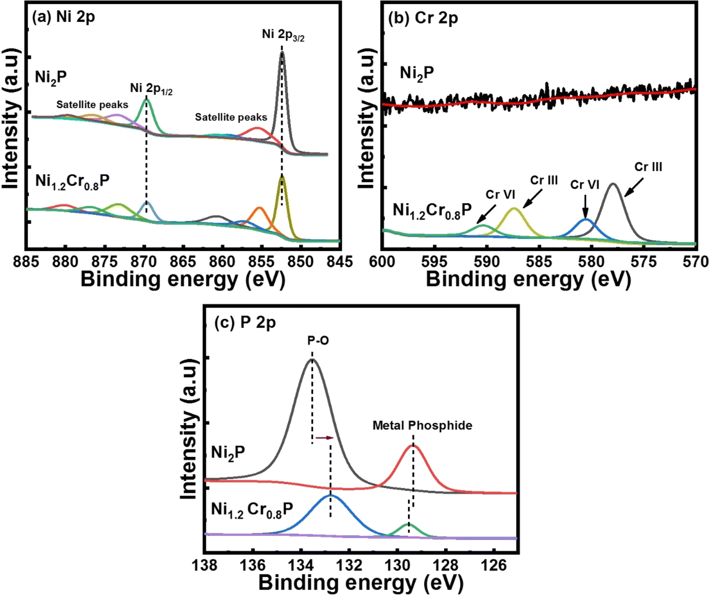 | ||
| Fig. 2 High-resolution core-level XPS spectra of (a) Ni 2p, (b) Cr 2p and (c) P 2p in Ni1.2Cr0.8P NRs. | ||
Investigation of MOR and HER activities
The electrocatalytic MOR and HER performances were measured using a typical three-electrode configuration with Ag/AgCl as a reference electrode and a graphite rod as the counter electrode (Φ = 6 mm). The electrocatalytic MOR activities of Ni2−xCrxP NCs (x = 0, 0.2, 0.4, 0.6 and 0.8) were evaluated in 1 M KOH/3 M MeOH electrolyte. The linear sweep voltammetry (LSV) curves in Fig. 3a show the catalytic activity of various electrocatalysts, including Ni2P, Ni1.8Cr0.2P, Ni1.6Cr0.4P, Ni1.4Cr0.6P and Ni1.2Cr0.8P, all of which exhibit significant activity. Interestingly, the Ni1.2Cr0.8P electrocatalyst showed excellent catalytic activity surpassing the other electrocatalysts, requiring overpotential values of 1.14, 1.29 and 1.43 V to achieve anodic current densities of 10, 50 and 100 mA cm−2, respectively. The electrocatalytic activity of Ni1.2Cr0.8P electrocatalysts was further evaluated in 1 M KOH electrolyte with different MeOH concentrations (Fig. S6†). A sharp increase in the anodic current can be clearly visible when the MeOH concentration was increased from 0.5 M to 3 M, indicating the favorable MOR electrocatalytic activity of Ni1.2Cr0.8P electrocatalysts. Moreover, the corresponding Tafel slope of Ni1.2Cr0.8P is evaluated to be 52 mV dec−1, whereas Ni1.4Cr0.6P, Ni1.6Cr0.4P, Ni1.8Cr0.2P and Ni2P show the Tafel slopes of 72, 76, 90 and 103 mV dec−1, respectively (Fig. 3b), demonstrating significant MOR kinetics on the electrocatalysts. Their long-term durability plays a crucial role in determining the viability of electrocatalysts for commercialization. The Ni1.2Cr0.8P electrocatalyst displayed a negligible potential fluctuation during a 20 h test, indicating its excellent MOR stability (Fig. 3c). The extent to which voltage fluctuations observed in our catalysts are considered negligible depends on the susceptibility of the measurements. In general, voltage fluctuations on the order of a few millivolts may be considered acceptable with a precise measurement set-up. Several pieces of evidence, for example Zhang et al.,52 demonstrated a similar voltage fluctuation of Ti/Ir0.8Nd0.2Ox electrocatalysts in alkaline as well as acidic electrolytes. Furthermore, Shanmugam et al.53 confirmed the robust HER stability of NiCoSeP nanostructured electrocatalysts with a negligible potential change. The long term stability test of Ru0.09Co2.91O4 nanoparticles reported by Nam et al.54 reveals a voltage fluctuation of ∼1 V in the initial 50 h of the stability test for chlorine evolution reaction. The HER electrocatalytic activities of the electrocatalysts were evaluated in 1 M KOH electrolyte (Fig. 3d). Remarkably, the Ni1.2Cr0.8P electrocatalyst outperformed all other electrocatalysts, exhibiting the lowest overpotential values of 72 mV, 206 mV and 282 mV to achieve a current density of 10, 50 and 100 mA cm−2. Furthermore, the Tafel slopes of all the electrocatalyst were evaluated, in which Ni1.2Cr0.8P showed a Tafel slope of 42 mV dec−1, whereas Ni1.4Cr0.6P, Ni1.6Cr0.4P, Ni1.8Cr0.2P and Ni2P displayed the Tafel slopes of 68 mV dec−1, 81 mV dec−1, 98 mV dec−1 and 112 mV dec−1, respectively (Fig. 3e), indicating that the electrocatalysts possess significant reaction kinetics for the HER. These results further suggest that the HER mechanism on the electrocatalyst follows the Volmer–Heyrovsky pathway.55 Moreover, the promising HER performance of Ni1.2Cr0.8P was further confirmed by its long-term durability test, demonstrating its stability for over 20 h (Fig. 3f). | ||
| Fig. 3 (a) MOR polarization curves and (b) corresponding Tafel plots of Ni1.2Cr0.8P, Ni1.4Cr0.6P, Ni1.6Cr0.4P, Ni1.8Cr0.2P and Ni2P. (c) Long-term MOR durability test of Ni1.2Cr0.8P for 20 h. (d) HER polarization curves and (e) corresponding Tafel plots of Ni1.2Cr0.8P, Ni1.4Cr0.6P, Ni1.6Cr0.4P, Ni1.8Cr0.2P and Ni2P. (f) Long-term HER durability test of Ni1.2Cr0.8P for 20 h. | ||
Electrochemical characterization of Ni2−xCrxP NCs
To gain deeper understanding of why the Ni1.2Cr0.8P electrocatalyst outperforms other electrocatalysts, the electrochemically active surface area (ECSA) and charge transfer kinetics were investigated. To verify the catalytically active sites, ECSAs were evaluated by cyclic voltammetry (CV) measurements (Fig. S7a–e†). The anodic and cathodic current density differences were plotted against the scan rate (Fig. S7f†) to determine the electrochemical double-layer capacitance (Cdl) of the Ni1.2Cr0.8P electrocatalyst as 0.361 mF cm−2, which is comparatively higher than that of Ni1.4Cr0.6P (0.298 mF cm−2), Ni1.6Cr0.4P (0.235 mF cm−2), Ni1.8Cr0.2P (0.167 mF cm−2) and Ni2P (0.121 mF cm−2). Additionally, the ECSA of Ni1.2Cr0.8P electrocatalysts was evaluated to be 9.025 cm2, higher than that of the other electrocatalysts (Fig. S7g†), indicating that the Ni1.2Cr0.8P electrocatalyst offers a larger number of catalytically active sites than the other electrocatalysts. Besides, the Nyquist plots of the electrochemical impedance spectra (EIS) in Fig. S8† revealed that the Ni1.2Cr0.8P electrocatalyst has the smallest semi-circle with a charge-transfer resistance (Rct) of ∼22 Ω, which is 25 times smaller than that of undoped Ni2P (∼550 Ω). These results imply that the Ni1.2Cr0.8P electrocatalyst exhibits the fastest charge-transfer kinetics, further enhancing the MOR and HER catalytic activities. Moreover, the significantly higher specific active surface area of 92.47 m2 g−1 for the Ni1.2Cr0.8P electrocatalyst, estimated using Brunauer–Emmett–Teller (BET) measurements, agrees well with the above results (Fig. S9a†).To further investigate the intrinsic activities of electrocatalysts towards the MOR, the mass activity (MA) and specific activity (SA) of all electrocatalysts were estimated using mass loading and ECSA normalized curves, respectively (Fig. S9b and c†). The Ni1.2Cr0.8P electrocatalyst exhibited a higher MA of 15 mA mg−1 compared to Ni1.4Cr0.6P (13.8 mA mg−1), Ni1.6Cr0.4P (11.3 mA mg−1), Ni1.8Cr0.2P (10.5 mA mg−1) and Ni2P (8.9 mA mg−1). In addition, the Ni1.2Cr0.8P electrocatalyst showed the highest SA of 9.2 mA cm−2, surpassing Ni1.4Cr0.6P (7.5 mA cm−2), Ni1.6Cr0.4P (6.9 mA cm−2), Ni1.8Cr0.2P (6.0 mA cm−2) and Ni2P (5.0 mA cm−2) (Fig. S9d†), indicating the superior catalytic activity of Ni1.2Cr0.8P electrocatalysts towards the MOR. The intrinsic activities of electrocatalysts towards the HER were further investigated in a similar way as shown in Fig. S10a–c.† The Ni1.2Cr0.8P electrocatalyst showed a higher MA of 40 mA mg−1 compared to Ni1.4Cr0.6P (30 mA mg−1), Ni1.6Cr0.4P (20 mA mg−1), Ni1.8Cr0.2P (18 mA mg−1) and Ni2P (12 mA mg−1). Furthermore, the Ni1.2Cr0.8P electrocatalyst displayed a SA of 0.5 mA cm−2, higher than that of Ni1.4Cr0.6P (0.4 mA cm−2), Ni1.6Cr0.4P (0.35 mA cm−2), Ni1.8Cr0.2P (0.3 mA cm−2) and Ni2P (0.2 mA cm−2) electrocatalysts as shown in Fig. S10c,† indicating the superior catalytic activity of the Ni1.2Cr0.8P electrocatalyst towards the HER. These collective measurements demonstrate that the Ni1.2Cr0.8P electrocatalyst exhibits promising electrocatalytic activity with good stability for both the MOR and the HER.
Theoretical calculations and identifying active sites for the MOR and HER
DFT calculations were also performed to better understand the origin of the excellent electrocatalytic activity of the MOR and HER after Cr doping in Ni2P. Since only fewer studies have been carried out on the MOR activity of Ni2P-based electrocatalysts, it becomes essential to better understand the underlying fundamental reasons for the high selectivity of the MOR to value-added formate rather than CO2 on both undoped and Cr-doped Ni2P electrocatalysts through DFT calculations. To achieve this, different structural models were constructed and investigated, including undoped Ni2P (111), Cr-doped Ni2P (111) (one Cr atom per unit cell), Cr-rich Ni2P (111) (3 atoms of Cr per unit cell), undoped Ni2P (300), Cr-doped Ni2P (300) (one Cr atom per unit cell) and Cr-rich Ni2P (300) (4 Cr atoms per unit cell) shown in Fig. S11.† The Gibbs free energy diagrams (ΔG) for the methanol oxidation process on Ni2P (111) and Cr-doped Ni2P (300) surfaces are shown in Fig. 4a. The details of the calculation process are provided in the ESI.† The dehydrogenation of *CH3OH to *OCH3 was identified as the potential rate determining step (RDS) for Ni2P (111) and Cr-doped Ni2P (111), while the dehydrogenation of *OCH3 to *OCH2 was found to be the RDS for Ni2P (300) and Cr-doped Ni2P (300) (Fig. 4a). The reaction barrier associated with the first RDS was computed to be 1.11 eV on the undoped Ni2P (111) surface, which decreased to 0.70 eV and 0.57 eV on the Cr-doped Ni2P (111) and Cr-rich Ni2P (111) surfaces, respectively. Similarly, the reaction barrier associated with the RDS was estimated to be 0.79 eV on the Ni2P (300) surface, which decreased to 0.71 eV on the Cr-doped Ni2P (300) surface and remained at ∼0.79 eV on the Cr-rich doped Ni2P (300) surface as shown in Fig. S12a.† This suggests that the MOR is expected to proceed much faster on the Cr-doped Ni2P (300) surface. The transition from (111) to (300) crystal orientation and the introduction of Cr as a dopant both have favorable effects on enhancing the MOR. Furthermore, we also find out that *HOOCH has the lowest Gibbs free energy reaction compared to other reaction intermediates, indicating the high selectivity of methanol conversion to value-added formate. | ||
| Fig. 4 Free energy diagrams: (a) Gibbs free energy diagrams of undoped Ni2P (111) and Cr-doped Ni2P (300) for the MOR. (b) Hydrogen adsorption free energy diagrams of undoped Ni2P (111) and Cr-doped Ni2P (300) for the HER. | ||
Typically, the HER is characterized by a sequence of three states involving an initial H+ and e−pair, an intermediate state with adsorbed H (H*), and the final product of 1/2H2. The activity of the HER process is primarily determined by the free energy value of adsorbed H (ΔGH*), which is considered to be a critical descriptor for HER activity.56 DFT calculations were performed to compute the ΔGH* values on undoped Ni2P (111) and (300) surfaces, as well as Cr-doped Ni2P and Cr-rich Ni2P (111) and (300) surfaces. The ΔGH* values are calculated as follows: −0.57 eV and −0.54 eV for undoped Ni2P (111) and (300) surfaces, respectively, while −0.68 eV and −0.59 eV for Cr-doped Ni2P (111) and Cr-rich doped Ni2P (111) surfaces, respectively, as shown in Fig. S12b.† Interestingly, these values are estimated to be −0.51 eV and −0.37 eV for Cr-doped Ni2P (300) and Cr-rich Ni2P (300) surfaces, respectively, as shown in Fig. 4b. The close-to-thermoneutral value of −0.37 eV for the Cr-rich doped Ni2P (300) surface compared to undoped Ni2P (111) and (300) surfaces reveals that Cr doping increases hydrogen adsorption and desorption, which is consistent with HER activity (Fig. 3d). All these findings together imply that Cr-induced crystal orientation to the (300) plane favors both the thermodynamics of the dehydrogenation process in the MOR and hydrogen adsorption in the HER, leading to enhanced electrocatalytic MOR and HER activities. In addition, from the observation of the PDOS of Ni atoms in Ni2P (111) and Ni2P Cr-doped (300) surfaces, as shown in Fig. S13,† the d-band centers are −1.35 (up) and −1.33 (down) and −1.12 (up) and −1.08 (down) eV, respectively. Based on d-band center theory, the higher d-band center means stronger adsorption energy between the surface and intermediates.56
This trend of the d-band center relative to the Fermi level agrees well with the adsorption energies of intermediates for the MOR (e.g., *HOCH3, *OCH3, *OCH2, etc.), in which stronger adsorption on the Cr-doped (300) surface is achieved than that on the Ni2P (111) surface. We, therefore, believe that the addition of the Cr dopant into Ni2P corresponds to the changes of surface catalytic activity.
Evaluation of Ni1.2Cr0.8P as a bifunctional electrocatalyst for OMeS and OWS
Inspired by the high MOR and HER electrocatalytic activities of the Ni1.2Cr0.8P electrocatalyst, we further evaluated its applicability as a bifunctional electrocatalyst (as a cathode and anode) for OMeS in a two-electrode system using 1.0 M KOH/3 M MeOH as the electrolyte. The LSV curves in Fig. 5a demonstrate the electrocatalytic activity of the Ni1.2Cr0.8P electrocatalyst towards OMeS and OWS in 1.0 M KOH/3 M MeOH and 1 M KOH, respectively. It is evident that the cell voltage significantly decreased when methanol oxidation is coupled with H2 production.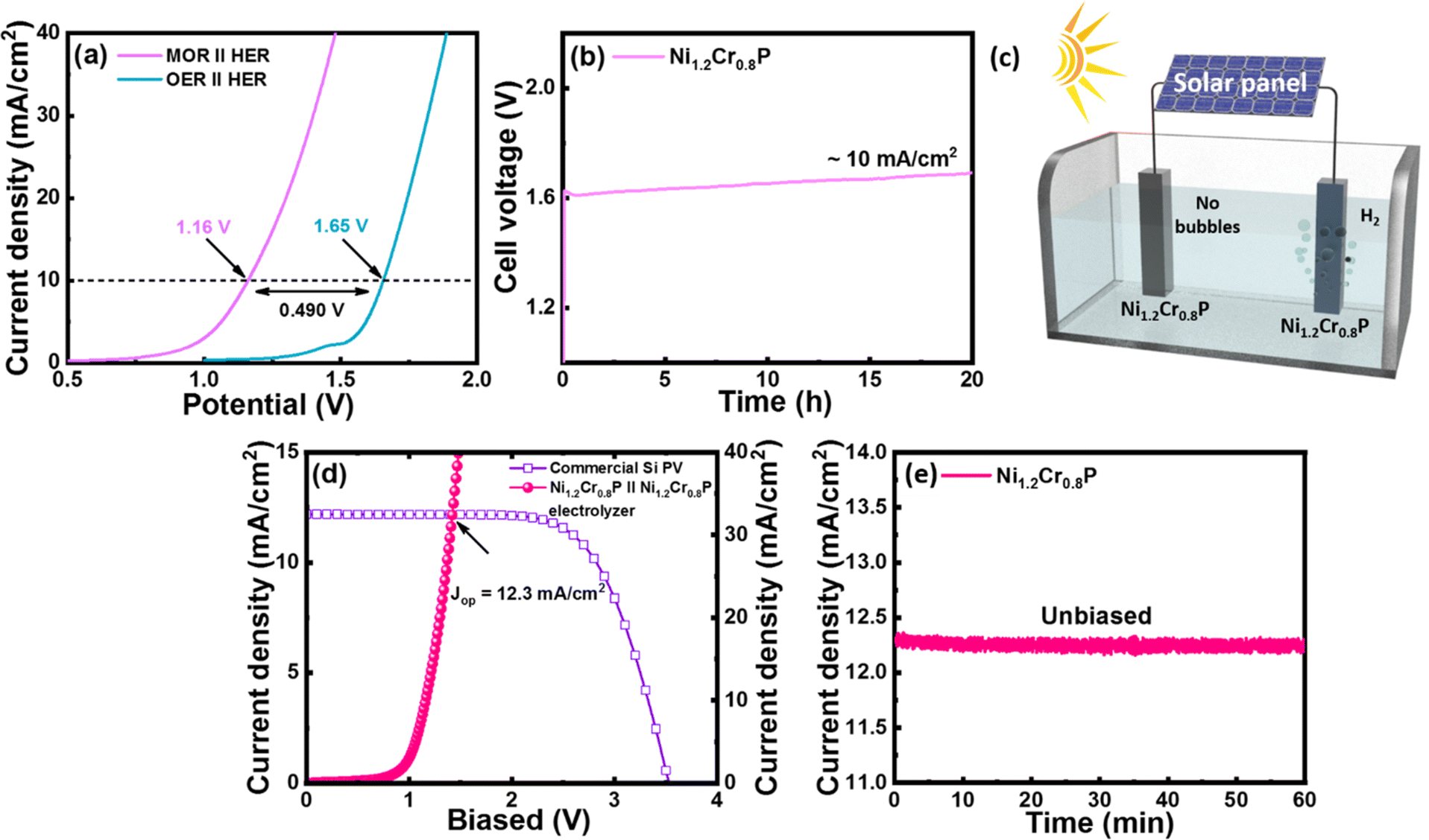 | ||
| Fig. 5 (a) Comparison of polarization curves for OMeS (MOR‖HER) in 1.0 M KOH/3 M MeOH and OWS (OER‖HER) in 1 M KOH using Ni1.2Cr0.8P electrocatalysts as both an anode and a cathode. (b) Long-term durability test of OMeS for 20 h. (c) Schematic representation of a solar-driven electrolysis cell. (d) Solar-to-hydrogen (STH) efficiency plot for the OMeS system (e) Unbiased water splitting photocurrent measured for 60 min in the OMeS system. | ||
Specifically, the Ni1.2Cr0.8P electrocatalyst requires a low cell voltage of 1.16 V to achieve a current density of 10 mA cm−2 for OMeS in 1.0 M KOH/3 M MeOH, which is lower than the cell voltage of 1.65 V required to achieve a current density of 10 mA cm−2 in 1 M KOH as represented in Fig. 5a. Furthermore, this OMeS system is durable for 20 hours at a current density of 10 mA cm−2 as shown in Fig. 5b. Importantly, H2 bubbles can be clearly observed on the Ni1.2Cr0.8P cathode surface, while no bubbles are observed on the Ni1.2Cr0.8P anode surface, indicating that the MOR is more preferable than the OER on the anode surface in the two-electrode system as shown in Fig. 5c.
To further identify the oxidation products, OMeS was performed in 1.0 M KOH/3 M MeOH at a current density of 10 mA cm−2 and a liquid sample was collected. The 1H NMR spectrum (Fig. S14†) confirmed the formation of value-added formate in OMeS. Furthermore, the amount of H2 generated experimentally at a cell voltage of ∼1.2 V is close to the theoretical calculation value (Fig. S15†) and the faradaic efficiency (FE) for the HER is calculated to be as high as ∼74%. The chronopotentiometry measurement performed to test the long-term stability of the Ni1.2Cr0.8P electrocatalyst in OMeS revealed no significant change in cell voltage (Fig. 5b). Post-electrolysis TEM images (Fig. S16†) and EDS elemental mapping (Fig. S17†) show no significant changes in the morphology and elemental distribution. The post-electrolysis XPS results also indicated slightly shifted binding energies of Ni 2p, Cr 2p and P 2p, suggesting alterations in the local chemical environment and chemical states of the Ni1.2Cr0.8P electrocatalyst during/after the electrochemical reactions. However, the core-level P 2p spectra show an increased peak intensity of the P–O peak, which could be attributed to the further oxidation of P species under alkaline conditions (Fig. S18†). These thorough post-electrolysis investigations prove the morphological and structural robustness of the Ni1.2Cr0.8P electrocatalyst, which is beneficial for rapid charge transfer during electrochemical processes, further improving its electrochemical activity and durability.57 This stability test reveals the significant promise of the Ni1.2Cr0.8P electrocatalyst for the MOR and HER, allowing us to generate value-added formate while producing H2.
To demonstrate the possible utilization of the Ni1.2Cr0.8P electrocatalyst in sustainable H2 production, a photovoltaic (PV)–OMeS system was built by integrating a commercial silicon PV device with an OMeS electrolyzer employing Ni1.2Cr0.8P as a bifunctional electrocatalyst (Fig. 5d and S17†). Under natural sunlight, continuous H2 evolution was observed at the cathode surface, whereas no bubble formation was seen at the anode surface, confirming methanol oxidation at the anode surface (Fig. S19†). The PV-OMeS system further demonstrated a photocurrent density of ∼12.3 mA cm−2 when integrated with a commercial silicon PV device as shown in Fig. 5d. Interestingly, the as-demonstrated PV-OMeS system sustained at ∼12.3 mA cm−2 photocurrent density for 60 min. under constant light illumination (Fig. 5e), illustrating the potential of the Ni1.2Cr0.8P electrocatalyst for efficient and sustainable H2 production.
Conclusions
In summary, we demonstrated the colloidal synthesis of Cr-dopant induced morphology transition in Ni2P nanocrystals using a simple one-pot heat up approach. These electrocatalysts displayed excellent bifunctional electrocatalytic activity for both the MOR and the HER under alkaline conditions. Notably, the Ni1.2Cr0.8P electrocatalyst exhibited a low working overpotential of 1.14 V to achieve a current density of 10 mA cm−2 for the MOR in 1 M KOH/3 M MeOH electrolyte, and a very low overpotential of 74 mV for the HER in 1 M KOH, respectively. Moreover, Ni1.2Cr0.8P was used as both the anode and the cathode in a two-electrode OMeS cell, requiring a cell voltage of 1.16 V to reach a current density of 10 mA cm−2, thus enabling energy-efficient H2 production by replacing the inactive OER with the MOR. DFT calculations revealed that the Cr-doped Ni2P (300) surface exhibited faster reaction kinetics for the MOR, with *HOOCH exhibiting the lowest free energy among other reaction intermediates, indicating selective methanol conversion to value-added formate. Moreover, Cr-rich doped Ni2P (300) enhanced the hydrogen adsorption and desorption for the HER, with a thermoneutral value of −0.37 eV. Encouraged by these promising results, we demonstrated a solar-driven approach using commercial Si PV integrated with an OMeS cell, achieving a stable photocurrent density of 12.3 mA cm−2. This work represents a significant step forward in designing efficient electrocatalysts for co-electrolysis systems, enabling selective oxidation reactions to produce value-added chemical products while facilitating sustainable H2 production.Conflicts of interest
The authors declare no conflict of interests.Acknowledgements
This work was supported by the Priority Research Centers Program through the National Research Foundation of Korea (NRF) funded by the Ministry of Education, Science and Technology (2018R1A6A1A03024334) and was supported by the National Research Foundation of Korea (NRF) grant funded by the Korea government (MSIT) (No. 2022R1A2C2007219). M. P. S. acknowledges the Australian Research Council (ARC) for the Discovery Early Career Researcher Award (DECRA) (DE210101565).References
- J. A. Turner, Sci., 2004, 305, 972–974 CrossRef CAS PubMed.
- T. Terlouw, C. Bauer, R. McKenna and M. Mazzoti, Energy Environ. Sci., 2022, 15, 3583–3602 RSC.
- M. A. Gaikwad, U. P. Suryawanshi, U. V. Ghorpade, J. S. Jang, M. P. Suryawanshi and J. H. Kim, Small, 2021, 18, 2105084 CrossRef PubMed.
- I. Roger, M. A. Shipman and M. D. Symes, Nat. Rev. Chem, 2017, 1, 1–13 CrossRef.
- Y. Wang, T. Zhou, K. Jiang, P. Da, Z. Peng, J. Tang, B. Kong, W.-B. Cai, Z. Yang and G. Zheng, Adv. Energy Mater., 2014, 4, 1400696 CrossRef.
- L. Dai, Q. Qin, X. Zhao, C. Xu, C. Hu, S. Mo, Y. O. Wang, S. Lin, Z. Tang and N. Zheng, ACS Cent. Sci., 2016, 2, 538–544 CrossRef CAS PubMed.
- M. A. Gaikwad, V. V. Burungale, D. B. Malavekar, U. V. Ghorpade, U. P. Suryawanshi, S. Jang, X. Guo, S. W. Shin, J.-S. Ha, M. P. Suryawanshi and J. H. Kim, Adv. Energy Mater., 2024, 2303730 CrossRef.
- Z. Pu, I. S. Amiinu, F. Gao, Z. Xu, C. Zhang, W. Li, G. Li and S. Mu, J. Power Sources, 2018, 401, 238–244 CrossRef CAS.
- X. Yu, R. B. Araujo, Z. Qiu, E. C. Santos, A. Anil, A. Cornell, L. G. M. Pettersson and M. Johnsson, Adv. Energy Mater., 2022, 12, 2103750 CrossRef CAS.
- Dr. S. Chen, Dr. J. Duan, A. Vasileff and S. Z. Qiao, Angew. Chem., 2016, 128, 3868–3872 CrossRef.
- X. Bao, M. Liu, Z. Wang, D. Dai, P. Wang, H. Cheng, Y. Liu, Z. Zheng, Y. Dai and B. Huang, ACS Catal., 2022, 12(3), 1919–1929 CrossRef CAS.
- J. Zheng, X. Chen, X. Zhong, S. Li, T. Liu, G. Zhuang, X. Li, S. Deng, D. Mei and J.-G. Wang, Adv. Funct. Mater., 2017, 27, 1704169 CrossRef.
- M. P Suryawanshi, U. V Ghorpade, C. Y. Toe, U. P. Suryawanshi, M. He, D. Zhang, J. S. Jang, S. W. Shin, J. H. Kim, X. Hao and R. Amal, Prog. Mater. Sci., 2023, 134, 101073 CrossRef.
- F. Schorn, J. L. Breuer, R. C. Samsun, T. Schnorbus, B. Heuser, R. Peters and D. Stolten, Adv. Appl. Energy, 2021, 3, 100050 CrossRef CAS.
- J.-P. Lange, Catal. Today, 2001, 64, 3–8 CrossRef CAS.
- S. Wang, Q. Mao, H. Ren, W. Wang, Z. Wang, Y. Xu, X. Li, L. Wang and H. Wang, ACS Nano, 2022, 16(2), 2978–2987 CrossRef CAS.
- J. Zhong, X. Yang, Z. Wu, B. Liang, Y. Huang and T. Zhang, Chem. Soc. Rev., 2020, 49, 1385–1413 RSC.
- Dr. J. Li, R. Wei, X. Wang, Y. Zuo, X. Han, J. Arbiol, J. Llorca, . Y. Yang, . A. Cabot and . C. Cui, Angew. Chem., Int. Ed., 2020, 59, 20826–20830 CrossRef PubMed.
- Q. Liu, L. Wu, S. Gülak, N. Rockstroh, R. Jackstell and M. Beller, Angew. Chem., Int. Ed., 2014, 53, 7085–7088 CrossRef CAS PubMed.
- J. Eppinger and K.-W. Huang, ACS Energy Lett., 2017, 2(1), 188–195 CrossRef CAS.
- M. Li, X. Deng, K. Xiang, Y. Liang, B. Zhao, J. Hao, J.-L. Luo and X.-Z. Fu, ChemSusChem, 2020, 13, 914–921 CrossRef CAS PubMed.
- F. Arshad, T. Haq, A. Khan, Y. Haik, I. Hussain and F. Sher, Energy Convers. Manage., 2022, 254, 115262 CrossRef CAS.
- J. Hao, J. Liu, D. Wu, M. Chen, Y. Liang, Q. Wang, L. Wang, X.-Z. Fu and J.-L. Luo, Appl. Catal., B, 2021, 281, 119510 CrossRef CAS.
- G. Ma, X. Zhang, G. Zhou and X. Wang, Chem. Eng. J., 2021, 411, 128292 CrossRef CAS.
- Y. Xu, M. Liu, M. Wang, T. Ren, K. Ren, Z. Wang, X. Li, L. Wang and H. Wang, Appl. Catal., B, 2022, 300, 120753 CrossRef CAS.
- F. Zhang, H. Meng, W. Zhang, M. Wang, J. Li and X. Wang, Int. J. Hydrogen Energy, 2019, 43, 3203–3215 CrossRef.
- M. Li, X. Deng, Y. Liang, K. Xiang, D. Wu, B. Zhao, H. Yang, J.-L. Luo and X.-Z. Fu, J. Energy Chem., 2020, 50, 314–323 CrossRef.
- K. Liu, Z. Ma, J. Li and X. Wang, Int. J. Hydrogen Energy, 2024, 51, 713–724 CrossRef CAS.
- X. Sun, P. Yang, S. Wang, J. Hun, P. Chen, H. Xing and W. Zhu, Int. J. Hydrogen Energy, 2022, 47, 28495–28504 CrossRef CAS.
- L. Li, W. Gao, K. Tang, M. Lei, B. Yao, W. Qi and D. Wen, Electrochim. Acta, 2021, 369, 137692 CrossRef CAS.
- M.-T. Chen, J.-J. Duan, J.-J. Feng, L.-P. Mei, Y. Jiao, L. Zhang, A.-J. Wang and J. Col, Int. Sci., 2022, 605, 888–896 CAS.
- Y. Liu, Y. Xing, X. Zheng, S. Xu, D. Li and D. Jiang, Appl. Surf. Sci., 2022, 600, 154099 CrossRef CAS.
- Y. Guo, X. Yang, X. Liu, X. Tong and N. Yang, Adv. Funct. Mater., 2022, 33, 2209134 CrossRef.
- F. Wang, Y. Han, C. S. Lim, Y. Lu, J. Wang, J. Xu, H. Chen, C. Zhang, M. Hong and X. Liu, Nature, 2010, 463, 1061–1065 CrossRef CAS PubMed.
- N. Ortiz and S. E. Skrabalak, Langmuir, 2014, 30(23), 6649–6659 CrossRef CAS PubMed.
- S.-I. Choi, S. Xie, M. Shao, J. H. Odell, N. Lu, H.-C. Peng, L. Protsailo, S. Guerrero, J. Park, X. Xia, J. Wang, M. J. Kim and Y. Xia, Nano Lett., 2013, 13, 3420–3425 CrossRef CAS PubMed.
- Y. Kang, X. Ye and C. B. Murray, Angew. Chem., 2010, 122, 6292–6295 CrossRef.
- K. Yin, Y. Chao, F. Lv, L. Tao, W. Zhang, S. Lu, M. Li, Q. Zhang, L. Gu, H. Li and S. Guo, J. Am. Chem. Soc., 2021, 143, 10822–10827 CrossRef CAS PubMed.
- B. Seo, D. S. Baek, Y. J. Sa and S. H. Joo, CrystEngComm, 2016, 18, 6083–6089 RSC.
- J. Liu, Z. Wang, J. David, J. Llorca, J. Li, X. Yu, A. Shavel, J. Arbiol, M. Meyns and A. Cabot, J. Mater. Chem. A, 2018, 6, 11453–11462 RSC.
- U. P. Suryawanshi, U. V. Ghorpade, D. M. Lee, M. He, S. W. Shin, P. V. Kumar, J. S. Jang, H. R. Jung, M. P. Suryawanshi and J. H. Kim, Chem. Mater., 2021, 33(1), 234–245 CrossRef CAS.
- H. Liang, A. N. Gandi, D. H. Anjum, X. Wang, U. Schwingenschlögl and H. N. Alshareef, Nano Lett., 2016, 16(12), 7718–7725 CrossRef CAS PubMed.
- B. You, N. Jiang, M. Sheng, M. W. Bhushan and Y. Sun, ACS Catal., 2016, 6(2), 714–721 CrossRef CAS.
- H. Wang, H. Zou, Y. Liu, Z. Liu, W. Sun, K. A. Lin, T. Li and S. Luo, Sci. Rep., 2021, 11, 21414 CrossRef CAS PubMed.
- E. V. Korotaev, M. M. Syrokvashin, I. Y. Filatova, A. V. Kalinkin and A. V. Sotnikov, Sci. Rep., 2021, 11, 18934 CrossRef CAS PubMed.
- N. Yao, P. Li, Z. Zhou, Y. Zhao, G. Cheng, S. Chen and W. Luo, Adv. Energy Mater., 2019, 9(41), 1902449 CrossRef CAS.
- U. P. Suryawanshi, U. V. Ghorpade, D. M. Lee, M. He, S. W. Shin, P. V. Kumar, J. S. Jung, H. R. Jung, M. P. Suryawanshi and J. H. Kim, Chem. Mater., 2021, 33(1), 234–245 CrossRef CAS.
- L. Zhang, Y. Qi, L. Sun, G. Chen, L. Wang, M. Zhang, D. Zeng, Y. Chen, X. Wang, K. Xu and F. Ma, Appl. Surf. Sci., 2020, 512, 145715 CrossRef CAS.
- L. Xiong, B. Wang, H. Cai, H. Hao, J. Li, T. Yang and S. Yang, Appl. Catal., B, 2021, 294, 120283 CrossRef.
- H. Liang, A. N. Gandi, D. H. Anjum, X. Wang, U. Schwingenschlögl and H. N. Alshareef, Nano Lett., 2016, 16(12), 7718–7725 CrossRef CAS PubMed.
- Y. Wu, X. Tao, Y. Qing, H. Xu, F. Yang, S. Luo, C. Tian, M. Liu and X. Lu, Adv. Mater., 2019, 31(15), 1900178 CrossRef PubMed.
- J. Hu, H. Xu, X. Feng, L. Lei, Y. He and X. Zhang, ChemElectroChem, 2021, 8(6), 1204–1210 CrossRef CAS.
- M. Maleki, A. S. Rouhaghdam, G. B. Darband, D. Han and S. Shanmugam, ACS Appl. Energy Mater., 2022, 5(3), 2937–2948 CrossRef CAS.
- W. I. Choi, S. Choi, M. Balamurugan, S. Park, K. H. Cho, H. Seo, H. Ha and K. T. Nam, ACS Omega, 2023, 8(38), 35034–35043 CrossRef CAS PubMed.
- H. Tan, B. Tang, Y. Lu, Q. Ji, L. Lv, H. Duan, N. Li, Y. Wang, S. Feng, Z. Li, C. Wang, F. Hu, Z. Sun and W. Yan, Nat. Commun., 2022, 13, 2024 CrossRef CAS PubMed.
- D.-Y. Kuo, E. Nishiwaki, R. A. Rivera-Maldonado and B. M. Cossairt, ACS Catal., 2023, 13, 287–295 CrossRef CAS.
- N. Dubouis and A. Grimaud, Chem. Sci., 2019, 10, 9165 RSC.
Footnote |
| † Electronic supplementary information (ESI) available. See DOI: https://doi.org/10.1039/d4ta01147c |
| This journal is © The Royal Society of Chemistry 2024 |