 Open Access Article
Polariton ring currents and circular dichroism of Mg-porphyrin in a chiral cavity†
Shichao
Sun
 ,
Bing
Gu
 and
Shaul
Mukamel
 *
*
Department of Chemistry and Department of Physics & Astronomy, University of California, Irvine, USA. E-mail: smukamel@uci.edu
First published on 3rd January 2022
Abstract
By placing Mg-porphyrin molecules in a chiral optical cavity, time reversal symmetry is broken, and polariton ring currents can be generated with linearly polarized light, resulting in a circular dichroism signal. Since the electronic state degeneracy in the molecule is lifted by the formation of chiral polaritons, this signal is one order of magnitude stronger than the bare molecule signal induced by circularly polarized light. Enantiomer-selective photochemical processes in chiral optical cavities is an intriguing future possibility.
Introduction
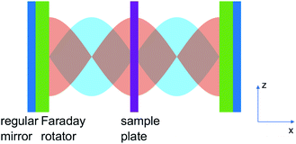
Optical cavities have recently emerged as a new means for manipulating photophysical and photochemical molecular processes.1–3 The vacuum electric field due to the zero-point energy of a confined optical cavity mode can modify the molecular potential energy landscape even in the absence of external driving fields. The cavity mode can be characterised by the qualify factor Q, defined as the ratio of the cavity frequency and resonance width. Larger Q implies higher quality and longer cavity photon lifetime. Substantial couplings can be induced between electronic or vibrational molecular transitions and the confined cavity mode. In the strong coupling regime whereby the light-matter coupling is stronger than the loss rate of the cavity mode and the molecular decoherence rate, the molecular degrees of freedom mix with the cavity photon to form hybrid light-matter states, known as polaritons. Molecular polaritons, which carry both characters of matter and light, have been reported for a plethora of systems, even for a single molecule.3–8 Experimental evidence suggesting that the strong coupling can alter the branching ratio of a chemical reaction,9 induce long-range energy transfer,4,5 enhance Raman scattering,7 and modify photochemical reaction rates10 has triggered extensive theoretical activities.10–30Chiral cavities refer to optical cavities with spatial, temporal or spatio-temporal symmetries broken.31 Here we focus on the chiral cavity whose mode profile depend on the circular polarization. They offer a new means for controlling photophysical properties of molecules. Such chiral optical cavity can be constructed by embedding the Faraday rotator32 in a Fabry–Perot cavity.31 Faraday rotator is a material with magneto-optical effect. With a longitudinal static magnetic field is applied on the Faraday rotator, the left and right circularly polarized light are shifted by different phases when transmitting through it. The phase of the circularly polarized standing wave formed in the cavity is shifted by the Faraday rotator. This can lead to an asymmetry in the spatial profiles of the left and right circularly polarized cavity mode, in contrast to non-chiral cavities where the spatial profile is independent of the polarization. By tuning the phase shift, it is possible to position the spatial envelope peak of the right circularly polarized wave at the node of the left circularly polarized wave. We can then create regions in the cavity where thin layers are sorely subjected to the left or right circularly polarized cavity mode, as shown in Fig. 1. Such chiral cavity where left and right circularly polarized cavity modes couples differently to the embedded molecules is highly promising for controlling the chiral photophysical properties of molecules and materials. A characteristic feature of chiral cavities is that it breaks the time reversal symmetry. Time reversal symmetry is a property where physical property is invariant under time reversal operation. For a cavity with regular mirrors, time reversal symmetry cannot be broken. At a given location, a time reversal operation will revert a circular polarization mode to the opposite circular polarization. With time reversal symmetry, an embedded molecule will effectively couple with a linearly polarization mode in a non-chiral cavity. Breaking this symmetry can lead to interesting effects such as light induced ring currents,33 magnetic circular dichroism44 and topological states.61
In this paper, we explore the effects of time reversal symmetry breaking on Mg-porphyrin molecules placed in a chiral cavity.
The first effect is an induced ring current in a cyclic conjugated molecule. In the absence of external perturbations, ring currents of opposite directions are equally likely, and no net current is produced. By breaking time reversal symmetry using either circularly polarized light33–36 or a static magnetic field,37–42 ring current in one direction is favored and a net ring current can be produced. The two methods have different features. The static magnetic field perturbs all states since it is not resonant with any excited state, whereas circularly polarized light can be tuned to be resonant with a selected state. Another difference is that circularly polarized light does not lift the degeneracy of excited states while a magnetic field does. In an achiral molecule with a Cn rotation axis where n > 2 pumped with circularly polarized pulse, the time-resolved circular dichroism (CD) signal involving doubly degenerate states with E character is usually weak since CD signals from a pair of doubly degenerate states cancel out.43 We refer to doubly degenerate states as E states in the following. The magnetic field, in contrast, removes the E states degeneracy and produces two relatively strong peaks with opposite sign in the magnetic circular dichroism (MCD) signal, known as  -term in MCD spectrum.43–45
Chiral optical cavities breaks the time-reversal symmetry through the vacuum field with local optical chirality. The cavity mode frequency can be tuned by changing the distance between mirrors to couple with selected molecular excited states. By placing the Mg-porphyrin molecules in a chiral optical cavity, a ring current can be created even by a linearly polarized light, in contrast to a bare molecule, which requires a circularly polarized light pulse to break the time reversal symmetry. Moreover, the cavity mode selectively couples with one of the degenerate pair of E states of a molecule possessing a rotation axis Cn (n > 2). This lifts the two fold degeneracy thus producing a stronger CD signal.
Hereafter, we explore the effects of chiral optical cavity on the polariton ring currents. It is well established computationally that a circular polarized light pulse can create a ring current in Mg-porphyrin.33 This is formed by the coherence of degenerate excited states with Eu irreducible representation of Mg-porphyrin and can be detected by time-resolved X-ray circular dichroism.46 Here, we show how to create a ring current by applying a linearly polarized pump pulse on a Mg-porphyrin molecule placed in a chiral optical cavity. Extending the work in ref. 46, we probe the polariton ring current by measuring the UV-visible circular dichroism signal following optical pump excitation. We further explore the enhancement of the CD signal in the chiral cavity by lifting the excited state degeneracy and the signatures of detuning and coupling strength of the chiral cavity. Finally, we compare the polariton CD with molecular MCD, and show that they share a similar mechanism of enhancing the CD signal.
Theory and methodology
As shown in Fig. 1, we place the molecules in the y–z plane, with the four N atoms lying along the y, z axes. The molecular geometry is optimized using DFT with the B3LYP functional47–50 and the 6-31g(d) basis set and Gaussian 16.51 The excited states are computed with time-dependent density functional theory in the Tamm–Dancoff approximation (TDA) using the Chronus Quantum code.52 Both DFT and TDA calculations employ the same density functional and basis set used in the geometry optimization. The energy and transition electric dipoles between the ground and excited states are listed in Table S1 in ESI.† The transition dipole moments between excited states are given in Table S2.†The molecular excited states |m1〉 and |m2〉 are degenerate with energy ℏω1 = 2.4481 eV, and have transition electric dipoles along z and −y respectively. We construct their linear combinations
 | (1) |
 | (2) |
The chiral cavity can be built with two Faraday mirrors placed in the yz plane (Fig. 1). Unlike ordinary (Fabry–Perot) cavities which contain two regular mirrors, a chiral cavity is formed with two parallel Faraday mirrors, where a Faraday rotator is placed on top of each regular mirror. A circularly-polarized light reflected by a regular mirror has the reverse circular polarization and propagation direction, thus forming a circularly polarized standing wave. In a cavity with regular mirrors, due to time reversal symmetry, the coexistence of standing wave modes with opposite circular polarization makes the cavity mode achiral. In a chiral cavity, the Faraday rotator rotates the polarization of the left/right circularly polarized standing wave differently, giving their spatial envelope a phase difference φ (see eqn (S3) in ESI†). For  where n = 0, 1, 2…, the peak of the spatial envelope of right circularly polarized wave lies at the node of the left circularly polarized wave, producing a plane dominated by a right circularly polarized wave (Fig. 1) where a Mg-porphyrin thin film is placed. The cavity-mode frequency is ℏωc = ℏω+ − δ, where δ is its detuning. The quantized circularly polarized standing wave can be written as
 | (3) |
 are the polarization vectors, a and a† are creation and annihilation operator of cavity mode respectively and
  is the vacuum electric field amplitude where V is the cavity volume and ε0 is vacuum permittivity.
  is the cavity Hamiltonian. The molecule/cavity interaction Hamiltonian is
 | (4) |
 | (5) |
 | (6) |
 is the coupling strength. For a plane with area A, N = nA, where n is the number of molecules per unit area. Thus the coupling strength
  where L is the distance between the cavity mirrors. The terms containing aμ+ and a†μ− in eqn (6) represent the polariton interaction, while aμ− and a†μ+ are counter-rotating terms.
The total Hamiltonian is H = Hmol ⊗ Ic + Hc ⊗ Imol + HI. The joint light-matter states |Mj, n〉 = |Mj〉 ⊗ |n〉 are given by direct products of molecular and cavity-photon number states. The polariton states denoted |Pα〉 (α = 0, 1, 2, 3…) are obtained by diagonalizing this Hamiltonian in the joint molecule–cavity space, where α runs over polariton states.
We use a left-circularly polarized pulse
 | (7) |
 to excite the molecule. We assume that the external laser fields couple directly to the molecules. We used the pulse amplitude E0 = 5.14 × 10⁷ V cm−1 (intensity I = 3.51 × 10¹² W cm−2) and Ω is resonant with |P0〉 to |P1〉 transition energy. σ is 0.072 6 fs (or 3.0 a.u.) (
 in energy domain) so that the pulse bandwidth selectively excites only the |P1〉, |P2〉 polariton states. Since the ground state energy in the chiral cavity is not very different from the vacuum (see Fig. 3), the ionization potential (IP) in the cavity, which can be approximated by the energy difference of the ground state of cation and neutral molecule, will be essentially the same as in the vacuum. With IP = 6.9 eV,33 the ionization rate is estimated with the tunneling ionization model53,54 as 9.7 × 10⁷ s−1, which is negligible. Thus, the ionization process is neglected. The polariton dynamics was calculated by solving the time dependent Schrödinger equation
 | (8) |
The polariton induced ring currents are monitored by the CD spectroscopy. The signal measured at frequency ω after the pump pulse is over is derived using time-dependent perturbation theory46
 | (9) |
 and Apr(ω) are the wave vector and the vector potential envelope of the probe pulse, respectively.
  is the Fourier transformed transition current density. ℏωe′′e′ = Ee′′ − Ee′ is the energy difference between two states. The ladder diagram representing eqn (9) is shown in Fig. 2. All CD spectra were simulated for N = 1 to exclude two-exciton states from different molecules in the double excitation manifold.
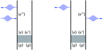 | ||
| Fig. 2 Ladder diagrams of the circular dichroism signal. The left and right diagrams correspond to first and second term in eqn (9) respectively. The gray zone is the pump pulse with either a linearly polarized pulse or circularly polarized pulse. After the pump pulse, the polariton is excited and described by density matrix ρee′. A CD measurement is done with circularly polarized pump pulse at a later time. | ||
For MCD, we apply B = 8 T magnetic field along the x axis and simulate the CD spectrum with linear response TDDFT55–57 using the same density functional and basis set used in TDA calculations.
Results and discussion
Ring current in the chiral polariton states
To study the chiral polaritons of Mg-porphyrin in a chiral cavity, we first identify the polariton states that carry a ring current. We set the detuning δ = 0 eV and the coupling strength g = 1.028 × 10⁻¹ V Å−1 (0.002 a.u.) where |gμg,m+| = 1.8 × 10⁻³ eV. With strong light-matter coupling, the ring-current-carrying bare molecular excited state (see eqn (1) and (5)) together with higher-lying excited states, hybridize with the cavity photon state |1〉 to form two polariton states |P1〉 and |P2〉 while the degenerate state
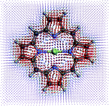
  remains intact, as shown in Fig. 3. The higher-lying excited states play an important role in the formation of polariton states because their large detuning is compensated by the stronger transition dipole moment. Similar effects were observed for a transition metal complex.30 Had we retained only the resonant |M±〉 states, the polariton states |P1/2〉 would be an equal mixture of states |M+, 0〉 and |G, 1〉 as in the Jaynes–Cummings model. However, |P2〉 is primarily |M+, 0〉 whereas |P1〉 is primarily |G, 1〉. The |P1〉 and |P2〉 states with Rabi splitting 27 meV carry an overall counterclockwise ring current as displayed in Fig. 5 with a spatial profile similar to the molecular ring current induced by a circularly polarized pump.33 The currents inside and outside the ring have the same direction.
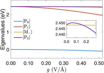 | ||
| Fig. 3 Polariton energy variation with g for detuning δ = 0. The splitting of |P1〉 and |P2〉 increase with g. The energy of |P2〉 is lower than |M−〉 for g > 0.16 V Å−1. | ||
In a chiral cavity, the molecule–cavity interaction has the contribution of μMj,G〈1|a†|0〉 in eqn (6). Through the counter-rotating term coupling (aμ− − a†μ+) between |G, 0〉 and |Mj, 1〉, the chiral cavity perturbs and creates a ring current in the polariton ground state |P0〉 as shown in Fig. 4. Even the ground state energy does not change much at g = 1.028 × 10⁻¹ V Å−1 in Fig. 3, the existence of ground state current shows the effect the counter-rotating term before even reaching the ultrastrong coupling regime, which is a direct evidence of time reversal symmetry breaking. The ground state current has more interesting features than the polariton excited state current. Apart from the overall counterclockwise current around the porphyrin, each pyrrole ring has its local ring current. The current around the Mg cation inside the porphyrin is in the opposite direction than the outside current.
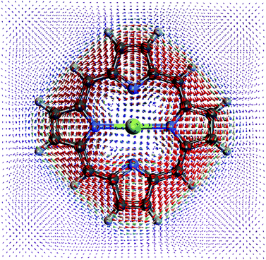 | ||
| Fig. 5 Current density profile of the |P1〉 polariton state. The ring current of |P2〉 is similar but stronger. | ||
Integrating the current density over the half plane shows that the current in the polariton ground state (1.6 × 10⁻⁸ A) is weaker than |P1〉 (7.9 × 10⁻⁶ A) and |P2〉 (7.4 × 10⁻⁵ A). The |P2〉 current is stronger since it has more contribution from |M+, 0〉 than |P1〉. The induced magnetic field on the Mg is 7.7 × 10⁻⁶ T for polariton ground state, 1.6 × 10⁻² T for |P1〉, and 1.5 × 10⁻¹ T for |P2〉.
Polariton ring-currents created by a circularly polarized pump pulse
The excited state polariton ring current is created by an external pump pulse. The time evolution of ground state and excited state populations for circularly polarized pulse eqn (7) is depicted in the top panel of Fig. 6. The applied pulse brings the ground state to the polariton state |P1〉. |P2〉 has a very small population since the oscillator strength from |P0〉 to |P2〉 is much weaker. The unperturbed excited state |M−〉 is not populated due to the selection rule. To probe the ring current, we have simulated the CD of the polariton states in UV-visible regime following a circularly polarized pulse shown in Fig. 8 top panel.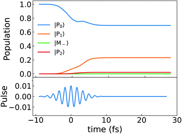 | ||
| Fig. 6 Top: population dynamics (eqn (8)) of the polariton states for a Mg-porphyrin in the chiral cavity excited by a circularly polarized pulse. Bottom: y component of the electric field of the pump pulse. | ||
For comparison, we present the same quantities for the bare (no cavity) Mg-porphyrin molecule in Fig. 7 and 8 bottom panel. The right circularly polarized light selectively excites the state |M+〉, which carries a ring current.
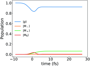 | ||
| Fig. 7 Population dynamics of the Mg-porphyrin molecule excited by a circularly polarized pulse same as Fig. 6. The molecular excited state 6 is slightly populated as well. | ||
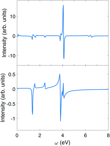 | ||
| Fig. 8 CD signals eqn (9) of polariton in the chiral cavity with δ = 0, g = 1.028 × 10⁻¹ V Å−1 (or 0.002 a.u.) (top), and no cavity (bottom). The CD measurement follows a circularly polarized pump pulse in both polariton and bare molecule. | ||
We first observe an order of magnitude enhanced polariton CD signal around 4.0 eV. In the CD signal without cavity, the peaks between 3.7 eV and 4.1 eV have those contributions: At 3.795 9 eV, the excitation is from |G〉 to |M3〉 has intensity  , and transition from |M3〉 to |G〉 with intensity
  . At 4.060 1 eV, the transition from |M9〉 to |G〉 with intensity
  . However, in polariton CD, the 3.7 to 4.1 eV regime is dominated by a group of much stronger peaks. We can assign the contributions of various polariton states by examining the numerator in the CD expression eqn (9). The strongest 4.1 eV peaks correspond to two pairs of transitions: (1) excitation from the ground state |P0〉 to the polariton states |P10〉, |P11〉, which mainly consist of −i|M8, 0〉 + |M9, 0〉 and i|M8, 0〉 + |M9, 0〉 respectively; (2) excitation from lower polariton state |P1〉 (mainly consist of |G, 1〉) to polariton state |P21〉 and |P23〉, which primarily consist of i|M8, 1〉 − |M9, 1〉 and −i|M8, 1〉 − |M9, 1〉 respectively. Note that the degenerate molecular states |M8〉 and |M9〉 with Eu irreducible representation have electric dipole along y and −z respectively (Table S1†). In order to explain the CD signal enhancement, we define degenerate molecular states
  . Their CD signal strengths of molecular systems are determined by
  and
and  (eqn (9)), which have the same magnitude but an opposite sign. Since the molecular states |MII+〉 and |MII−〉 are degenerate, their CD signals cancel out. For the polariton states |P10〉 and |P11〉, the CD signal strength jP0,P10 × jP10P0 and jP0P11 × jP11P0 have a similar magnitude but an opposite sign. Due to their coupling with the chiral cavity, states |P10〉 and |P11〉 are non degenerate. We thus see a strong positive peak and negative peak next to each other in the polariton spectrum around 4.1 eV. The cause of the strong CD signal from |P1〉 to the polariton states |P21〉 and |P23〉 is similar. Since |P1〉 carries a polariton ring current, the 4.1 eV peak can be viewed as partially ring current CD signal and partially ground state excitation signal.
To further confirm that the enhancement of CD is caused by the chiral cavity, we place the molecule in a non-chiral cavity with a linearly polarized standing wave  , where the polarization vector is
  . The polarization vectors e+, e− in the molecule–cavity interaction Hamiltonian (eqn (6)) are replaced by the linearly polarization vector eyz. The resulting CD signal shown in Fig. 9 has a similar magnitude to that of the bare molecule. The enhancement of CD signal (top panel of Fig. 8) is thus due to the chiral modes.
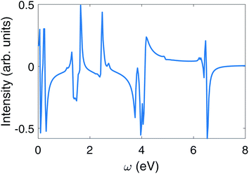 | ||
| Fig. 9 CD signal eqn (6) of polariton with δ = 0, g = 0.002 for Mg-porphyrin molecule in the linearly polarized cavity excited by circularly polarized pulse. | ||
The weaker peaks in the polariton CD signal in the top panel of Fig. 8 also contain signatures of polariton states. The 6.495 3 eV peak in the polariton CD is mainly the excitation from |P0〉 to |P21〉 (mostly i|M8, 1〉 − |M9, 1〉), with intensity  . Such peaks do not exist in the bare molecule CD signal shown in the lower panel of Fig. 8.
There are also some noticeable differences between the bare molecule and the polaritons in some groups of peaks. Without cavity, the 2.448 1 eV peak corresponds to the transition from the ground state to |M+〉 with intensity  . For polariton CD, the peak at 2.451 9 eV is the excitation from ground state |P0〉 to |M−〉 with intensity
  . The peaks at 2.453 4 eV and 2.426 3 eV represent excitations from ground state to upper and lower polariton states, with intensity
  and
and  respectively. Such excitations are not present in the bare molecule, due to the cancellation of signal of the degenerate states with Eu irreducible representation (see Table S1†).
The intensity of the group of peaks around 1.4 eV is similar for the bare molecule and polaritons. In the bare molecule, the negative 1.347 8 eV peak corresponds to the excitation from |M+〉 to excited state |M3〉 and its strength is determined by  (first term in eqn (9)). The positive 1.536 3 eV peak arises from the transition from |M+〉 to |M7〉, whose intensity is determined by
  . A similar excitation can be found in the polariton CD spectrum at 1.33 eV. The negative peak has two contributions: (1) the excitation from |P2〉 to |P5〉 (mostly |M3, 0〉) with intensity
  ; (2) the transition from |P5〉 to |P2〉 with intensity
  . The positive peak has two contributions: (1) |P5〉 to |P1〉, with intensity
  ; (2) transition from |P5〉 to |P1〉, with intensity
  .
.
Polariton ring currents created by a linearly polarized light
Unlike the bare molecules, the polariton ring currents can be induced by a linearly polarized light. The population dynamics is shown in Fig. 10. Following the pulse, the lower polariton state |P1〉 population increases significantly, while the unperturbed state |M−〉 only slightly increases since the transition dipole of ground state and lower polariton state μP0,P1 is much larger than that to the unperturbed state μP0,M−. The lower polariton state |P1〉 is dominated by |G, 1〉. Since the transition dipoles between ground state and higher excited states (e.g., excited state 4, 5, 8, 9 in Table S1†) are about 10 times higher than μG,M+ and μG,M−, the lower polariton state |P1〉 is mixed with these higher excited states through resonant interaction of the molecule–cavity coupling, for example 〈G, 1|μa†|M9, 0〉. The mixing of higher energy excited states with large detunings in the polariton states does not require counter-rotating terms, although there are extra contributions from them, for example, 〈M+, 0|μa|M9, 1〉. The transition dipole μG,P1 is thus much higher than μG,M−, which causes a population difference following the linear polarized pulse, thus creating a ring current. The CD spectrum of polariton excited by linearly polarized light is shown in the upper panel of Fig. 11. Enhancement of the CD spectrum in both linearly polarized light excitation (upper panel of Fig. 11) and in circularly polarized light excitation (upper panel of Fig. 8) originates from the excitations from |P0〉 and |P1〉 to higher excited states |P10〉, |P11〉, |P21〉, |P23〉. The degeneracy of |P10〉 and |P11〉 and of |P21〉 and |P23〉 are lifted by the chiral cavity mode.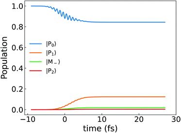 | ||
| Fig. 10 Population dynamics of polariton states created by a linearly polarized light pulse with δ = 0, g = 1.028 × 10⁻¹ V Å−1. | ||
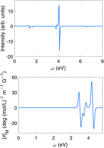 | ||
| Fig. 11 Upper panel: circular dichroism spectrum eqn (9) of polaritons with δ = 0, g = 1.028 × 10⁻¹ V Å−1 excited by linearly polarized pulse. Lower panel: magnetic circular dichroism of Mg-porphyrin molecule in the magnetic field of 8 T (or 3.403 5 × 10⁻⁵ a.u.). | ||
Signatures of detuning and coupling strength
The polariton state energies for zero detuning δ and different coupling strengths g are depicted in Fig. 3. In the weak coupling region (g < 1.6 × 10⁻¹ V Å−1), state |M−〉 is higher than |P1〉 and lower than |P2〉. For g > 1.6 × 10⁻¹ V Å−1, |M−〉 is higher than |P2〉.In Fig. 12, we vary the coupling g from 2.056 × 10⁻¹ V Å−1 to 5.142 × 10⁻¹ V Å−1 (or from 0.004 to 0.010 a.u.) holding the detuning δ = 0, and use a circularly polarized light pulse to initiate the dynamics.
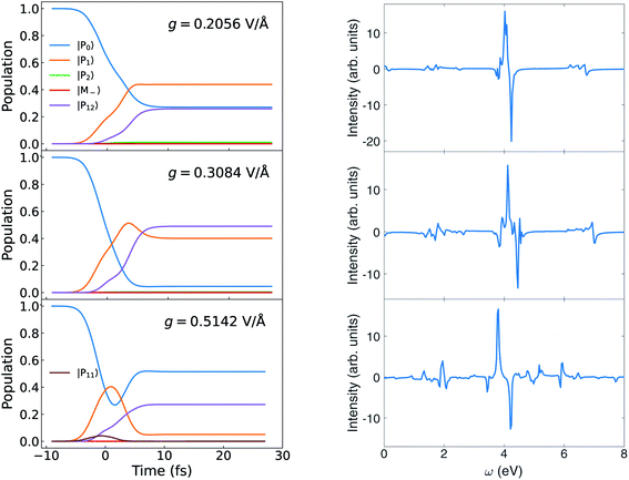 | ||
| Fig. 12 Left: Population dynamics for different g at δ = 0. Right: Circular dichroism signal eqn (9) for different g at δ = 0. | ||
Comparing Fig. 6 with the left panel of Fig. 12, we find that the population of the polariton state |P12〉 dominated by |G, 2〉 increases with coupling strength. As g is increased to 5.142 V Å−1, the population of |P12〉 (dominated by |G, 2〉) is much higher than the lower polariton state |P1〉 (dominated by |G, 1〉) after the pulse.
The variation of the polariton state energies with detuning is depicted in Fig. 13 for a fixed coupling strength g = 1.028 × 10⁻¹ V Å−1. The population evolution and the CD spectra are displayed in Fig. 14. For δ < 0, the lower polariton state |P1〉 is dominated by |M+, 0〉 while the upper polariton |P2〉 is dominated by |G, 1〉. For δ > 0, |P1〉 is dominated by |G, 1〉 and |P2〉 is dominated by |M+, 0〉. Since the polariton state dominated by |G, 1〉 can mix with higher excited states through μG,Mj, and increase the polariton transition dipole, these states can be highly populated by the circularly polarized pulse. This explains why the |P1〉 population increases for δ < 0, while |P2〉 increase for δ > 0. A similar trend can be found in Fig. 15 for the coupling strength g = 3.084 × 10⁻¹ V Å−1 (or 0.006 a.u.). Due to the larger coupling strength g in Fig. 15, the population has some two photon mode mixed in compared with Fig. 14.
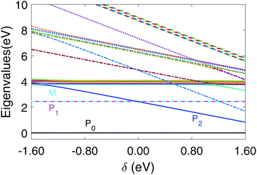 | ||
| Fig. 13 Polariton energy variation with detuning for coupling strength g = 1.028 × 10⁻¹ V Å−1. We mark |P0〉, |P1〉, |P2〉, |M−〉 with color. The legend of other polariton states are given in Fig. S1 in ESI.† | ||
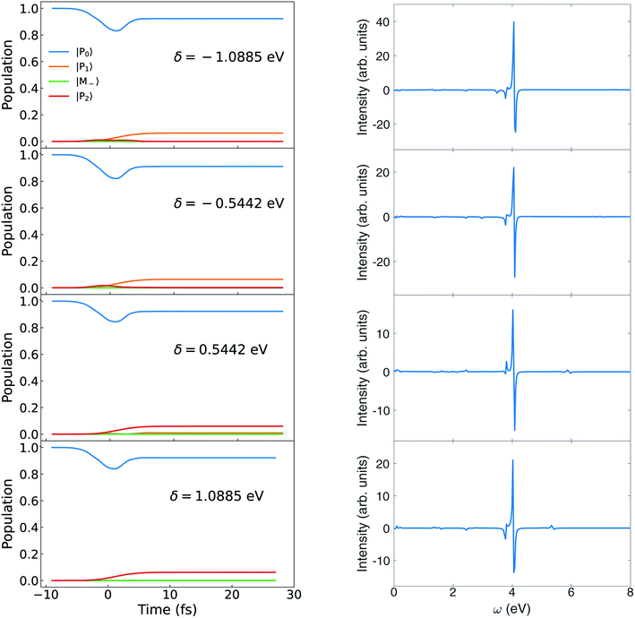 | ||
| Fig. 14 Left: Population dynamics for different δ at g = 0.102 8 V Å−1. Right: Circular dichroism signal eqn (9) for different δ at g = 0.102 8 V Å−1. | ||
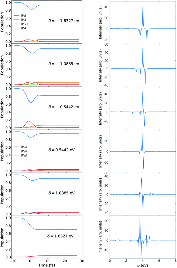 | ||
| Fig. 15 Left: Population dynamics for different δ at g = 0.308 4 V Å−1. Right: CD spectra eqn (9) for different δ at g = 0.308 4 V Å−1. | ||
Since the ring current in the polariton states dominated by |M+, 0〉 is strong, the cavity detuning δ can be adjusted to promote the polariton state dominated by |M+, 0〉 as in Fig. 14 and 15.
Comparison of polariton CD with MCD signals
It is instructive to compare the polariton CD signal with the bare molecule MCD, since both magnetic field and chiral optical cavities lift the excited state degeneracy. The excited states in the presence of magnetic fields are listed in table S2† in ESI.† Since MCD is simulated at the TDDFT level while chiral polaritons use the TDA, there are a small difference in energy. The peaks involving excited states of Eu irreducible representation can be assigned by comparing the upper and lower panel of Fig. 11. The strongest pair of peaks around 4.2 eV in MCD signal is the excitation from ground state to states 12, 13. While the strongest peaks at 4 eV in CD signal of Mg-porphyrin in chiral cavity is caused by the excitation from ground state to states |P10〉, |P11〉 which are dominated by |M8, 0〉, |M9, 0〉. By analyzing the molecular orbital contribution, states 12, 13 in TDDFT are equivalent to states 8, 9 in TDA. Thus the strongest peak of the molecule in the chiral cavity and in the magnetic field have a similar origin, i.e., breaking of degeneracy in excited states with Eu irreducible representation. The degeneracy is broken in the magnetic field by orbital Zeeman effect, since the angular momentum along the C4 rotation axis of the molecule is opposite in the degenerate Eu excited states. In the chiral cavity, the degeneracy is broken since the cavity mode is only coupled with one excited state in that pair of Eu degenerate states and leaving the other state unperturbed. This results in a pair of peaks with opposite sign.Similarly, a pair of weak MCD peaks at 2.38 eV originate from excited states 1, 2, while the peaks in polariton CD around 2.4 eV are from |P1〉, |P2〉 and |M−〉. These are also caused by the degeneracy breaking of states with Eu irreducible representation.
Summary
Chiral cavities open up numerous opportunities to for controlling photophysical properties of molecules. By exploring the effects of a chiral cavity on the ring current in Mg-porphyrin, we showed that the CD signal can be enhanced. We found a ring current in both ground state and polariton excited states made with chiral cavity. A strong polariton ring current can be created in the Mg-porphyrin in a chiral cavity by either a circularly polarized pulse or a linearly polarized light pulse. Due to cavity-induced coupling of the molecular ground state to higher excited state, the excitation from the ground state to the |P1〉 polariton state is stronger than to the unperturbed molecular state |M−〉. As a result, even a linearly polarized light can selectively excite the polariton state and create a strong ring current.This can be detected by a circular dichroism measurement after the pump pulse. The chiral cavity breaks the degeneracy of excited states with the Eu irreducible representation in cyclic conjugated molecules, resulting in pairs of peaks with opposite sign, which makes the polaritonic CD signal one order of magnitude stronger than in the bare molecule pumped with circularly polarized pulse. These results clearly demonstrate the utility of chiral cavities to manipulate photochemical processes of molecules. Future extensions of this study include incorporating the vibronic coupling,58–60 cavity leakage, and many-molecule collective dark states29 into the model. The chiral cavity-induced time reversal symmetry breaking may also be employed to create topological states.61
Data availability
All study data are included in the article and/or ESI.†Author contributions
S. M. supervised the project. B. G. and S. S. conceived the project. B. G. implemented the code for polaritonic dynamics. S. S. performed the electronic structure calculations, polariton and spectroscopy simulations. All authors contributed to the analysis and interpretation of the results, and wrote the manuscript.Conflicts of interest
There are no conflicts to declare.Acknowledgements
The support of the National Science Foundation through Grant No. CHE-1953045 is gratefully acknowledged. S. M. was supported by the U.S. Department of Energy, Office of Science, Office of Basic Energy Sciences under award DE-SC0022134.References
- F. Herrera and J. Owrutsky, Molecular Polaritons for Controlling Chemistry with Quantum Optics, J. Chem. Phys., 2020, 152, 100902 CrossRef CAS PubMed.
- D. Sidler, C. Schäfer, M. Ruggenthaler and A. Rubio, Polaritonic Chemistry: Collective Strong Coupling Implies Strong Local Modification of Chemical Properties, J. Phys. Chem. Lett., 2020, 508–516 Search PubMed.
- T. W. Ebbesen, Hybrid Light–Matter States in a Molecular and Material Science Perspective, Acc. Chem. Res., 2016, 49, 2403–2412 CrossRef CAS PubMed.
- X. Zhong, T. Chervy, S. Wang, J. George, A. Thomas, J. A. Hutchison, E. Devaux, C. Genet and T. W. Ebbesen, Non-Radiative Energy Transfer Mediated by Hybrid Light-Matter States, Angew. Chem., 2016, 128, 6310–6314 CrossRef.
- X. Zhong, T. Chervy, L. Zhang, A. Thomas, J. George, C. Genet, J. A. Hutchison and T. W. Ebbesen, Energy Transfer between Spatially Separated Entangled Molecules, Angew. Chem., Int. Ed., 2017, 56, 9034–9038 CrossRef CAS PubMed.
- J. George, A. Shalabney, J. A. Hutchison, C. Genet and T. W. Ebbesen, Liquid-Phase Vibrational Strong Coupling, J. Phys. Chem. Lett., 2015, 6, 1027–1031 CrossRef CAS PubMed.
- A. Shalabney, J. George, J. Hutchison, G. Pupillo, C. Genet and T. W. Ebbesen, Coherent Coupling of Molecular Resonators with a Microcavity Mode, Nat. Commun., 2015, 6, 5981 CrossRef CAS PubMed.
- F. Benz, M. K. Schmidt, A. Dreismann, R. Chikkaraddy, Y. Zhang, A. Demetriadou, C. Carnegie, H. Ohadi, B. de Nijs, R. Esteban, J. Aizpurua and J. J. Baumberg, Single-Molecule Optomechanics in “Picocavities”, Science, 2016, 354, 726–729 CrossRef CAS PubMed.
- A. Thomas, L. Lethuillier-Karl, K. Nagarajan, R. M. A. Vergauwe, J. George, T. Chervy, A. Shalabney, E. Devaux, C. Genet, J. Moran and T. W. Ebbesen, Tilting a Ground-State Reactivity Landscape by Vibrational Strong Coupling, Science, 2019, 363, 615–619 CrossRef CAS PubMed.
- J. A. Hutchison, T. Schwartz, C. Genet, E. Devaux and T. W. Ebbesen, Modifying Chemical Landscapes by Coupling to Vacuum Fields, Angew. Chem., Int. Ed., 2012, 51, 1592–1596 CrossRef CAS PubMed.
- C. Schäfer, M. Ruggenthaler, H. Appel and A. Rubio, Modification of Excitation and Charge Transfer in Cavity Quantum-Electrodynamical Chemistry, Proc. Natl. Acad. Sci. U. S. A., 2019, 116, 4883–4892 CrossRef PubMed.
- J. Galego, F. J. Garcia-Vidal and J. Feist, Cavity-Induced Modifications of Molecular Structure in the Strong-Coupling Regime, Phys. Rev. X, 2015, 5, 041022 Search PubMed.
- J. Flick, N. Rivera and P. Narang, Strong Light-Matter Coupling in Quantum Chemistry and Quantum Photonics, Nanophotonics, 2018, 7, 1479–1501 CAS.
- K. E. Dorfman and S. Mukamel, Multidimensional Photon Correlation Spectroscopy of Cavity Polaritons, Proc. Natl. Acad. Sci. U. S. A., 2018, 115, 1451–1456 CrossRef CAS PubMed.
- F. Herrera and F. C. Spano, Cavity-Controlled Chemistry in Molecular Ensembles, Phys. Rev. Lett., 2016, 116, 238301 CrossRef PubMed.
- D. M. Coles, N. Somaschi, P. Michetti, C. Clark, P. G. Lagoudakis, P. G. Savvidis and D. G. Lidzey, Polariton-Mediated Energy Transfer between Organic Dyes in a Strongly Coupled Optical Microcavity, Nat. Mater., 2014, 13, 712–719 CrossRef CAS PubMed.
- A. Frisk Kockum, A. Miranowicz, S. De Liberato, S. Savasta and F. Nori, Ultrastrong Coupling between Light and Matter, Nat. Rev. Phys., 2019, 1, 19–40 CrossRef.
- P. Vasa and C. Lienau, Strong Light–Matter Interaction in Quantum Emitter/Metal Hybrid Nanostructures, ACS Photonics, 2018, 5, 2–23 CrossRef CAS.
- M. Hertzog, M. Wang, J. Mony and K. Börjesson, Strong Light–Matter Interactions: A New Direction within Chemistry, Chem. Soc. Rev., 2019, 48, 937–961 RSC.
- J. Flick, M. Ruggenthaler, H. Appel and A. Rubio, Atoms and Molecules in Cavities, from Weak to Strong Coupling in Quantum-Electrodynamics (QED) Chemistry, Proc. Natl. Acad. Sci. U. S. A., 2017, 114, 3026–3034 CrossRef CAS PubMed.
- T. Schwartz, J. A. Hutchison, J. Léonard, C. Genet, S. Haacke and T. W. Ebbesen, Polariton Dynamics under Strong Light–Molecule Coupling, ChemPhysChem, 2013, 14, 125–131 CrossRef CAS PubMed.
- F. Herrera and F. C. Spano, Dark Vibronic Polaritons and the Spectroscopy of Organic Microcavities, Phys. Rev. Lett., 2017, 118, 223601 CrossRef PubMed.
- L. A. Martínez-Martínez, M. Du, F. Ribeiro, S. Kéna-Cohen and J. Yuen-Zhou, Polariton-Assisted Singlet Fission in Acene Aggregates, J. Phys. Chem. Lett., 2018, 9, 1951–1957 CrossRef PubMed.
- D. Sanvitto and S. Kéna-Cohen, The Road towards Polaritonic Devices, Nat. Mater., 2016, 15, 1061–1073 CrossRef CAS PubMed.
- A. Mandal and P. Huo, Investigating New Reactivities Enabled by Polariton Photochemistry, J. Phys. Chem. Lett., 2019, 10, 5519–5529 CrossRef CAS PubMed.
- K. Bennett, M. Kowalewski and S. Mukamel, Novel Photochemistry of Molecular Polaritons in Optical Cavities, Faraday Discuss., 2016, 194, 259–282 RSC.
- B. Gu and S. Mukamel, Manipulating Nonadiabatic Conical Intersection Dynamics by Optical Cavities, Chem. Sci., 2020, 11, 1290–1298 RSC.
- B. Gu and S. Mukamel, Optical-Cavity Manipulation of Conical Intersections and Singlet Fission in Pentacene Dimers, J. Phys. Chem. Lett., 2021, 12, 2052–2056 CrossRef CAS PubMed.
- B. Gu and S. Mukamel, Cooperative Conical Intersection Dynamics of Two Pyrazine Molecules in an Optical Cavity, J. Phys. Chem. Lett., 2020, 11, 5555–5562 CrossRef CAS PubMed.
- B. Gu, S. M. Cavaletto, D. R. Nascimento, M. Khalil, N. Govind and S. Mukamel, Manipulating Valence and Core Electronic Excitations of a Transition-Metal Complex Using UV/Vis and X-Ray Cavities, Chem. Sci., 2021, 8088–8095 RSC.
- H. Hübener, U. De Giovannini, C. Schäfer, J. Andberger, M. Ruggenthaler, J. Faist and A. Rubio, Engineering quantum materials with chiral optical cavities, Nat. Mater., 2021, 20, 438–442 CrossRef PubMed.
- Z. Nelson, L. Delage-Laurin, M. D. Peeks and T. M. Swager, Large Faraday Rotation in Optical-Quality Phthalocyanine and Porphyrin Thin Films, J. Am. Chem. Soc., 2021, 143, 7096–7103 CrossRef CAS PubMed , PMID: 33905654..
- I. Barth, J. Manz, Y. Shigeta and K. Yagi, Unidirectional Electronic Ring Current Driven by a Few Cycle Circularly Polarized Laser Pulse: Quantum Model Simulations for Mg- porphyrin, J. Am. Chem. Soc., 2006, 128, 7043–7049 CrossRef CAS PubMed , PMID: 16719485..
- I. Barth and J. Manz, Periodic Electron Circulation Induced by Circularly Polarized Laser Pulses: Quantum Model Simulations for Mg Porphyrin, Angew. Chem., Int. Ed., 2006, 45, 2962–2965 CrossRef CAS PubMed.
- I. Barth and J. Manz, Electric Ring Currents in Atomic Orbitals and Magnetic Fields Induced by Short Intense Circularly Polarized π Laser Pulses, Phys. Rev. A: At., Mol., Opt. Phys., 2007, 75, 012510 CrossRef.
- J. J. Rodriguez and S. Mukamel, Probing Ring Currents in Mg-Porphyrins by Pump–Probe Spectroscopy, J. Phys. Chem. A, 2012, 116, 11095–11100 CrossRef CAS PubMed , PMID:22 881200..
- P. Lazzeretti, Ring Currents, Prog. Nucl. Magn. Reson. Spectrosc., 2000, 36, 1–88 CrossRef CAS.
- J. Jusélius and D. Sundholm, The aromatic character of magnesium porphyrins, J. Org. Chem., 2000, 65, 5233–5237 CrossRef PubMed.
- E. Steiner and P. W. Fowler, Patterns of Ring Currents in Conjugated Molecules: A Few-Electron Model Based on Orbital Contributions, J. Phys. Chem. A, 2001, 105, 9553–9562 CrossRef CAS.
- G. Merino, T. Heine and G. Seifert, The Induced Magnetic Field in Cyclic Molecules, Chem.–Eur. J., 2004, 10, 4367–4371 CrossRef CAS PubMed.
- E. Steiner, A. Soncini and P. W. Fowler, Ring currents in the porphyrins: π shielding, delocalisation pathways and the central cation, Org. Biomol. Chem., 2005, 3, 4053–4059 RSC.
- T. Heine, C. Corminboeuf and G. Seifert, The Magnetic Shielding Function of Molecules and Pi-Electron Delocalization, Chem. Rev., 2005, 105, 3889–3910 CrossRef CAS PubMed , PMID: 16218570..
- L. D. Barron, Molecular light scattering and optical activity, Cambridge University Press, 2009 Search PubMed.
- S. B. Piepho and P. N. SchatzGroup Theory in Spectroscopy: with Applications to Magnetic Circular Dichroism, Wiley-Interscience, 1983, vol. 1 Search PubMed.
- W. R. Mason, Magnetic Circular Dichroism Spectroscopy, John Wiley & Sons, 2007 Search PubMed.
- Y. Nam, J. R. Rouxel, J. Y. Lee and S. Mukamel, Monitoring aromatic ring-currents in Mg-porphyrin by time-resolved circular dichroism, Phys. Chem. Chem. Phys., 2020, 22, 26605–26613 RSC.
- A. D. Becke, Density-Functional Exchange-Energy Approximation with Correct Asymptotic Behavior, Phys. Rev. A: At., Mol., Opt. Phys., 1988, 38, 3098 CrossRef CAS PubMed.
- A. D. Becke, Density-Functional Thermochemistry. III. The Role of Exact Exchange, J. Chem. Phys., 1993, 98, 5648 CrossRef CAS.
- C. Lee, W. Yang and R. G. Parr, Development of the Colle-Salvetti Correlation-Energy Formula into a Functional of the Electron Density, Phys. Rev. B: Condens. Matter Mater. Phys., 1988, 37, 785 CrossRef CAS PubMed.
- B. Miehlich, A. Savin, H. Stoll and H. Preuss, Results Obtained with the Correlation Energy Density Functionals of Becke and Lee, Yang and Parr, Chem. Phys. Lett., 1989, 157, 200–206 CrossRef CAS.
- M. J. Frisch, et al., Gaussian 16 Revision A.03, Gaussian Inc., Wallingford CT, 2016 Search PubMed.
- D. B. Williams-Young, A. Petrone, S. Sun, T. F. Stetina, P. Lestrange, C. E. Hoyer, D. R. Nascimento, L. Koulias, A. Wildman, J. Kasper, J. J. Goings, F. Ding, A. E. DePrince III, E. F. Valeev and X. Li, The Chronus Quantum Software Package, Wiley Interdiscip. Rev.: Comput. Mol. Sci., 2019, e1436 Search PubMed.
- A. D. Bandrauk, E.-W. S. Sedik and C. F. Matta, Effect of absolute laser phase on reaction paths in laser-induced chemical reactions, J. Chem. Phys., 2004, 121, 7764–7775 CrossRef CAS PubMed.
- P. B. Corkum, N. H. Burnett and F. Brunel, Above-threshold ionization in the long-wavelength limit, Phys. Rev. Lett., 1989, 62, 1259–1262 CrossRef CAS PubMed.
- S. Sun, D. Williams-Young and X. Li, An Ab Initio Linear Response Method for Computing Magnetic Circular Dichroism Spectra with Nonperturbative Treatment of Magnetic Field, J. Chem. Theory Comput., 2019, 15, 3162–3169 CrossRef CAS PubMed , PMID: 30933558..
- S. Sun, R. Beck, D. B. Williams-Young and X. Li, Simulating Magnetic Circular Dichroism Spectra with Real-Time Time-Dependent Density Functional Theory in Gauge Including Atomic Orbitals, J. Chem. Theory Comput., 2019, 15, 6824–6831 CrossRef CAS PubMed.
- S. Sun and X. Li, Relativistic Effects in Magnetic Circular Dichroism: Restricted Magnetic Balance and Temperature Dependence, J. Chem. Theory Comput., 2020, 16, 4533–4542 CrossRef CAS PubMed.
- K. R. Nandipati and O. Vendrell, On the generation of electronic ring currents under vibronic coupling effects, J. Chem. Phys., 2020, 153, 224–308 CrossRef PubMed.
- K. Schwennicke and J. Yuen-Zhou, Optical Activity from the Exciton Aharonov–Bohm Effect: A Floquet Engineering Approach, J. Phys. Chem. C, 2020, 124, 4206–4214 CrossRef CAS.
- H. Mineo, S. Lin and Y. Fujimura, Vibrational effects on UV/Vis laser-driven π-electron ring currents in aromatic ring molecules, Chem. Phys., 2014, 442, 103–110 CrossRef CAS.
- J. Yuen-Zhou, S. K. Saikin, N. Y. Yao and A. Aspuru-Guzik, Topologically Protected Excitons in Porphyrin Thin Films, Nat. Mater., 2014, 13, 1026–1032 CrossRef CAS PubMed.
Footnote |
| † Electronic supplementary information (ESI) available. See DOI: 10.1039/d1sc04341b |
| This journal is © The Royal Society of Chemistry 2022 |

