
 Open Access Article
 This Open Access Article is licensed under a Creative Commons Attribution-Non Commercial 3.0 Unported Licence
A bioinspired molybdenum–copper molecular catalyst for CO2 electroreduction†
Ahmed
Mouchfiq
a,
Tanya K.
Todorova
 a,
Subal
Dey
ab,
Marc
Fontecave
*a and
Victor
Mougel
*b
a,
Subal
Dey
ab,
Marc
Fontecave
*a and
Victor
Mougel
*b
aLaboratoire de Chimie des Processus Biologiques, UMR 8229 CNRS, Collège de France, Sorbonne Universitè, 11 Place Marcelin Berthelot, 75231 Paris Cedex 05, France. E-mail: marc.fontecave@college-de-france.fr
bDepartment of Chemistry and Applied Biosciences, ETH Zürich, Vladimir Prelog Weg 1, CH-8093 Zürich, Switzerland. E-mail: mougel@inorg.chem.ethz.ch
First published on 18th May 2020
Abstract
Non-noble metal molecular catalysts mediating the electrocatalytic reduction of carbon dioxide are still scarce. This work reports the electrochemical reduction of CO2 to formate catalyzed by the bimetallic complex [(bdt)MoVI(O)S2CuICN]2− (bdt = benzenedithiolate), a mimic of the active site of the Mo–Cu carbon monoxide dehydrogenase enzyme (CODH2). Infrared spectroelectrochemical (IR-SEC) studies coupled with density functional theory (DFT) computations revealed that the complex is only a pre-catalyst, the active catalyst being generated upon reduction in the presence of CO2. We found that the two-electron reduction of [(bdt)MoVI(O)S2CuICN]2− triggers the transfer of the oxo moiety to CO2 forming CO32− and the complex [(bdt)MoIVS2CuICN]2− and that a further one-electron reduction is needed to generate the active catalyst. Its protonation yields a reactive MoVH hydride intermediate which reacts with CO2 to produce formate. These findings are particularly relevant to the design of catalysts from metal oxo precursors.
Introduction
The development of efficient and selective catalysts for the electrochemical reduction of carbon dioxide is a key step to the sustainable production of carbon-based chemicals. Molecular catalysts mediating the two-electron/two-proton reduction of CO2 to carbon monoxide (CO) or formic acid (HCOOH) with high activity and selectivity have been identified.1–3 Their molecular nature enables providing key structural and mechanistic information to rationally design more complex heterogeneous catalysts.4–13 However, efficient molecular catalysts for CO2 reduction based on non-noble metals are still scarce.2,3 Among them, Ni-cyclams,14,15 Co phthalocyanine and Fe-porphyrins,16,17 have been discovered decades ago and only a few new members were recently reported, namely Mn(bpy)(CO)3Br,18 Fe-quaterpyridine,19 Fe4N(CO)12![[thin space (1/6-em)]](https://www.rsc.org/images/entities/char_2009.gif) 20 and Co diphosphine complexes.21,22 Interestingly, the great majority of these catalysts perform CO2 reduction to CO, and only very few, such as CoCp(diphosphine)21 and Fe4N(CO)1223 complexes generate formic acid as the major product.
20 and Co diphosphine complexes.21,22 Interestingly, the great majority of these catalysts perform CO2 reduction to CO, and only very few, such as CoCp(diphosphine)21 and Fe4N(CO)1223 complexes generate formic acid as the major product.
Enzymatic active sites constitute a great source of inspiration to expand this family of non-noble metal catalysts.24 Metal complexes replicating features of the active sites of metalloenzymes promoting CO2 transformation can be conceived in a so-called bioinspired approach. In that context, we had synthesized a series of dithiolene ligands mimicking the molybdopterin cofactor (MPT, shown in Fig. 1) in formate dehydrogenases (FDH) enzymes chelating the metal ion (Mo, W) in a bis(dithiolene) complex with its two sulfur atoms.25–29 One of the corresponding Mo complexes was shown to be the first example of a FDH mimic displaying catalytic activity for the conversion of CO2 into formic acid under photochemical conditions.25 The Ni analogue with the same dithiolene ligand also proved active for CO2 electroreduction to formic acid, showing high faradaic yields.30,31 These complexes, in which the Ni ion is coordinated by S atoms exclusively, are also reminiscent of the Ni active site of the Ni–Fe CO-dehydrogenase (CODH1), catalyzing the CO2-to-CO interconversion.32
 | ||
| Fig. 1 Active site of CODH2 from O. carboxidovorans (left), molybdopterin (MPT, centre) and structure of [(bdt)Mo(O)S2CuCN]2−, complex 1 (right) (MoCu–CODH backbone is highlighted in red in complex 1). | ||
Herein, we report the investigation of the electrocatalytic properties of a complex mimicking the active site of the second class of CO-dehydrogenase (CODH2) (Fig. 1). As opposed to CODH1 which functions reversibly, CODH2 has so far been shown to catalyze only CO oxidation to CO2 and not the reverse reaction, but reasons for this irreversibility are still unclear.24 Structural characterization of CODH2 from Oligotropha carboxidovorans has revealed a heterobimetallic Mo–Cu active site in which the two ions are bridged by a sulfide ion, the Mo ion also being coordinated by the MPT ligand and an oxo/hydroxo moiety (Fig. 1).33 This metal cofactor has led to the synthesis of a number of biomimetic Mo–Cu complexes, but none of them had been reported to show catalytic activity for CO2 reduction.34–38
In this work, we have performed in-depth investigations of the CO2 electroreduction catalytic activity of one of these complexes,38 [(bdt)MoVI(O)S2CuICN]2−, 1, (bdt = benzenedithiolate), in which Mo and Cu ions are connected by two μ2-sulfide ligands and the MPT ligand is mimicked by the bdt ligand chelating the Mo ion. While mimicking the structure of CODH2 active site, complex 1 reproduces the function of FDH, catalyzing CO2 reduction with a high selectivity for formate production. We demonstrate, using infrared spectroelectrochemical (IR-SEC) studies coupled with density functional theory (DFT) calculations that complex 1 is only a pre-catalyst, the active catalyst being formed after reduction and deoxygenation in the presence of CO2.
Results
Synthesis and characterization of [(bdt)MoVI(O)S2CuICN]2−, (1)
Complex 1 was synthesized following an adapted synthetic procedure from Tatsumi et al.38 and present identical NMR, UV-visible and FTIR spectroscopic signatures to previously reported ones (Fig. S1–S3†). However, the cyclic voltammogram (CV) at 50 mV s−1 of 1 under strict anaerobic conditions in argon-saturated CH3CN using tetrabutylammonium hexafluorophosphate (TBAPF6) supporting electrolyte and glassy carbon (GC) working electrode differed significantly from that published in ref. 38. While the latter exhibited two quasi-reversible waves at E1/2 = −2.02 V and −1.23 V vs. Ag/AgNO3 both originally assigned to one-electron Mo-based redox processes, we only observed a single quasi-reversible process at E1/2 = −2.02 V vs. Ag/AgNO3, (or −2.07 V vs. Fc/Fc+; unless stated otherwise, all potentials in the text below are vs. Fc/Fc+) (Fig. S4 and S5†). In our hands, we noticed the appearance upon exposure of the electrochemical cell containing complex 1 to air of an additional process at −1.22 V vs. Fc/Fc+ (corresponding to the wave at −1.23 V vs. Ag/AgNO338) (Fig. S4†). This CV change proved reversible, as witnessed by the disappearance of this signal after 30 min degassing of the solution with Ar, while the signal at −2.07 V remained unchanged. Therefore, we assigned this signal to O2 reduction and argue that the previously reported CV38 reflected a contamination of the electrochemical cell with air (Fig. S4†).
Determination of the number of electrons associated to the redox process at E1/2 = −2.07 V (Fig. S6 and S7†) by using chronoamperometry in a stationary regime at a carbon microelectrode shows that this process corresponds to a two-electron reduction of complex 1. We tentatively assigned it to a MoVI/MoIV process according to eqn (1).
| [(bdt)Mo(O)S2CuCN]2− + 2e− = [(bdt)Mo(O)S2CuCN]4− | (1) |
Finally, the peak current displayed a linear relation to the square root of the scan rate indicating that the active species are molecular in nature and that they function in a diffusion-controlled regime (Fig. S8†).
Cyclic voltammetry of complex 1 in the presence of CO2 and proton sources
The electroreduction of CO2 by complex 1 in the absence of a proton source was examined by cyclic voltammetry. Fig. 2 shows the CVs of complex 1 in dry argon- and CO2-saturated CH3CN on a GC electrode between −1.52 and −2.62 V. In the presence of CO2, the redox process at E1/2 = −2.07 V became irreversible and slightly increased in current density, and a catalytic wave appeared at an onset potential of roughly −2.4 V. The irreversibility and current increase of the signal at −2.07 V was also observed when cycling only down to −2.22 V, before the catalytic wave (inset, Fig. 2). | ||
| Fig. 2 Cyclic voltammograms of complex 1 under Ar (blue) and CO2 applying potentials from −1.52 V to −2.22 V vs. Fc/Fc+ (red, inset) and from −1.52 V to −2.62 V vs. Fc/Fc+ (black). 1 mM solution in dry CH3CN containing 0.1 M TBAPF6 electrolyte; GC working electrode; The scan rate was 50 mV s−1; the second scan is shown. | ||
Further purging the electrochemical cell with argon restored the reversible redox process associated to 1 at −2.07 V, indicating that complex 1 did not decompose in these conditions (Fig. S9†). No products were detected over a 1 hour electrolysis at −2.17 V, confirming the absence of catalytic activity of the complex at that potential. These data suggest a non-catalytic irreversible reaction of reduced complex 1 with CO2 leading to the formation of the active catalyst. We assigned the slight increase of activity mainly to the increase of concentration of the complex occurring during the CO2 purging process causing partial evaporation of the solvent.
The effect of proton sources on promoting CO2 reduction was then investigated. Recording CVs of complex 1 under CO2 in the presence of 0.1 M H2O (green line), 0.1 M TFE (trifluoroethanol, black line) or 0.1 M PhOH (phenol, purple) as proton sources allowed identifying TFE as the most effective to increase the current density of the catalytic process (Fig. 3).The concentration of 0.1 M TFE was found to be optimal, while concentrations greater than 0.2 M resulted in a loss of current density (Fig. S10†).
 | ||
| Fig. 3 Cyclic voltammograms of 1 mM complex 1 with 0.1 M TBAPF6 in dry CH3CN on a GC electrode under Ar (blue), CO2 (red), CO2 with 0.1 M TFE (black), CO2 with 0.1 M H2O (green) and CO2 with 0.1 M PhOH (purple). The scan rate was 50 mV s−1; the second scan is shown. | ||
Catalytic electroreduction of CO2 studied by controlled potential electrolysis
Controlled potential electrolysis (CPE) was carried out in CO2-saturated CH3CN on a GC electrode at −2.62 V in the presence of 0.1 M of TFE. The current density remained stable over the 1 h experiment (Fig. S11†). Product analysis of the headspace by gas chromatography revealed the presence of H2 and CO as the only gaseous products while ion-exchange liquid chromatography demonstrated the presence of formic acid. Quantification of these products (Table 1) indicated that the major reaction product was formate (FY = 69%), while CO (FY = 8%) and H2 (FY = 19%) accounted for the rest of the passed charge (total FY = 96%) for an overall turnover number (TON) of 4. A control experiment was carried out under an Ar atmosphere and did not show any formation of CO2 reduction products, the only detected product being H2.| E (V) | Catalyst | FY CO (%) | FY H2 (%) | FY HCOO− (%) | Total FY (%) | TONb |
|---|---|---|---|---|---|---|
| a 0.1 M TBAPF6 and 0.1 M TFE in 5 mL CO2-saturated CH3CN. b See ESI for details of turnover number (TON) calculation. c The low total FY is a consequence from the very low overall current, rendering background current (faradaic and kinetic/induced background currents) non-negligible. d TON after 2 h in brackets. | ||||||
| −2.62 | 1 (0.5 mM) | 8 | 19 | 69 | 96 | 2.8 (4.0)d |
| −2.37 | 1 (0.5 mM) | 4 | 21 | 74 | 99 | 1.6 |
| −2.62 | No catalyst | 4 | 11 | 0 | 14c | — |
The product distribution showed only a minor dependence on the applied potential. When CPE was carried out at a significantly more anodic potential (−2.37 V), FY for formate slightly increased up to 74%, while FY for CO decreased and FY for H2 remained almost unaffected (Table 1 and Fig. S11†). Control experiment without catalyst showed very low current density and no formate formation (Table 1 and Fig. S12†).
The molecular origin of the catalytically active species was assessed by several control experiments. First, a rinse test was carried out. After 1 hour CPE in the presence of complex 1 under standard catalytic conditions (CO2-saturated CH3CN with 0.1 M TBAPF6 and 0.1 M TFE), the electrode was separated from the electrolyte and then assayed for a second CPE using a fresh electrolyte solution in the absence of complex 1. As shown in Fig. S13,† the current density during the following CPE at −2.62 V was very low, as compared to that observed in the first CPE run, and analysis of the solution after one hour did not show any formation of CO2 reduction products. Second, no electrodeposited species were observed in electrocatalytic conditions, as shown by the absence of dissolution processes in post-electrolysis CV studies (Fig. S14†) and by the unchanged energy-dispersive X-ray spectra and scanning electron microscopy images of the electrode (Fig. S15–S17†) before and after electrolysis. This suggests that the catalytic activity originates from the soluble molecular species.
The importance of the bimetallic nature of the catalyst was illustrated in a comparative study with the mononuclear bis-bdt Mo complex, [MoIVO(bdt)2][Et4N]2, used as a model of the Mo subunit of complex 1. The CPE of [MoIVO(bdt)2][Et4N]2 at −2.62 V in CO2-saturated CH3CN with 0.1 M TBAPF6 and 0.1 M TFE did not show any CO2 reduction products (Fig. S18†).
Infrared spectroelectrochemical studies
In order to gain further insights into the CO2 reduction reaction mechanism, we investigated the behaviour of complex 1 in the presence of CO2via an infrared spectroelectrochemistry (IR-SEC) technique (Fig. 4).39,40 At resting potential, the IR stretch corresponding to the νCN mode was observed at 2124 cm−1 in both Ar and CO2 atmosphere, confirming that complex 1 did not react with CO2. At −2.24(11) V, the νCN mode shifted to 2081 cm−1, in agreement with an increased π backdonation to the CN− ligand upon reduction. Under a CO2 atmosphere at −2.24(11) V the same νCN stretch was observed, together with new stretches at 2150 and 2187 cm−1, indicating the formation of two new complexes presenting a significant change in the geometry of the Cu site. In addition, the appearance of new intense IR bands at 1678 and 1640 cm−1, characteristic of CO32− ions, implied that reduced complex 1 reacted with CO2via oxo-transfer to produce CO32− in solution. The complete disappearance of the signal for initial complex 1 at 2124 cm−1 highlights the considerably faster kinetics for the complex reduction in presence of CO2. Finally, the appearance of a new stretch at 1875 cm−1 suggested the formation of a Mo–H species.41 While this stretch was observed in the absence of a proton source, we hypothesize that protons might derive from the acetonitrile solvent. This was further confirmed by the disappearance of this stretch when deuterated acetonitrile was used as a solvent (together with that of the νCN stretch at 2187 cm−1, likely belonging to the same hydride species, Fig. S19†). | ||
| Fig. 4 IR-SEC of complex 1 in dry CH3CN with 0.1 M TBAPF6 at resting potential under Ar (green), CO2 (blue), and at −2.24(11) V vs. Fc/Fc+ under Ar (black) and CO2 (red). LabOMak IR-SEC cell equipped with Pt grid for working and counter electrodes and CE and Ag pseudo-reference electrode. | ||
Computational investigations of the CO2 reduction
DFT computations were performed to explore the CO2 reduction mechanism by 1 and to further elaborate the assignments of the spectroscopic features discussed above.![[double bond, length as m-dash]](https://www.rsc.org/images/entities/char_e001.gif) O group and the computed reaction free energy for the generation of complex 2a is exergonic by 4.5 kcal mol−1. Then, after binding a CO2 molecule 2a generates the pre-catalyst 3 (ΔG = −0.6 kcal mol−1) upon an irreversible transfer of the oxo group to form CO32− (Fig. 6). Complex 3 has a triplet ground state (the corresponding singlet state is 18.8 kcal mol−1 higher in energy), with Mo ion in a tetrahedral geometry.
O group and the computed reaction free energy for the generation of complex 2a is exergonic by 4.5 kcal mol−1. Then, after binding a CO2 molecule 2a generates the pre-catalyst 3 (ΔG = −0.6 kcal mol−1) upon an irreversible transfer of the oxo group to form CO32− (Fig. 6). Complex 3 has a triplet ground state (the corresponding singlet state is 18.8 kcal mol−1 higher in energy), with Mo ion in a tetrahedral geometry.
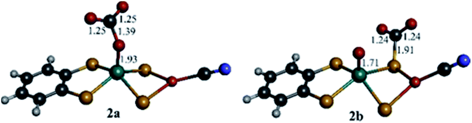 | ||
| Fig. 5 DFT optimized structures (B3LYP-D3/def2-TZVPD) of CO2 bound to complex 1red on oxo (2a) and on μ2-S (2b). Bond distances are given in Å. Mo is green, Cu is orange, S is yellow, O is red, N is blue, C is grey and H is white. | ||
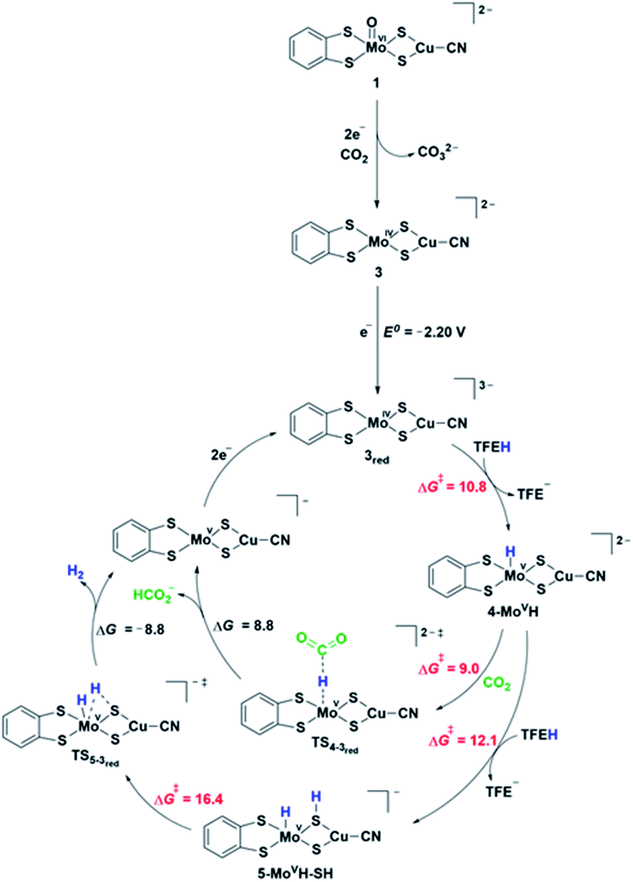 | ||
| Fig. 6 Proposed reaction mechanisms of CO2 reduction to formate and hydrogen by complex 3 obtained from the pre-catalyst 1. The relative Gibbs free energies (ΔG, kcal mol−1) and transition state barriers (ΔG#, kcal mol−1) are given relative to the preceding intermediate. The standard one-electron reduction potential (E0, V) is given vs. Fc/Fc+. Note that the added electron in complex 3red resides on the S3p orbitals of the ligands. | ||
DFT mechanistic pathways
Electrochemical studies suggest that catalysis requires additional electron(s). Fig. 6 shows the proposed pathways of CO2 reduction toward formate and hydrogen, involving a further one-electron reduction of 3 leading to 3red complex in a doublet ground state. The associated computed redox potential (E0 = −2.20 V) is in good agreement with the experimental onset of −2.40 V. The added electron resides on the S3p orbitals of the ligands exclusively, thus preserving the oxidation state of MoIV (Fig. S24b†). Further one-electron reduction of 3red is computed to occur at prohibitive redox potential and, as such, the plausible pathways involving 2-electron reduction of 3 have not been considered. The 3red complex is protonated by a TFE molecule most favorably at the Mo center (computed TS barrier of 10.8 kcal mol−1), giving rise to a Mo hydride species, 4-MoVH (Fig. S25†). Alternative protonation of the two different S atom types, i.e., metal bridging S and S from dithiolene, is +4.1 and +16.6 kcal mol−1, respectively, higher in energy. Formate is formed via a direct CO2 attack on 4-MoVH through a transition state TS4-3red with a free energy of activation of 9 kcal mol−1. Direct hydride transfer to form [MoV⋯HCO2−] complex is followed by a release of HCOO− and regeneration of 3red upon two-electron reduction. Alternatively, the 4-MoVH intermediate can accept a second proton from the acid source to form 5-MoVH-SH (ΔG# = 12.1 kcal mol−1). The protonation occurs on a bridging S atom, resulting in a S–H bond syn to the Mo–H bond. The computed TS barrier for hydrogen formation amounts to 16.4 kcal mol−1. The release of hydrogen (ΔG = −8.8 kcal mol−1) is followed by a two-electron reduction to regenerate the active species 3red. In contrast, a direct attack of TFE on the Mo–H bond to form MoH2 adduct has a significantly higher transition state barrier of 28.7 kcal mol−1 and is hence ruled out as an operating H2 pathway.IR frequencies by DFT
The reaction mechanism in Fig. 6 is further corroborated by comparison of computed characteristic vibrational frequencies of complex 1 and some of the key intermediates in the catalytic cycle to the experimental IR-SEC vibrations (Tables S3 and S4†). The experimental νCN stretches at 2081 cm−1, 2150 cm−1 and 2187 cm−1 observed upon reduction of complex 1 in a CO2 atmosphere are in good agreement with the computed values at 2059, 2128, and 2135 cm−1 of the reduced complexes 1red, 3 and 4-MoVH. Moreover, the calculated Mo–H stretching mode at 1858 cm−1 strongly suggests that the measured band at 1874 cm−1 can be attributed to the hydride complex 4-MoVH formed in the presence of a proton source, which is a key intermediate for the product formation.Discussion and conclusions
The main goal of this work was to evaluate the electrocatalytic activity in CO2 reduction of the heterobimetallic complex [(bdt)MoVI(O)S2CuICN]2−, 1, which is inspired by the active site of the CODH2 enzyme. We found that complex 1 was catalytically active and shows a good selectivity for formate, formed with an overpotential of ca. 800 mV. Such high overpotentials have been often observed for the few molecular catalysts catalyzing the reduction of carbon dioxide to formate.1,42Combined electrochemical analysis, IR-SEC data, DFT computations and catalytic activity studies identified that complex 1 is only a pre-catalyst. Its two-electron reduction triggers the irreversible transfer of the oxo group on Mo to a CO2 molecule to afford one carbonate equivalent and the tetrahedral Mo(IV) complex 3. The mechanism for the oxo transfer observed here differs significantly from oxo-transfer mechanisms observed with molybdoenzymes and synthetic analogues,43 where the oxo transfer is a redox process involving the reduction of a dioxo Mo(VI) complex to a monooxo Mo(VI) species. In the present case, the monooxo Mo(VI) complex 1 has only a weak basic character and the 2-electron reduction of the Mo center allows lowering its Lewis acidity and sufficiently enhancing the basicity of the oxo group to induce its transfer to CO2. The resulting complex, 3, can be further reduced by one electron to generate the active catalyst 3red, which is showing strong electron-donating properties at the Mo center provided by the metal-bridging S ligands. This allows for the formation of reactive MoVH hydride intermediates, which can react with CO2 to produce formate. The rather large overpotential observed with this catalyst can be explained by the highly cathodic potential required to transfer an electron on the S3p, necessary to generate a hard Mo center able to react with TFE and form such MoVH hydride intermediates. Furthermore, the higher transition state barrier for hydrogen formation than the barrier for formate production of these Mo hydride species is in agreement with the experimental finding of formate being the major product, while H2 accounts for only 20%.
This work enriches the family of CO2-to-formate electrocatalysts based on earth-abundant metals. The generation of an active CO2 reduction catalyst species via the loss of an oxo group involved in carbonate formation is to our knowledge unprecedented. It allows for an in situ generation of a vacant coordination site leading to the formation of a highly reactive metal hydride complex. The presence of the CuI site is essential for the catalytic function of this catalyst, but more efforts are needed to understand the interplay between the two metal centers, which will be a subject of future studies.
Experimental section
General methods
All experiments were performed under dry and oxygen-free argon atmosphere using standard Schlenk or glovebox techniques. Unless otherwise specified, solvents were dried using a MBRAUN SPS-800 solvent purification system. Diethyl ether was vacuum distilled from K/benzophenone. All solvents were degassed by three freeze–pump–thaw cycles prior to use. Acetonitrile was stored over activated 3 Å molecular sieves and diethyl ether and dichloromethane were stored over 4 Å molecular sieves. Water solutions were prepared from distilled and degassed MilliQ water. 1H NMR spectra were recorded on a Bruker Avance-III 300 MHz NMR spectrometer at room temperature. UV-Vis spectra were recorded using a Cary 100 UV-Vis spectrophotometer (Agilent). FTIR spectroscopy measurements were carried out in a glovebox using a Nicolet iS5 instrument from Thermo Scientific. SEM measurements were acquired using a SEM-FEG Hitachi SU-70 scanning electron microscope. The complex [MoIVO(bdt)2][Et4N]2 was prepared according to literature procedures.44,45Synthesis of (Et4N)2[(bdt)MoVI(O)S2CuICN], (1)
In the glovebox, a 5 mL acetonitrile solution of 1,2-benzenedithiol (0.042 g, 0.29 mmol) was added under stirring to an orange solution of (Et4N)2[O2MoS2CuCN] (0.158 g, 0.29 mmol) in 15 mL acetonitrile. The solution immediately turned purple-black. Stirring was pursued for 4 hours. Solvent was removed under vacuum, and the purple-black solid was washed with diethyl ether (3 × 5 mL) to afford a purple powder. Recrystallization from acetonitrile/diethyl ether yielded ((Et4N)2[1]) as purple crystals (0.149 g, 76%). IR (cm−1) (intensity): ν(CN) 2119 (medium), ν(MoO) 916 (strong). UV-Vis (λmax, nm, CH3CN): 233, 251, 310, 380, 528. 1H NMR (CD3CN, anion): δ 7.30 (dd, 2H), 6.81 (dd, 2H).
Electrochemistry
All cyclic voltammetry (CV) and bulk electrolysis experiments were performed using a gastight three-electrode single-compartment cell with a SP300 Bio-Logic potentiostat (Bio-Logic Science instruments SAS). Solutions (for CV and CPE) were prepared in the glove box with dry and degassed acetonitrile (CH3CN), 0.1 M tetrabutylammonium hexafluorophosphate (TBAPF6) as the supporting electrolyte and 1 mM of the studied complex unless specified. 3 M Ag/AgCl electrodes, using a guard filled with the electrolyte solution and separated from the cell by a Vycor frit was used as the reference electrode unless specified.For CV studies, the electrochemical cell (SVC-2 Voltammetry cell, ALS Co., Japan) was loaded in glovebox before the experiments. A 0.5 mm diameter platinum wire (5 cm length) was used as the counter electrode. 1 mm diameter glassy carbon electrode (BASi, USA) was used as the working electrode. The scan rate was 50 mV s−1 unless specified. In all CV plots reported in this work the 2nd scan is presented. Experiments were run outside the glovebox after further purging the cell with Ar or CO2 for a minimum of 20 minutes. Ferrocene was used as an internal standard in each experiment by addition to the cell at the end of the measurement and running a subsequent CV cycle.
Bulk electrolysis experiments were performed using a gastight custom-built H-type cell loaded in a glovebox with its two compartments separated by two Ceramic-PVDF composite membranes (16 μm thickness, Xuran). A 0.5 mm diameter platinum wire (10 cm length) was used as the counter electrode and placed in the anodic compartment. A glassy carbon electrode plate (2 cm2, 1 mm thickness, Alfa Aesar) was used as the working electrode in the cathodic compartment. The cell was purged with Ar or CO2 for a minimum of 30 minutes before controlled potential electrolysis would be carried out. Faradaic efficiencies were calculated accounting for the two equivalents of electrons initially required to generate the catalyst from complex 1.
Infrared spectroelectrochemistry (IRSEC)
Infrared spectroelectrochemistry (IR-SEC) experiments were performed using 10 mM solution of the complex in CH3CN containing 0.1 M TBAPF6 as supporting electrolyte. The experiments were carried out in a LabOMak UF SEC cell with Pt mesh working and counter electrode. Unless otherwise stated, FTIR spectra were recorded after a constant potential electrolysis of 20 s at −1.9 V vs. a Ag wire pseudo reference electrode and were refereed to Fc/Fc+ by measuring the reversible potential of Fc added in the IR-SEC cell in the last cycle of the measurement sequence. Small shifts of potential (in the range of 200 mV) for the Fc/Fc+ couple were occasionally observed in our setup and for the first CV cycle before stabilizing (Fig. S26†). To account for these small potential shifts, all IR-SEC experiments were referenced to the value of +0.34 V, which is the average E1/2 for Fc/Fc+ determined in our setup for the experiments reported here and provided the associated standard deviation value of 0.11 V in the text.Product detection
H2 and CO were analyzed by gas chromatography (Multi-Gas Analyzer #5; SRI Instruments), equipped with HaySep D and MoleSieve 5 Å columns and thermal conductivity detector and flame ionization detector equipped with a methanizer using argon as a carrier gas. The gas chromatograph was calibrated by using a standard gas mixture containing 2500 ppm of H2 and CO in CO2 (Messer). The typical volume of injected gas was 50 μL.Formate was quantified using ion exchange chromatography (883 Basic IC; Metrohm).
Computational details
All geometries were fully optimized at the B3LYP-D346–49/def2-TZVPD50,51 level of density functional theory using the Gaussian 09 software package52 and the SMD implicit-solvation model (ε = 35.688 for acetonitrile).53 A quasi-relativistic SDD pseudopotential was used for Mo.54 Harmonic vibrational frequencies were computed on the optimized geometries to ensure that all local minima display real frequencies only, whereas the transition states were characterized by a single imaginary frequency. Thermochemical contributions were calculated using the ideal gas, rigid rotor, and harmonic oscillator approximations at a temperature of 298.15 K. The activation barriers were computed using TFE molecule as an explicit proton source. The reduction potentials were calculated using the relation E0 = (−ΔG0/nF) − E0ref, in which n is the number of transferring electrons, F is Faraday's constant, ΔG0 is the Gibbs free energy of reduction, calculated for structures optimized in solution, and E0ref is the absolute reduction potential of the reference species (Fc/Fc+ couple) computed at the same level of theory.
Conflicts of interest
There are no conflicts to declare.Acknowledgements
The authors warmly thank Dr Françoise Pillier for help with SEM measurements, and Dr David Wakerley for valuable assistance for electrochemical measurements and analyses. This work was supported by the ANR JCJC project NitroCOCa (ANR-17-CE05-0021). The calculations were performed using the HPC resources of GENCI (TGCC) through Grant 2019-810082.Notes and references
- R. Francke, B. Schille and M. Roemelt, Chem. Rev., 2018, 118, 4631–4701 CrossRef CAS PubMed.
- N. Elgrishi, M. B. Chambers, X. Wang and M. Fontecave, Chem. Soc. Rev., 2017, 46, 761–796 RSC.
- C. Costentin, M. Robert and J.-M. Savéant, Chem. Soc. Rev., 2013, 42, 2423–2436 RSC.
- W. W. Kramer and C. C. L. McCrory, Chem. Sci., 2016, 7, 2506–2515 RSC.
- X. Wang, I. Thiel, A. Fedorov, C. Copéret, V. Mougel and M. Fontecave, Chem. Sci., 2017, 8, 8204–8213 RSC.
- C. Sun, L. Rotundo, C. Garino, L. Nencini, S. S. Yoon, R. Gobetto and C. Nervi, ChemPhysChem, 2017, 18, 3219–3229 CrossRef CAS PubMed.
- B. Reuillard, K. H. Ly, T. E. Rosser, M. F. Kuehnel, I. Zebger and E. Reisner, J. Am. Chem. Soc., 2017, 139, 14425–14435 CrossRef CAS PubMed.
- A. Zhanaidarova, C. E. Moore, M. Gembicky and C. P. Kubiak, Chem. Commun., 2018, 54, 4116–4119 RSC.
- M. N. Jackson, S. Oh, C. J. Kaminsky, S. B. Chu, G. Zhang, J. T. Miller and Y. Surendranath, J. Am. Chem. Soc., 2018, 140, 1004–1010 CrossRef CAS PubMed.
- S. Sato, K. Saita, K. Sekizawa, S. Maeda and T. Morikawa, ACS Catal., 2018, 8, 4452–4458 CrossRef CAS.
- A. Zhanaidarova, A. L. Ostericher, C. J. Miller, S. C. Jones and C. P. Kubiak, Organometallics, 2019, 38, 1204–1207 CrossRef CAS.
- A. Zhanaidarova, S. C. Jones, E. Despagnet-Ayoub, B. R. Pimentel and C. P. Kubiak, J. Am. Chem. Soc., 2019, 141, 17270–17277 CrossRef CAS PubMed.
- D. Karapinar, A. Zitolo, T. N. Huan, S. Zanna, D. Taverna, L. H. G. Tizei, D. Giaume, P. Marcus, V. Mougel and M. Fontecave, ChemSusChem, 2020, 13, 173–179 CrossRef CAS PubMed.
- M. Beley, J. P. Collin, R. Ruppert and J. P. Sauvage, J. Am. Chem. Soc., 1986, 108, 7461–7467 CrossRef CAS PubMed.
- M. Beley, J.-P. Collin, R. Ruppert and J.-P. Sauvage, J. Chem. Soc., Chem. Commun., 1984, 1315–1316 RSC.
- M. Wang, K. Torbensen, D. Salvatore, S. Ren, D. Joulié, F. Dumoulin, D. Mendoza, B. Lassalle-Kaiser, U. Işci, C. P. Berlinguette and M. Robert, Nat. Commun., 2019, 10, 1–8 CrossRef PubMed.
- M. Hammouche, D. Lexa, J. M. Savéant and M. Momenteau, J. Electroanal. Chem. Interfacial Electrochem., 1988, 249, 347–351 CrossRef CAS.
- M. Bourrez, F. Molton, S. Chardon-Noblat and A. Deronzier, Angew. Chem., Int. Ed., 2011, 50, 9903–9906 CrossRef CAS PubMed.
- C. Cometto, L. Chen, P.-K. Lo, Z. Guo, K.-C. Lau, E. Anxolabéhère-Mallart, C. Fave, T.-C. Lau and M. Robert, ACS Catal., 2018, 8, 3411–3417 CrossRef CAS.
- M. D. Rail and L. A. Berben, J. Am. Chem. Soc., 2011, 133, 18577–18579 CrossRef CAS PubMed.
- S. Roy, B. Sharma, J. Pécaut, P. Simon, M. Fontecave, P. D. Tran, E. Derat and V. Artero, J. Am. Chem. Soc., 2017, 139, 3685–3696 CrossRef CAS PubMed.
- S. Dey, M. E. Ahmed and A. Dey, Inorg. Chem., 2018, 57, 5939–5947 CrossRef CAS PubMed.
- A. Taheri, E. J. Thompson, J. C. Fettinger and L. A. Berben, ACS Catal., 2015, 5, 7140–7151 CrossRef CAS.
- A. M. Appel, J. E. Bercaw, A. B. Bocarsly, H. Dobbek, D. L. DuBois, M. Dupuis, J. G. Ferry, E. Fujita, R. Hille, P. J. A. Kenis, C. A. Kerfeld, R. H. Morris, C. H. F. Peden, A. R. Portis, S. W. Ragsdale, T. B. Rauchfuss, J. N. H. Reek, L. C. Seefeldt, R. K. Thauer and G. L. Waldrop, Chem. Rev., 2013, 113, 6621–6658 CrossRef CAS PubMed.
- T. Fogeron, P. Retailleau, L.-M. Chamoreau, Y. Li and M. Fontecave, Angew. Chem., Int. Ed., 2018, 57, 17033–17037 CrossRef CAS PubMed.
- J.-P. Porcher, T. Fogeron, M. Gomez-Mingot, E. Derat, L.-M. Chamoreau, Y. Li and M. Fontecave, Angew. Chem., Int. Ed., 2015, 54, 14090–14093 CrossRef CAS PubMed.
- T. Fogeron, J.-P. Porcher, M. Gomez-Mingot, T. K. Todorova, L.-M. Chamoreau, C. Mellot-Draznieks, Y. Li and M. Fontecave, Dalton Trans., 2016, 45, 14754–14763 RSC.
- J.-P. Porcher, T. Fogeron, M. Gomez-Mingot, L.-M. Chamoreau, Y. Li and M. Fontecave, Chem.–Eur. J., 2016, 22, 4447–4453 CrossRef CAS PubMed.
- T. Fogeron, P. Retailleau, L.-M. Chamoreau, M. Fontecave and Y. Li, Dalton Trans., 2017, 46, 4161–4164 RSC.
- T. Fogeron, T. K. Todorova, J.-P. Porcher, M. Gomez-Mingot, L.-M. Chamoreau, C. Mellot-Draznieks, Y. Li and M. Fontecave, ACS Catal., 2018, 8, 2030–2038 CrossRef CAS.
- T. Fogeron, P. Retailleau, M. Gomez-Mingot, Y. Li and M. Fontecave, Organometallics, 2019, 38, 1344–1350 CrossRef CAS.
- J.-H. Jeoung and H. Dobbek, Science, 2007, 318, 1461–1464 CrossRef CAS PubMed.
- H. Dobbek, L. Gremer, R. Kiefersauer, R. Huber and O. Meyer, Proc. Natl. Acad. Sci. U. S. A., 2002, 99, 15971–15976 CrossRef CAS PubMed.
- C. Gourlay, D. J. Nielsen, J. M. White, S. Z. Knottenbelt, M. L. Kirk and C. G. Young, J. Am. Chem. Soc., 2006, 128, 2164–2165 CrossRef CAS PubMed.
- C. Gourlay, D. J. Nielsen, D. J. Evans, J. M. White and C. G. Young, Chem. Sci., 2018, 9, 876–888 RSC.
- S. Groysman, A. Majumdar, S.-L. Zheng and R. H. Holm, Inorg. Chem., 2010, 49, 1082–1089 CrossRef CAS PubMed.
- T. S. Hollingsworth, R. L. Hollingsworth, R. L. Lord and S. Groysman, Dalton Trans., 2018, 47, 10017–10024 RSC.
- M. Takuma, Y. Ohki and K. Tatsumi, Inorg. Chem., 2005, 44, 6034–6043 CrossRef CAS PubMed.
- C. W. Machan, M. D. Sampson, S. A. Chabolla, T. Dang and C. P. Kubiak, Organometallics, 2014, 33, 4550–4559 CrossRef CAS.
- Q. Zeng, J. Tory and F. Hartl, Organometallics, 2014, 33, 5002–5008 CrossRef CAS.
- H. D. Kaesz and R. B. Saillant, Chem. Rev., 1972, 72, 231–281 CrossRef CAS.
- H. Takeda, C. Cometto, O. Ishitani and M. Robert, ACS Catal., 2017, 7, 70–88 CrossRef CAS.
- J. H. Enemark, J. J. A. Cooney, J.-J. Wang and R. H. Holm, Chem. Rev., 2004, 104, 1175–1200 CrossRef CAS PubMed.
- A. Roodt, S. S. Basson and J. G. Leipoldt, Polyhedron, 1994, 13, 599–607 CrossRef CAS.
- S. Boyde, S. R. Ellis, C. D. Garner and W. Clegg, J. Chem. Soc., Chem. Commun., 1986, 1541–1543 RSC.
- A. D. Becke, J. Chem. Phys., 1993, 98, 5648–5652 CrossRef CAS.
- P. J. Stephens, F. J. Devlin, C. F. Chabalowski and M. J. Frisch, J. Phys. Chem., 1994, 98, 11623–11627 CrossRef CAS.
- S. Grimme, J. Antony, S. Ehrlich and H. Krieg, J. Chem. Phys., 2010, 132, 154104 CrossRef PubMed.
- S. Grimme, S. Ehrlich and L. Goerigk, J. Comput. Chem., 2011, 32, 1456–1465 CrossRef CAS PubMed.
- F. Weigend and R. Ahlrichs, Phys. Chem. Chem. Phys., 2005, 7, 3297–3305 RSC.
- D. Rappoport and F. Furche, J. Chem. Phys., 2010, 133, 134105 CrossRef PubMed.
- M. J. Frisch, G. W. Trucks, H. B. Schlegel, G. E. Scuseria, M. A. Robb, J. R. Cheeseman, G. Scalmani, V. Barone, B. Mennucci, G. A. Petersson, et al., Gaussian 09, Gaussian, Inc., Wallington CT., 2013 Search PubMed.
- A. V. Marenich, C. J. Cramer and D. G. Truhlar, J. Phys. Chem. B, 2009, 113, 6378–6396 CrossRef CAS PubMed.
- D. Andrae, U. Häußermann, M. Dolg, H. Stoll and H. Preuß, Theor. Chim. Acta, 1990, 77, 123–141 CrossRef CAS.
Footnote |
| † Electronic supplementary information (ESI) available: UV-Vis, NMR and IR spectra of 1; electrochemical characterizations of 1, along with catalytic studies; SEM images and EDS spectra of GC electrodes before and after CPE of 1; electrochemical characterizations of [Mo(O)(bdt)2][Et4N]2, along with catalytic studies; structural parameters, IR frequencies, and frontier molecular orbitals of 1 and intermediates; xyz coordinates of all intermediates. See DOI: 10.1039/d0sc01045f |
| This journal is © The Royal Society of Chemistry 2020 |