Main-group indium single-atom catalysts for electrocatalytic NO reduction to NH3†
Kai
Chen‡
,
Nana
Zhang‡
,
Fuzhou
Wang
,
Jilong
Kang
and
Ke
Chu
 *
*
School of Materials Science and Engineering, Lanzhou Jiaotong University, Lanzhou 730070, China. E-mail: chuk630@mail.lzjtu.cn
First published on 6th March 2023
Abstract
Main-group metal elements show great potential for exploring high-performance catalysts for electrochemical reduction of NO to NH3 (NORR) but remain largely unexplored. Herein, as a proof-of-concept, main-group In single atoms confined in an amorphous MoO3 substrate (In1/a-MoO3) are explored as an efficient NORR catalyst, showing a maximum NH3 yield of 242.6 μmol h−1 cm−2 and NH3-faradaic efficiency of 92.8%. Further experiments and theoretical results identify single-site In atoms as the dominating active centers to simultaneously inhibit the hydrogen evolution and optimize the hydrogenation energetics of the NO-to-NH3 pathway.
Ammonia is a critical industrial chemical which is widely used in modern economic development.1–3 Electrochemical N2 fixation through N2 electroreduction (NRR) enables sustainable NH3 synthesis under ambient conditions with near-zero CO2 emissions.4–8 Unfortunately, the NRR is still far from being practicable on account of the competitive hydrogen evolution reaction (HER) and ultrastrong N
![[triple bond, length as m-dash]](https://www.rsc.org/images/entities/char_e002.gif) N bond.9–15
N bond.9–15
Compared with the NRR, electrochemical NO-to-NH3 conversion (NORR) is a more energy-efficient and practically feasible approach for sustainable NH3 synthesis.16–21 Meanwhile, NO is one of the common atmospheric pollutants, arising from vehicle exhaust emissions and insufficient combustion of fossil fuels.18 Therefore, the NORR represents a fascinating method for realizing both detrimental NO treatment and effective NH3 electrosynthesis.18 Nevertheless, the NORR is a multi-step process involving a complex five-electron process and hindered by the competing HER.22–25 Therefore, exploring high-performance catalysts to achieve both NORR promotion and HER inhibition is urgently demanded.
Diverse transition metal-based materials have been reported as active NORR catalysts,26–29 by virtue of their partially occupied d-orbitals to enhance NO adsorption and dissociation. Nonetheless, d-orbitals also contribute to *H binding on the catalyst surface, which is beneficial for the competitive HER and unfavorable for FENH3.30 Alternatively, main-group metals, such as In, Sn, Sb and In, with partially occupied p-orbitals but an intrinsic characteristic of poor *H binding, have attracted growing attention for selective NH3 electrosynthesis.31–36 On the other hand, single atom catalysts (SACs) with isolated metal sites have been extensively demonstrated to exhibit superior properties for various electrocatalytic reactions owing to their maximized atomic utilization and unique coordination configuration.37–42 Inspired by the above, main-group SACs may hold great promise toward the active and selective NORR.
In this study, as a proof-of-concept, we first explore main-group In single atoms confined in amorphous MoO3 (In1/a-MoO3) as an effective NORR catalyst, which exhibits a maximum FENH3 of 92.8% and NH3 yield rate of 242.6 μmol h−1 cm−2. Detailed experiments and computational studies are performed to elucidate the origin for the exceptional NORR properties of In1/a-MoO3.
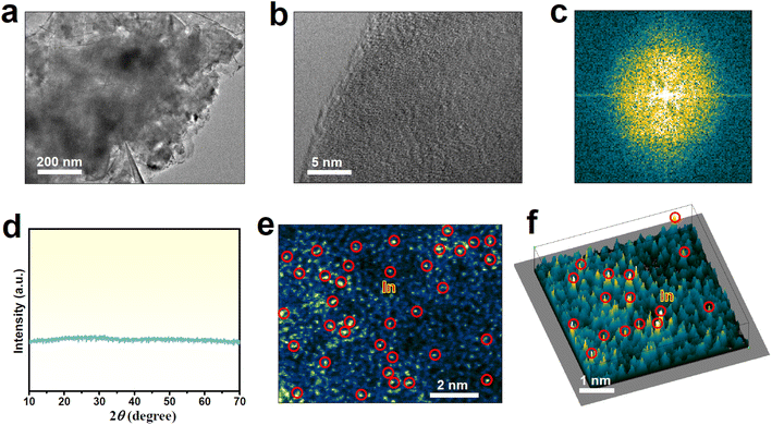
In1/a-MoO3 was prepared by a facile supercritical CO2 approach.43–45 The characteristic transmission electron microscopy (TEM, Fig. 1a) image of In1/a-MoO3 presents a nanosheet morphology, while the high-resolution TEM (HRTEM, Fig. 1b) image shows no obvious lattice fringes, similar to bare a-MoO3 (Fig. S1†). The corresponding fast Fourier transform (FFT, Fig. 1c) pattern unravels a sun-like feature, consistent with the lunar halo displayed in the selected area electron diffraction (SAED, Fig. S2†) pattern. Additionally, no noticeable diffraction peaks can be seen in the X-ray diffraction (XRD, Fig. 1d) pattern. All these HRTEM/FFT/SAED/XRD results confirm the amorphous structure of In1/a-MoO3. In the aberration-corrected high angle annular dark-field scanning transmission electron microscopy (AC-HAADF-STEM) image (Fig. 1e), there are numerous bright points (marked by red circles) that are highly dispersed on the amorphous substrate, and this can be further unveiled by the 3D intensity profile (Fig. 1f), proving that In species are atomically dispersed on a-MoO3. Elemental mapping images (Fig. S3†) display an even distribution of In single atoms over the a-MoO3 support. The In content in In1/a-MoO3 is measured to be as high as 8.2 wt%, much higher than that of reported In single atoms on carbon substrates.40,46,47
 | ||
| Fig. 1 Characterization of In1/a-MoO3: (a) TEM image, (b) HRTEM image and corresponding FFT pattern (c), (d) XRD pattern, (e) AC-HAADF-STEM image and corresponding (f) 3D intensity profile. | ||
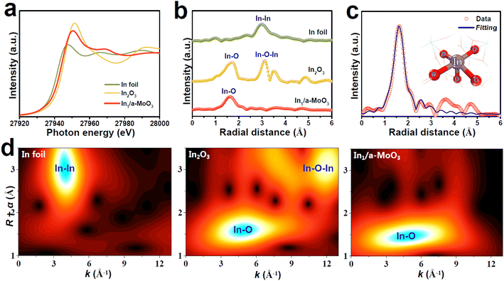
The valence states and local atomic coordination structure of In1/a-MoO3 are studied by X-ray absorption fine structure (XAFS) analyses. The In K-edge X-ray absorption near-edge structure (XANES) spectra show that the absorption edge of In1/a-MoO3 (Fig. 2a) lies between In foil and In2O3 references, indicating that In single atoms are in a positive valence state.48 In the In K-edge extended X-ray adsorption fine structure (EXAFS) spectra (Fig. 2b), In1/a-MoO3 shows a distinct peak located at 1.61 Å, which is ascribed to the In–O coordination bond. The absence of the In–In coordination bond (2.97 Å) indicates that In presents as an isolated atomic state,49–52 consistent with the AC-HAADF-STEM observation (Fig. 1e). Meanwhile, unlike the In2O3 reference, no second-shell In–O–In bond (3.09 Å) shows up in In1/a-MoO3, excluding the existence of In2O3 species on In1/a-MoO3. These EXAFS findings can be further corroborated by wavelet transform (WT) analysis (Fig. 2d), revealing that In1/a-MoO3 exhibits the solo In–O maximum intensity with no presence of In–In/In–O–In WT signals. Quantitative EXAFS fitting of In1/a-MoO3 (Fig. 2c and S4†) uncovers that single-site In is coordinated with five O atoms to form an In1–O5 motif. Moreover, ab initio molecular dynamic (AIMD, Fig. S5†) simulations reveal that the In1–O5 motif can well maintain the equilibrium temperature/energy states at temperature as high as 500 K, confirming the high thermodynamic stability of the In1–O5 motif, which is attributed to the strong In1–O5 electronic coupling to well stabilize In single atoms on the a-MoO3 substrate (Fig. S6†).
 | ||
| Fig. 2 (a) In K-edge XANES, (b) EXAFS spectra and (d) WT pattern of In1/a-MoO3 and reference samples. (c) EXAFS fitting curve of In1/a-MoO3 (inset: fitting model). | ||
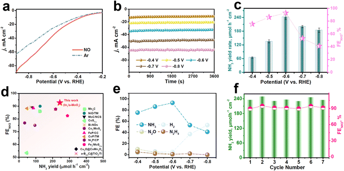
The electrocatalytic NORR properties of In1/a-MoO3 are assessed in a gas-tight H-type cell with 0.5 M Na2SO4.29 Colorimetric methods are used to detect the liquid reduction products (Fig. S7 and S8†), while gas products are detected by gas chromatography. To initially assess the NORR activity of In1/a-MoO3, we perform linear sweep voltammetry (LSV) measurements (Fig. 3a). A remarkable current density (j) enhancement can be observed in NO-solution relative to Ar-solution, verifying a good electrocatalytic NORR ability of In1/a-MoO3. We then quantify the NORR performance of In1/a-MoO3 at various potentials through combined chronoamperometry (Fig. 3b) and colorimetric methods. As shown in Fig. 3c, with increasing the potentials, In1/a-MoO3 shows a volcano-type variation in both the NH3 yield rate and FENH3, attaining their highest values of 242.6 μmol h−1 cm−2 and 92.8% at −0.6 V, respectively, which are higher than those of nearly all previously reported catalysts (Fig. 3d, Table S2†). Strikingly, In1/a-MoO3 drastically outperforms bare a-MoO3 in both the NH3 yield rate and FENH3 (Fig. S9 and S10†), suggesting that single-atomic In introduction plays a pivotal role in greatly boosting the NORR performance. The significant reduction of the NH3 yield rate and FENH3 at −0.7 V is due to the enhancement in the competing HER process (Fig. 3e). Meanwhile, Fig. 3e shows that the FENH3 of In1/a-MoO3 is much higher than the FEs of other nitrogen-containing N2 and N2H4 by-products, in accordance with the partial current density data (Fig. S11†), indicating that In1/a-MoO3 has an exceptional NORR selectivity for NO-to-NH3 conversion. The NORR stability of In1/a-MoO3 is assessed by 15 h of continuous electrolysis (Fig. S12†), which shows that the current density is rather steady and the corresponding FENH3 does not show remarkable changes, suggesting that In1/a-MoO3 has good long-term stability. Besides, during seven electrolysis cycles (Fig. 3f), the resulting NH3 yield rates and FENH3 only slightly fluctuate, proving the excellent cycling stability of In1/a-MoO3.53 After the stability test, In1/a-MoO3 well retains its nanosheet morphology, amorphous structure and atomic Ir dispersion state (Fig. S13†), demonstrating that the surface reconstruction of In1/a-MoO3 barely occurs and thus In1/a-MoO3 possesses high structural stability. Furthermore, the control colorimetric test (Fig. S14†), Ar–NO alternating cycle test (Fig. S15†), and 1H nuclear magnetic resonance test (NMR, Fig. S16†) prove that the generated NH3 comes from the NORR process.
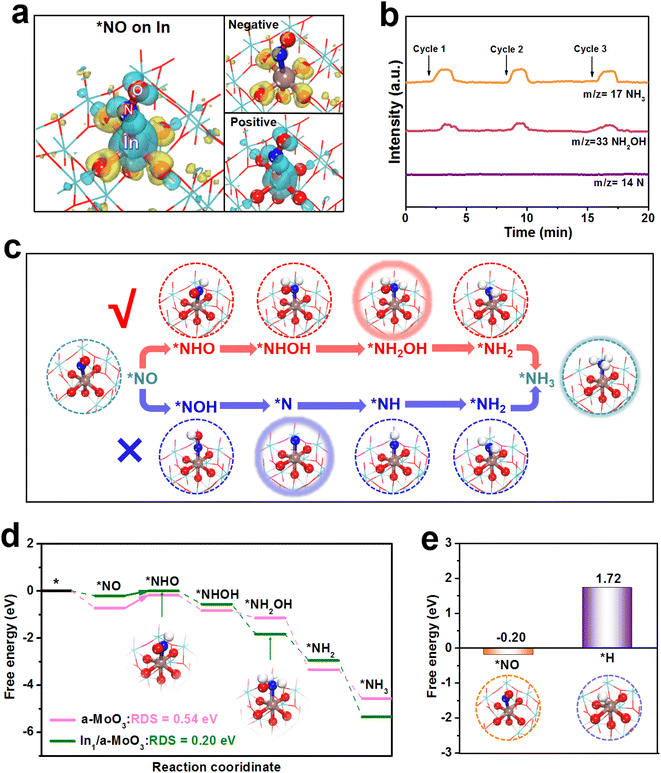
Theoretical computations are carried out to shed light on the NORR mechanism of In1/a-MoO3. Based on the EXAFS fitting result (Fig. 2c), an isolated In1–O5 motif constructed on a-MoO3 is employed to simulate In1/a-MoO3. Upon the adsorption of NO on the In site, the charge density difference map (Fig. 4a) depicts a considerable *NO/In electronic interaction. Notably, *NO shows pronounced positive charge accumulation, implying that the In site can effectively activate the NO molecule through a “σ-donation” mechanism. Prior to assessing the hydrogenation energetics of the NORR pathway, we conduct online differential electrochemical mass spectrometry (DEMS) to monitor the key intermediates and determine the optimal reaction path on In1/a-MoO3. Fig. 4b displays the absence of the N intermediate but the presence of the NH2OH intermediate, implying that In1/a-MoO3 prefers to adopt a NHO pathway (*NO → *NHO → *NHOH → *NH2OH → *NH2 → *NH3) rather than a NOH pathway (*NO → *NOH → *N → *NH → *NH2 → *NH3) to drive the NORR process (Fig. S17†),54,55 as illustrated in Fig. 4c. As shown in the free energy diagrams along the NHO pathway (Fig. 4d), the In site presents the initial *NO protonation (*NO → *NHO) as the rate-determining step (RDS) with a low energy barrier of 0.20 eV. As a sharp comparison, the Mo site of bare a-MoO3 shows the same *NO → *NHO as the RDS, but exhibits a largely increased RDS barrier of 0.54 eV due to too strong *NO binding on the Mo site. Thus, single-site In can effectively optimize the binding energy of *NO to reduce the RDS barrier, thereby significantly promoting the hydrogenation energetics of the NO-to-NH3 pathway.
As the HER is regarded as the major competitive reaction against the NORR,56–62 we further evaluate the HER activity of In1/a-MoO3. Fig. 4e shows that the binding free energy of *H (1.72 eV) on the In site is much more positive than that of *NO (−0.20 eV), proving that the In site can favorably absorb NO while restricting H binding. In the molecular dynamics (MD) simulations (Fig. S18†), *NO/In interaction is found to be much stronger than *NO/In interaction after simulations, as evidenced by the radial distribution function (RDF, Fig. S19†) curves and integrated RDF curves (Fig. S20†), verifying the priority of In1/a-MoO3 for the absorption and coverage of NO over H.63–66 Therefore, in addition to promoting the NO hydrogenation energetics, single-site In can facilitate HER suppression to enable the achievement of a high NORR selectivity.
In summary, In1/a-MoO3 is validated as an effective NORR catalyst. As unraveled by the experimental measurements and theoretical calculations, the prominent NORR properties of In1/a-MoO3 are attributed to the ability of single-site In to inhibit the HER and boost the hydrogenation energetics of the NO-to-NH3 pathway. This work would open a new avenue for the development of efficient main-group SACs for high-performance NORR electrocatalysis.
Conflicts of interest
There are no conflicts of interest to declare.Acknowledgements
This work is supported by the Central Government Guides Local Science and Technology Development Project (206Z1003G) and Fundamental Researches Top Talent Program of Lanzhou Jiaotong University (2022JC03).References
- J. Liang, Q. Liu, A. A. Alshehri and X. Sun, Nano Res. Energy, 2022, 1, e9120010 Search PubMed.
- D. Qi, F. Lv, T. Wei, M. Jin, G. Meng, S. Zhang, Q. Liu, W. Liu, D. Ma, M. S. Hamdy, J. Luo and X. Liu, Nano Res. Energy, 2022, 1, e9120022 Search PubMed.
- G. Qing, R. Ghazfar, S. T. Jackowski, F. Habibzadeh, M. M. Ashtiani, C.-P. Chen, M. R. Smith and T. W. Hamann, Chem. Rev., 2020, 120, 5437–5516 Search PubMed.
- X. Zhao, G. Hu, G. F. Chen, H. Zhang, S. Zhang and H. Wang, Adv. Mater., 2021, 33, 2007650 Search PubMed.
- K. Tanifuji and Y. Ohki, Chem. Rev., 2020, 120, 5194–5251 Search PubMed.
- K. Chu, X. Li, Q. Li, Y. Guo and H. Zhang, Small, 2021, 17, 2102363 Search PubMed.
- X. Li, Y. Luo, Q. Li, Y. Guo and K. Chu, J. Mater. Chem. A, 2021, 9, 15955–15962 Search PubMed.
- K. Chu, X. Li, Y. Tian, Q. Li and Y. Guo, Energy Environ. Mater., 2022, 5, 1303–1309 Search PubMed.
- C. Guo, J. Ran, A. Vasileff and S.-Z. Qiao, Energy Environ. Sci., 2018, 11, 45–56 Search PubMed.
- J. Deng, J. A. Iñiguez and C. Liu, Joule, 2018, 2, 846–856 Search PubMed.
- X. Cui, C. Tang and Q. Zhang, Adv. Energy Mater., 2018, 8, 1800369 Search PubMed.
- Y. Luo, P. Shen, X. Li, Y. Guo and K. Chu, Nano Res., 2022, 15, 3991–3999 Search PubMed.
- Q. Li, P. Shen, Y. Tian, X. Li and K. Chu, J. Colloid Interface Sci., 2022, 606, 204–212 Search PubMed.
- K. Chu, J. Wang, Y. Liu, Q. Li and Y. Guo, J. Mater. Chem. A, 2020, 8, 7117–7124 Search PubMed.
- M. Wang, S. Liu, T. Qian, J. Liu, J. Zhou, H. Ji, J. Xiong, J. Zhong and C. Yan, Nat. Commun., 2019, 10, 341 Search PubMed.
- J. Long, S. Chen, Y. Zhang, C. Guo, X. Fu, D. Deng and J. Xiao, Angew. Chem., Int. Ed., 2020, 59, 9711–9718 Search PubMed.
- S. Cheon, W. J. Kim, D. Y. Kim, Y. Kwon and J.-I. Han, ACS Energy Lett., 2022, 7, 958–965 Search PubMed.
- B. H. Ko, B. Hasa, H. Shin, Y. Zhao and F. Jiao, J. Am. Chem. Soc., 2022, 144, 1258–1266 Search PubMed.
- J. Wu and Y.-X. Yu, J. Colloid Interface Sci., 2022, 623, 432–444 Search PubMed.
- B. Huang, B. Chen, G. Zhu, J. Peng, P. Zhang, Y. Qian and N. Li, ChemPhysChem, 2022, 23, e202100785 Search PubMed.
- Q. Wu, H. Wang, S. Shen, B. Huang, Y. Dai and Y. Ma, J. Mater. Chem. A, 2021, 9, 5434–5441 Search PubMed.
- J. Liang, P. Liu, Q. Li, T. Li, L. Yue, Y. Luo, Q. Liu, N. Li, B. Tang, A. A. Alshehri, I. Shakir, P. O. Agboola, C. Sun and X. Sun, Angew. Chem., Int. Ed., 2022, 61, e202202087 Search PubMed.
- Y. Xiao and C. Shen, Small, 2021, 17, 2100776 Search PubMed.
- K. Chen, G. Wang, Y. Guo, D. Ma and K. Chu, Nano Res., 2023 DOI:10.1007/s12274-023-5556-7.
- K. Chen, G. Zhang, X. Li, X. Zhao and K. Chu, Nano Res., 2023 DOI:10.1007/s12274-023-5384-9.
- K. Chen, P. Shen, N. Zhang, D. Ma and K. Chu, Inorg. Chem., 2023, 62, 653–658 Search PubMed.
- T. Wei, H. Bao, X. Wang, S. Zhang, Q. Liu, J. Luo and X. Liu, ChemCatChem, 2023, 15, e202201411 Search PubMed.
- H. Zhang, Y. Li, C. Cheng, J. Zhou, P. Yin, H. Wu, Z. Liang, J. Zhang, Q. Yun and A. L. Wang, Angew. Chem., Int. Ed., 2022, e202213351 Search PubMed.
- K. Chen, J. Wang, J. Kang, X. Lu, X. Zhao and K. Chu, Appl. Catal., B, 2023, 324, 122241 Search PubMed.
- G. F. Chen, S. Y. Ren, L. L. Zhang, H. Cheng, Y. R. Luo, K. H. Zhu, L. X. Ding and H. H. Wang, Small Methods, 2019, 3, 1800337 Search PubMed.
- Y. Wang, M. M. Shi, D. Bao, F. L. Meng, Q. Zhang, Y. T. Zhou, K. H. Liu, Y. Zhang, J. Z. Wang, Z. W. Chen, D. P. Liu, Z. Jiang, M. Luo, L. Gu, Q. H. Zhang, X. Z. Cao, Y. Yao, M. H. Shao, Y. Zhang, X. B. Zhang, J. G. Chen, J. M. Yan and Q. Jiang, Angew. Chem., Int. Ed., 2019, 58, 9464–9469 Search PubMed.
- Y. Sun, Y. Wang, H. Li, W. Zhang, X.-M. Song, D.-M. Feng, X. Sun, B. Jia, H. Mao and T. Ma, J. Energy Chem., 2021, 62, 51–70 Search PubMed.
- L. Li, C. Tang, H. Jin, K. Davey and S.-Z. Qiao, Chem, 2021, 7, 3232–3255 Search PubMed.
- N. Zhang, J. Shang, X. Deng, L. Cai, R. Long, Y. Xiong and Y. Chai, ACS Nano, 2022, 16, 4795–4804 Search PubMed.
- Y. Lin, J. Liang, H. Li, L. Zhang, T. Mou, T. Li, L. Yue, Y. Ji, Q. Liu, Y. Luo, N. Li, B. Tang, Q. Wu, M. S. Hamdy, D. Ma and X. Sun, Mater. Today Phys., 2022, 22, 100611 Search PubMed.
- X. Li, G. Zhang, P. Shen, X. Zhao and K. Chu, Inorg. Chem. Front., 2023, 10, 280–287 Search PubMed.
- L. Zhang, M. Zhou, A. Wang and T. Zhang, Chem. Rev., 2019, 120, 683–733 Search PubMed.
- S. K. Kaiser, Z. Chen, D. Faust Akl, S. Mitchell and J. Pérez-Ramírez, Chem. Rev., 2020, 120, 11703–11809 Search PubMed.
- R. Lang, X. Du, Y. Huang, X. Jiang, Q. Zhang, Y. Guo, K. Liu, B. Qiao, A. Wang and T. Zhang, Chem. Rev., 2020, 120, 11986–12043 Search PubMed.
- S. Li, X. Lu, S. Zhao, M. Ceccato, X.-M. Hu, A. Roldan, M. Liu and K. Daasbjerg, ACS Catal., 2022, 12, 7386–7395 Search PubMed.
- W. Guo, X. Tan, J. Bi, L. Xu, D. Yang, C. Chen, Q. Zhu, J. Ma, A. Tayal, J. Ma, Y. Huang, X. Sun, S. Liu and B. Han, J. Am. Chem. Soc., 2021, 143, 6877–6885 Search PubMed.
- F. Luo, A. Roy, L. Silvioli, D. A. Cullen, A. Zitolo, M. T. Sougrati, I. C. Oguz, T. Mineva, D. Teschner, S. Wagner, J. Wen, F. Dionigi, U. I. Kramm, J. Rossmeisl, F. Jaouen and P. Strasser, Nat. Mater., 2020, 19, 1215–1223 Search PubMed.
- K. Chen, Y. Zhang, J. Xiang, X. Zhao, X. Li and K. Chu, ACS Energy Lett., 2023, 8, 1281–1288 Search PubMed.
- Y. Luo, Q. Li, Y. Tian, Y. Liu and K. Chu, J. Mater. Chem. A, 2022, 10, 1742–1749 Search PubMed.
- K. Chen, J. Wang, H. Zhang, D. Ma and K. Chu, Nano Lett., 2023, 23, 1735–1742 Search PubMed.
- E. Zhang, L. Tao, J. An, J. Zhang, L. Meng, X. Zheng, Y. Wang, N. Li, S. Du, J. Zhang and Y. Li, Angew. Chem., Int. Ed., 2022, 134, e202117347 Search PubMed.
- H. Shang, T. Wang, J. Pei, Z. Jiang, D. Zhou, Y. Wang, H. Li, J. Dong, Z. Zhuang, W. Chen, W. Dingsheng, J. Zhang and Y. Li, Angew. Chem., Int. Ed., 2020, 59, 22465–22469 Search PubMed.
- P. Shen, X. Li, Y. Luo, N. Zhang, X. Zhao and K. Chu, Appl. Catal., B, 2022, 316, 121651 Search PubMed.
- N. Zhang, G. Zhang, P. Shen, H. Zhang, D. Ma and K. Chu, Adv. Funct. Mater., 2023 DOI:10.1002/adfm.202211537.
- G. Wang, P. Shen, K. Chen, Y.-L. Guo, X. Zhao and K. Chu, Inorg. Chem. Front., 2023 10.1039/d2qi02757g.
- K. Chen, Z. Ma, X. Li, J. Kang, D. Ma and K. Chu, Adv. Funct. Mater., 2023 DOI:10.1002/adfm.202209890.
- X. Li, P. Shen, Y. Luo, Y. Li, Y. Guo, H. Zhang and K. Chu, Angew. Chem., Int. Ed., 2022, 134, e202205923 Search PubMed.
- G. Wang, P. Shen, Y. Luo, X. Li, X. Li and K. Chu, Dalton Trans., 2022, 51, 9206–9212 Search PubMed.
- J. Shi, C. Wang, R. Yang, F. Chen, N. Meng, Y. Yu and B. Zhang, Sci. China. Chem., 2021, 64, 1493–1497 Search PubMed.
- X. Li, K. Chen, X. Lu, D. Ma and K. Chu, Chem. Eng. J., 2023, 454, 140333 Search PubMed.
- Y. Xu, K. Shi, T. Ren, H. Yu, K. Deng, X. Wang, Z. Wang, H. Wang and L. Wang, Small, 2022, 18, 2203335 Search PubMed.
- T. Ren, Z. Yu, H. Yu, K. Deng, Z. Wang, X. Li, H. Wang, L. Wang and Y. Xu, Appl. Catal., B, 2022, 318, 121805 Search PubMed.
- T. Ren, K. Ren, M. Wang, M. Liu, Z. Wang, H. Wang, X. Li, L. Wang and Y. Xu, Chem. Eng. J., 2021, 426, 130759 Search PubMed.
- D. Wu, P. Lv, J. Wu, B. He, X. Li, K. Chu, Y. Jia and D. Ma, J. Mater. Chem. A, 2023, 11, 1817–1828 Search PubMed.
- B. He, P. Lv, D. Wu, X. Li, R. Zhu, K. Chu, D. Ma and Y. Jia, J. Mater. Chem. A, 2022, 10, 18690–18700 Search PubMed.
- D. Wu, J. Wu, P. Lv, H. Li, K. Chu and D. Ma, Small Struct., 2023 DOI:10.1002/sstr.202200358.
- W. Zhang, M. Jiang, S. Yang, Y. Hu, B. Mu, Z. Tie and Z. Jin, Nano Res. Energy, 2022, 1, e9120033 Search PubMed.
- K. Chu, Y. Luo, P. Shen, X. Li, Q. Li and Y. Guo, Adv. Energy Mater., 2022, 12, 2103022 Search PubMed.
- G. Zhang, X. Li, K. Chen, Y. Guo, D. Ma and K. Chu, Angew. Chem., Int. Ed., 2023 DOI:10.1002/anie.202300054.
- Y. Luo, K. Chen, G. Wang, G. Zhang, N. Zhang and K. Chu, Inorg. Chem. Front., 2023, 10, 1543–1551 Search PubMed.
- X. Li, P. Shen, X. Li, D. Ma and K. Chu, ACS Nano, 2023, 17, 1081–1090 Search PubMed.
Footnotes |
| † Electronic supplementary information (ESI) available. See DOI: https://doi.org/10.1039/d3ta00606a |
| ‡ These authors contributed equally to this work. |
| This journal is © The Royal Society of Chemistry 2023 |


