 Open Access Article
On design of plasma jet reactor for non-oxidative methane conversion
Giulia
De Felice
 a,
Sirui
Li
*a,
Fausto
Gallucci
a,
Nima
Pourali
b and
Evgeny
Rebrov
ab
a,
Sirui
Li
*a,
Fausto
Gallucci
a,
Nima
Pourali
b and
Evgeny
Rebrov
ab
aDepartment of Chemical Engineering and Chemistry, Eindhoven University of Technology, Eindhoven 5612 AZ, Netherlands. E-mail: s.li@tue.nl; S.Li1@tue.nl
bSchool of Engineering, University of Warwick, Coventry CV4 7AL, UK
First published on 21st February 2023
Abstract
Non-oxidative methane coupling in an atmospheric pressure plasma jet reactor with an internal diameter of 3.0 mm has been studied. The jet reactor consisted of a quartz tube surrounded by a copper ring and a stainless-steel tube, which were separated by a variable distance. The stainless-steel tube (inner diameter: 1.0 mm, outer diameter: 1.5 mm) served as high voltage electrode and gas inlet. The jet characteristics with different tip angles of the high voltage electrode were investigated using voltage–current waveforms and gas analysis at a constant methane flow rate of 100 ml min−1. The effect of the length of the ground electrode and the gap between the electrodes on conversion, C2 selectivity and energy efficiency has been studied. The methane conversion was nearly tripled with a sharp angle of the electrode (15°), while the energy consumption was reduced from 150 to 55 kJ molC2Hy−1. The carbon deposition was also reduced.
1. Introduction
Methane is the simplest and most stable organic molecule with strong carbon–hydrogen bonds (bond energy 4.55 eV, 413 kJ mol−1) and the absence of low-energy empty orbitals.1 At present, methane can be converted to ethylene either via partial oxidation to syngas and subsequent hydrogenation over a catalyst, or via a direct non-oxidative coupling route.2 Both routes are based on conventional catalysis that requires high temperature, and the second route is also prone to fast catalyst deactivation due to pore plugging by carbon deposition. The carbon deposition decreases the product yield, and regular catalyst regeneration is needed. Moreover, it can also compromise the integrity of the reactor parts, since it partially dissolves in the reactor walls, carburizing the alloys.3 The carbon deposition decreases the heat transfer rate and increases the pressure drop, causing higher operating costs.4 Thus, attempts have been made with different technologies to overcome those problems.The use of non-thermal plasma (NTP) technology is often seen as an alternative route for CH4 activation. It has generated an increasing interest for its application in natural gas and biogas processing. Indeed, plasma reactors can be powered by electricity obtained from renewable energy sources, thus effectively storing renewable energy into chemical bonds. Moreover, plasma reactors can be switched on and off easily: pre-heating/cool-down times are not required and, at the same time, reactions are extremely fast, consequently the products can be detected in few seconds after the plasma ignition.5 Therefore, plasma technologies can be easily employed for the storage of surplus electricity and peak shaving due to their high versatility. This versatility includes not only a wide range of feed gasses and energy sources exploitable, but also a high flexibility in terms of operating conditions.
Several parametric studies were conducted with different reactors and operating conditions (i.e., frequency, feed flow rate composition, addition of noble gasses, power and applied voltage).6–9 For instance, the addition of argon or helium leads to a higher methane conversion,10 however the dilution reduces the overall process efficiency and increases the operational costs due to higher number of separation steps required at the downstream, thus increasing also the process complexity.11 In general, the operating parameters influence the plasma characteristics and as a consequence, the conversion, the products distribution and the energy efficiency can be affected. By contrast, far less studies focused on improving the design of the reactors, as a key issue for the development of non-oxidative methane coupling technology.
Recently, atmospheric pressure plasma Jet (APPJ) is attracting more and more attention. APPJ reactors were studied with a variety of gases such as helium, argon, nitrogen, and air, however operations with plasma methane reforming remains scarce.12–14 Kang et al. investigated the effect of methane gas flow on the streamer propagation in a methane–air plasma jet applying a two-dimensional axisymmetric fluid model. They found out that lowering the gas velocity, a higher charge density could be observed, and thus the electric field in proximity of the streamer head was higher. The authors concluded that a lower methane flow rate is capable of supporting the propagation of the jet and the production of oxygen reactive species, whereas the presence of methane related reactive species slightly increased at higher flow rates.15 Methane reactive species density in APPJ reactors was also studied experimentally trough optical emission spectroscopy: the presence of CH, C2, and Hα radicals was detected. It was found that the relative proportion of the radicals was influenced by the operating parameters such as voltage and feed gas flow rate.16,17
In this work, non-oxidative methane coupling was studied in a lab scale dielectric barrier discharge (DBD) driven APPJ reactor to investigate and optimize the reactor design to improve methane conversion and energy efficiency. The influence of geometrical parameters on the reactor performance in methane coupling has so far received limited attention compared to operating parameters. However, geometry effects should also be studied to support the optimal design of APPJ. The present paper investigates the influence of shape of high voltage electrode, the length of the ground electrode and gap between the electrodes onto reactant conversion and energy efficiency of the reactor.
2. Experimental
The reactor consists of an inner stainless-steel tube (ID 1 mm, OD 1.5 mm) and a coaxially positioned quartz tube (ID 3 mm, OD 4 mm) with an outer copper ring (Fig. 1a). The inner tube was connected to an AC high voltage power supply, acting as a high voltage (HV) electrode while the metal ring was connected to the ground, acting as a grounded electrode (GE).The reactor design proposed is based on a DBD configuration, as the discharge is generated between the two electrodes separated by a dielectric material. This type of jet reactor has been investigated in several researches.18,19 The tip of the HV electrode was modified to have a specific angle of 15°, 30°, 60°, 180° as shown in Fig. 1b, and they are named as HV-15, HV-30, HV-60, HV-180 in this paper. Moreover, several configurations were tested with the copper ring positioned at a distance of 0, 5, 7 or 10 mm from the tip of HV electrode. The plasma jet was formed by blowing CH4 through the inner stainless steel tube when a sufficient voltage was applied to the HV electrode. A methane flow (purity 99.995%) of 100 ml min−1 was fed with an MFC (Bronkhorst® F-201CV).
The plasma reactor is powered by an AC power generator (AFS® G15S-150 K). A four-channel oscilloscope (PicoScope® 3405D) was used to record voltage waveforms. The voltage (V) across the reactor is measured with a 1![[thin space (1/6-em)]](https://www.rsc.org/images/entities/char_2009.gif) :
:![[thin space (1/6-em)]](https://www.rsc.org/images/entities/char_2009.gif) 1000 high voltage probe (Tektronix P6015A), while a 1
1000 high voltage probe (Tektronix P6015A), while a 1![[thin space (1/6-em)]](https://www.rsc.org/images/entities/char_2009.gif) :
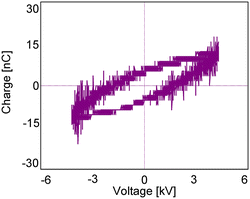
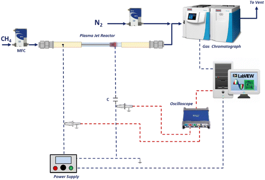
:![[thin space (1/6-em)]](https://www.rsc.org/images/entities/char_2009.gif) 10 probe (Pico TA 131) is used to measure the voltage across a 100 nF capacitor. The capacitor inserted between the ground electrode and the grounding point allows the measure of the charge (Q) transferred during the plasma discharge. Then the Lissajous figure can be generated by plotting the charges as a function of the applied voltage. The discharge power can be calculated by multiplying the area of the Lissajous figure with the operating frequency as in eqn (1).
10 probe (Pico TA 131) is used to measure the voltage across a 100 nF capacitor. The capacitor inserted between the ground electrode and the grounding point allows the measure of the charge (Q) transferred during the plasma discharge. Then the Lissajous figure can be generated by plotting the charges as a function of the applied voltage. The discharge power can be calculated by multiplying the area of the Lissajous figure with the operating frequency as in eqn (1).
| Power = f·∮VdQ = f·ALissajous | (1) |
The current waveforms were obtained using an inductive Rogowski coil (Pearson® 6600) which enables to measure alternating current. The plasma discharge was operated at a fixed frequency of 55 kHz (period 0.018 ms), while keeping the voltage at 9 kV peak-to-peak. The gas composition was analysed with a gas chromatograph (Thermo Scientific® Trace 1300) equipped with two thermal conductivity detectors and a flame ionization detector. The GC was calibrated for a range of C1–C3 hydrocarbons. A schematic of the overall setup is shown in Fig. 3.
The CH4 conversion, selectivity towards hydrogen and C2 hydrocarbons and the product yield towards C2 hydrocarbons were calculated by eqn (2)–(6). The carbon balance can be indicated by carbon lack as reported in eqn (5),20 which shows the amount of carbon that is missing in the product. This value is related to the carbon deposition on the reactor walls and the C4+ species (which have been detected by the GC but not quantified as the peaks were very low and the species were not available for calibration).
 | (2) |
 | (3) |
 | (4) |
 | (5) |
 | (6) |
 | (7) |
 | (8) |
 | (9) |
3. Results and discussion
3.1 Effect of HV electrode tip angle
Fig. 4 shows CH4 conversion and selectivity to C2 hydrocarbons, C3 hydrocarbons and hydrogen as a function of HV electrode angle. The conversion increases from 0.9 to 2.6% over the sharpest HV electrode. The selectivity to C2H6 and C3 hydrocarbons also increases to 59 and 12% respectively. Besides, the selectivity to acetylene is reduced by 25%. Considering the products obtained from the reaction, ethylene has the highest market value than ethane due to its wide employment in solvents and the plastic industry. Therefore, selectivity towards ethylene will be highly beneficial. However, the effect of the reactor geometry mainly influences the ethane selectivity in this study. Further investigation needs to be conducted to optimize the product selectivity for the purpose of methane valorisation.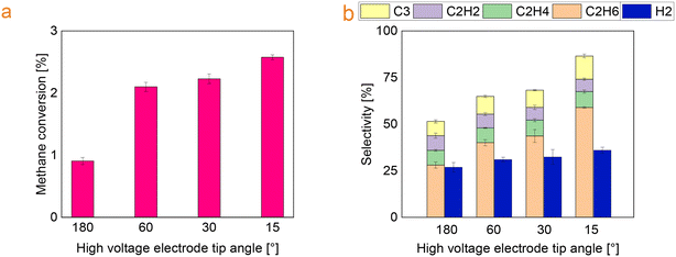 | ||
| Fig. 4 (a) Effect of the HV electrode tip angle on methane conversion and (b) selectivity towards the main products (ring electrode length: 3 mm). | ||
Moreover, in the Fig. 4b the overall selectivity does not reach 100% and the completing share is linked to the hydrocarbons with at least four carbon atoms and carbon deposition. In this study, the percentage of solids and C4+ decreases with the decrease of the tip angle. This is in line with literature data as acetylene was reported to be a precursor for soot formation as the addition of acetylenes leads to the possible formation of the first aromatic rings.11,21
The energy consumption and specific energy input are shown in Fig. 5a for the electrodes with different tip angle. A decrease of the energy consumption has been observed when reducing the high voltage electrode tip angle: the electrodes HV-15, HV-30 and HV-60 have similar energy consumption of approximately 55 kJ molC2Hy−1, nearly three times lower than the electrode HV-180. The best value for EC reported is still much higher than the thermodynamic limit calculated with the reaction enthalpy.
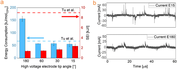 | ||
| Fig. 5 (a) Effect of HV electrode tip angle on energy consumption and specific energy input (ring electrode length: 3 mm), compared with.22 (b) Current waveform for the experiments with HV electrode tip angle 15° and 180°. | ||
Due to the limited papers available in literature on pure methane conversion with a jet reactor and the similarities with DBD reactors, comparison was made with reported studies in which DBD reactors were used. More specifically the value reported in this work is by 25% less than that reported by Tu et al.,22 yet at lower conversion.
Moreover, a rather similar performance was found in conventional thermal catalysis by Xiao et al.23 They obtained mainly ethane (C2 selectivity >90%) in non-oxidative coupling over PtBi-bimetallic catalysts with a CH4 conversion of approximately 2% at relatively mild temperatures (600–700 °C). This highlights the advantages of non-thermal plasma as similar results were achieved in this work, but the temperatures involved in our case are much lower.
Nijdam et al. suggested that when there is a local enhancement of the field at the tip, exceeding the breakdown value (Ek), a conducting streamer can develop in correspondence with this specific point, even if the background field is below breakdown.24 It has been demonstrated that the measured breakdown voltage is linked to the tip radius: a smaller radius corresponds to a lower voltage applied to the electrodes to achieve breakdown.25 Furthermore, more microdischarges are generated with sharper electrodes when the same voltage is applied and an increased number of filaments is observed.26,27 This has also been indicated by the current waveform on the HV-15 electrode reported in Fig. 5b (red curve), showing the appearance of several spikes, which are assumed to be associated with microdischarges formation. On the other hand, the HV-180 electrode shows fewer spikes (Fig. 5b, black curve). These spikes correspond to filamentary discharges with dimensions of hundreds of microns and lifetime in the range of hundred nanoseconds or less.28
It was suggested that the energy transfer between the accelerated electrons and the molecules happens within the microdischarges.29 Therefore, the filaments are capable of increasing the chance of reaction and as a consequence, they influence the overall performance of the process, acting as reaction channels.30 As the number of microdischarges increase, the probability for a single gas molecule be reacted is higher. Therefore, higher number of microdischarges lead to higher conversion, as reported in literature.31–33 The sharpest electrode (HV-15) was used for further studies.
3.2 Effect of the distance between electrodes
In this series of experiments, the ground electrode was positioned at a vertical distance of 0, 5, 7, and 10 mm from the tip of the high voltage electrode. The increase of the distance between the high voltage electrode and the ground electrode resulted in an increase in methane conversion from approximately from 1.4% to 2.6%. In addition, it was found that the selectivity towards ethane increases along with the distance, whereas the selectivity towards saturated hydrocarbons slightly decreases (Fig. 6).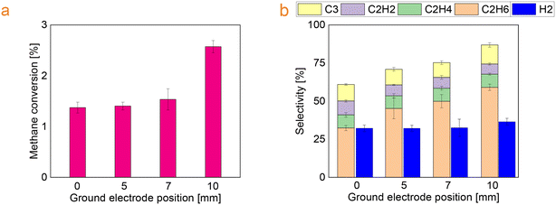 | ||
| Fig. 6 (a) Methane conversion and (b) selectivity towards the main products as a function of the position of the ground electrode. | ||
The increase of the distance between the electrodes lead to the increase of the discharge volume between electrodes (from 21 mm3 to 92 mm3) which consequently leads to the increase of the residence time of the reactant, as reported in Table 1. As already mentioned, only the volume between the electrodes was used to calculate the residence time and considered active in the gas conversion. Increasing the residence time implies that the time interval during which excited species, molecules, electrons and radicals can collide and react is longer. On the other hand, increasing the gap between the two electrodes, the overall power density (eqn (8)) provided into the discharge zone is lower.
| Distance, mm | Plasma volume, mm3 | Residence time, ms | Power density, W mm−3 |
|---|---|---|---|
| 0 | 21 | 13 | 0.10 |
| 5 | 57 | 34 | 0.05 |
| 7 | 71 | 42 | 0.04 |
| 10 | 92 | 55 | 0.04 |
The influence of the power density and the residence time on conversion compensate each other. Looking at the results related to the tests at 0 and at 5 mm, it can be observed that the residence time increases approximately 2.6 times, whereas the power density is halved. As a result, the conversion mildly increases. Nevertheless, looking at the tests at 7 and at 10 mm which have similar power densities, a large increase of the methane conversion was achieved at 10 mm. This can be explained with reference to a 25% increase of the residence time. Under similar power density, higher residence time resulted in more exposure of the reactant to plasma, hence more chances for the reaction to occur and higher conversion of methane was achieved in the case of 10 mm distance. This is in line with the previous study reported by Gao et al. who also demonstrated the influence of residence time34
Differences in product distribution were also observed in this series of tests. Despite the complexity of reaction mechanisms, many studies have reported that the reaction is initiated by methane dissociation via electron impact reactions to produce methyl radicals.11,35 CH3, CH2, CH, and C can be produced in sequence. However, the relative proportion of the CHi (i = 0–3) radicals depends on the strength of the electric field. When the mean electron energy is lower, the high concentration of methyl radical may favour the radical recombination to ethane due to the abundance of the reactant.36 Moreover, ethane can also be formed from the reaction of methane molecules with CH2 radicals. Then, the produced ethane can go through successive dehydrogenations to produce more hydrocarbons via a series of reactions.37 On the other hand, the electron impact will lead to the formation of CH and C radicals, promoting the formation of ethylene and acetylene when the mean electron energy is high.38
As mentioned, CHi radicals can undergo recombination reactions, giving ethane, ethylene and acetylene as products. In particular, acetylene and ethylene are potentially reactive, as they may participate in the formation of carbon deposition.39 The soot can be formed by radicals obtained via hydrogen atom removal that can polymerize, triggering the formation of larger hydrocarbons and carbon deposition.40
Moreover, the dehydrogenation reactions are very fast, this can explain the significant increase of the carbon deposition compared with the relatively modest increase of the unsaturated hydrocarbons.
The electrodes position affects the EC: increasing the distance the energy consumption decreases from 85 to 55 kJ molC2Hy−1 as shown in Fig. 7. The negative effects, such as the lower power density, related to the increased electrode gap can be counterbalanced by the extending of the residence time within the experiment range in this study.
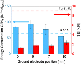 | ||
| Fig. 7 Energy consumption and specific energy input as a function of the distance between the electrodes.22 | ||
3.3 Effect of ground electrode length
Keeping the high voltage electrode tip angle as 15° and electrodes distance as 10 mm, the length of the ground electrode was extended from 2 to 5 mm. It was found that the conversion decreased from 2.7 to 1.5% (Fig. 8a) with a simultaneous increase in selectivity towards C2H2, C2H4 and C4+ hydrocarbons (Fig. 8b).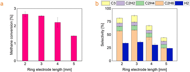 | ||
| Fig. 8 (a) Methane conversion and (b) selectivity towards the main products as a function of ring electrode length. | ||
In this case, increasing the ring electrode length, the volume of the plasma zone between electrodes expands (from 85 mm3 to 105 mm3) and the surface covered by the electrode increases (from 25 mm2 to 65 mm2). Longer residence time increases the probability for the methane molecules to interact with the reactive species in the plasma environment.41 Besides, a larger surface area implies also higher heat loss, as part of electrical energy available in the discharge zone might also be dissipated to heat the dielectric material.42
Since methane decomposition is an endothermic reaction, the formation of carbon deposition is favoured at high temperatures. Moreover, the carbon generation in cold plasma can be linked to the direct collision of CHx molecule with electrons,43 but also to the reactor walls temperature. The study by Yap et al. proved that increasing the temperature of the reactor walls enhances the carbon formation.44 This is in line with our case, less carbon deposition was observed on the reactor with shorter ground electrodes as shown in Fig. 9.
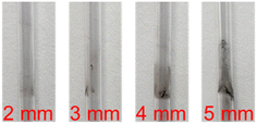 | ||
| Fig. 9 Optical images of the quartz tubing after the reaction with different ground electrode length. | ||
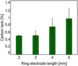
Moreover the carbon lack is reported in Fig. 10 as a function of the ring electrode length. With shorter ground electrodes, it has been found that the carbon lack is lower. This is in agreement with the carbon deposition observed on the reactor wall as shown in Fig. 9.
The energy consumption and specific energy input are shown in Fig. 11. There is no clear trend with the length of the electrode, but a much higher energy consumption was observed in the case with the longest electrode. This can be linked to increased heat losses and the formation of discharges outside the reactor such as corona in the gap between the ground electrode and the quartz tube.45 Due to the configuration of the grounded electrode (copper wire twisted and wrapped around the dielectric tube wall) and the higher thermal expansion of metal compared with quartz, a small quantity of air can be trapped in the gap between the ground electrode and the quartz tube, where abnormal corona can take place.46 As the energy consumed by this phenomenon is wasted outside the reactor and it is not employed to enhance the conversion, it can be linked directly to higher energy consumption.47 In the study by Kim et al., this wasted energy has been estimated and it could reach up to 40%.48 To verify this point in our study, discharge outside the reactor was prevented by adding a dielectric clay (Blue Tack®) between the grounded electrode and the dielectric tube to fill the air voids, and the energy consumption was reduced by 27% in this case.
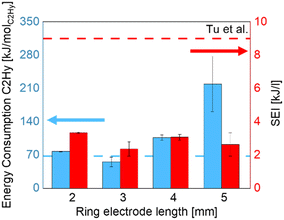 | ||
| Fig. 11 Energy consumption and specific energy input as a function of ring electrode length.22 | ||
4. Conclusions
Methane conversion was studied in an atmospheric pressure plasma jet reactor. The energy consumption and SEI found in this work are summarized in Table 2 with optimal value highlighted in bold.| Reactor design parameters | Energy consumption [kJ molC2Hy−1] | SEI [kJ l−1] |
|---|---|---|
| High voltage electrode angle 15° | 55 | 2.36 |
| High voltage electrode angle 30° | 58 | 1.69 |
| High voltage electrode angle 60° | 57 | 1.46 |
| High voltage electrode angle 180° | 155 | 1.38 |
| Distance between electrodes 0 mm | 85 | 1.30 |
| Distance between electrodes 5 mm | 93 | 1.78 |
| Distance between electrodes 7 mm | 77 | 1.73 |
| Distance between electrodes 10 mm | 55 | 2.36 |
| Ground electrode length 2 mm | 77 | 3.33 |
| Ground electrode length 3 mm | 55 | 2.36 |
| Ground electrode length 4 mm | 106 | 3.06 |
| Ground electrode length 5 mm | 219 | 2.63 |
The high voltage electrode tip angle of 15° provided the highest methane conversion and the highest selectivity toward ethane of 59%, while the energy consumption was reduced by 25%, reaching a value of 55 kJ molC2Hy−1. The optimal position of the ground electrode at 10 mm relative to the tip of HV electrode reduced the energy consumption and doubled the methane conversion. Finally reducing the length of the ground electrode, the energy consumption and the carbon deposition reduced as well. Therefore, appropriate selection of electrode configurations and position leads to a plasma jet reactor with higher efficiency.
Conflicts of interest
There are no conflicts to declare.Acknowledgements
The authors acknowledge support from the ERC Synergy Grant “Surface-Confined fast modulated plasma for process, energy intensification” (SCOPE) from the European Commission with the Grant No. 810182, and Eindhoven Institute for Renewable Energy Systems (EIRES).References
- P. Tang, Q. Zhu, Z. Wu and D. Ma, Methane activation: the past and future, Energy Environ. Sci., 2014, 7(8), 2580–2591, 10.1039/c4ee00604f.
- R. S. Abiev, D. A. Sladkovskiy, K. V. Semikin, D. Y. Murzin and E. V. Rebrov, Non-thermal plasma for process and energy intensification in dry reforming of methane, Catalysts, 2020, 10, 1–41, DOI:10.3390/catal10111358.
- M. J. Bennett, Carbon deposition: A major technological problem, Mater. Corros. - Werkst. Korros., 1998, 49, 345–351, DOI:10.1002/(SICI)1521-4176(199805)49:5<345::AID-MACO345>3.0.CO;2-1.
- X. Cheng, S. Feng and Q. Bi, Surface coke deposition influences on flow and heat transfer of hydrocarbon fuel in circular tubes with twisted-tape inserts, Int. Commun. Heat Mass Transfer, 2021, 122, 105125, DOI:10.1016/J.ICHEATMASSTRANSFER.2021.105125.
- R. Snoeckx, Y. X. Zeng, X. Tu and A. Bogaerts, Plasma-based dry reforming: Improving the conversion and energy efficiency in a dielectric barrier discharge, RSC Adv., 2015, 5, 29799–29808, 10.1039/c5ra01100k.
- S. Y. Liu, D. H. Mei, Z. Shen and X. Tu, Nonoxidative conversion of methane in a dielectric barrier discharge reactor: Prediction of reaction performance based on neural network model, J. Phys. Chem. C, 2014, 118, 10686–10693, DOI:10.1021/jp502557s.
- L.-T. Hsieh, W.-J. Lee, C.-Y. Chen, M.-B. Chang and H.-C. Chang, Converting Methane by Using an RF Plasma Reactor, Plasma Chem. Plasma Process., 1998, 18(2), 215–239 CrossRef CAS.
- J.-Q. Zhang, Y.-J. Yang, J.-S. Zhang, Q. Liu and K.-R. Tan, Non-Oxidative Coupling of Methane to C 2 Hydrocarbons under Above-Atmospheric Pressure Using Pulsed Microwave Plasma, Energy Fuels, 2002, 16(3), 687–693, DOI:10.1021/ef010217u.
- Y. Yang, Direct Non-oxidative Methane Conversion by Non-Thermal Plasma: Experimental Study, Plasma Chem. Plasma Process., 2003, 23, 283–296, DOI:10.1023/A:1022968002315.
- A. You, M. A. Y. Be and I. In, Methane activation using noble gases in a dielectric barrier discharge reactor, Phys. Plasmas, 2013, 20(8), 083509, DOI:10.1063/1.4818795.
- M. Scapinello, E. Delikonstantis and G. D. Stefanidis, The panorama of plasma-assisted non-oxidative methane reforming, Chem. Eng. Process., 2017, 117, 120–140, DOI:10.1016/j.cep.2017.03.024.
- M. Qian, S. Liu, C. Yang, X. Pei, X. Lu, J. Zhang and D. Wang, An experimental study on discharge characteristics in a pulsed-dc atmospheric pressure CH3OH/Ar plasma jet, Plasma Sources Sci. Technol., 2016, 25(5) DOI:10.1088/0963-0252/25/5/055012.
- M. Qian, G. Li, J. Kang, S. Liu, C. Ren, J. Zhang and D. Wang, Fluid modeling of radical species generation mechanism in dense methane-air mixture streamer discharge, Phys. Plasmas, 2018, 25, 13519, DOI:10.1063/1.5016855.
- H. Long, S. Shang, X. Tao, Y. Yin and X. Dai, CO2 reforming of CH4 by combination of cold plasma jet and Ni/γ-Al2O3 catalyst, Int. J. Hydrogen Energy, 2008, 33, 5510–5515, DOI:10.1016/j.ijhydene.2008.05.026.
- J. Kang, M. Qian, G. Li, S. Liu, C. Ren, J. Zhang and D. Wang, The effect of methane gas flow rate on the streamer propagation in an atmospheric-pressure methane-air plasma jet, Phys. Plasmas, 2018, 25, 93508, DOI:10.1063/1.5046946.
- A. Yanguas-Gil, K. Focke, J. Benedikt and A. Von Keudell, Optical and electrical characterization of an atmospheric pressure microplasma jet for ArC H4 and Ar C2 H2 mixtures, J. Appl. Phys., 2007, 101, 103307, DOI:10.1063/1.2714646.
- J. Zhang, X. Bian, Q. Chen, Y. Zhang and F. Liu, Optical spectroscopy diagnosis of methane plasma generated with atmospheric pressure jet, J. Vac. Sci. Technol., A, 2009, 29(3), 268–272 CAS.
- D. Kong, F. He, B. Yang, Z. Duan, R. Han, J. Miao, X. Yan and J. Ouyang, Multiple current pulse behavior and its dynamics of atmospheric pressure plasma jet in a needle-to-ring configuration, J. Phys. D: Appl. Phys., 2021, 54(40) DOI:10.1088/1361-6463/ac08cb.
- S. Javanmard and S. Pouryoussefi, Comparison of characteristics of atmospheric pressure plasma jets using argon and helium working gases, Current Applied Physics, 2023, 46, 61–69, DOI:10.1016/j.cap.2022.12.002.
- M. Scapinello, E. Delikonstantis and G. D. Stefanidis, Direct methane-to-ethylene conversion in a nanosecond pulsed discharge, Fuel, 2018, 222, 705–710, DOI:10.1016/J.FUEL.2018.03.017.
- H. Richter and J. B. Howard, Formation of polycyclic aromatic hydrocarbons and their growth to soot—a review of chemical reaction pathways, Prog. Energy Combust. Sci., 2000, 26, 565–608, DOI:10.1016/S0360-1285(00)00009-5.
- C. Xu and X. Tu, Plasma-assisted methane conversion in an atmospheric pressure dielectric barrier discharge reactor, J. Energy Chem., 2013, 22, 420–425, DOI:10.1016/S2095-4956(13)60055-8.
- Y. Xiao and A. Varma, Highly Selective Nonoxidative Coupling of Methane over Pt-Bi Bimetallic Catalysts, ACS Catal., 2018, 8(4), 2735–2740, DOI:10.1021/acscatal.8b00156.
- S. Nijdam, J. Teunissen and U. Ebert, The physics of streamer discharge phenomena, Plasma Sources Sci. Technol., 2020, 29(10) DOI:10.1088/1361-6595/abaa05.
- P. Simka, E. M. Borrelli and A Blaszczyk, Air Breakdown at Sharp Edges, 2018 IEEE 2nd Int. Conf. Dielectr. ICD, 2018, pp. 1–4, DOI:10.1109/ICD.2018.8468399.
- N. Khamsen, A. Akkarachanchainon, K. Fookiat, J. Srisala, S. Chomchuen, W. Kanokbannakorn and S. Srisonphan, Atmospheric Cold Plasma via Fringe Field Enhanced Corona Discharge on Single Dielectric Barrier for Large-volume Applications, Procedia Comput. Sci., 2016, 86, 321–324, DOI:10.1016/j.procs.2016.05.087.
- Y. Wang, H. Yan, H. Guo, Y. Xu, Z. Fan and C. Ren, Effect of airflow on the space-time distribution of filaments in dielectric barrier discharge at atmospheric pressure, Phys. Plasmas, 2020, 27(3) DOI:10.1063/1.5139977.
- B. Eliasson and U. Kogelschatz, Modeling and Applications of Silent Discharge Plasmas, IEEE Trans. Plasma Sci., 1991, 19, 309–323, DOI:10.1109/27.106829.
- D. Li-Fang, L. Xue-Chen, Y. Zeng-Qian, Q. Sheng-Fa, O. Ji-Ting and W. Long, Self-Organized Filaments in Dielectric Barrier Discharge in Air at Atmospheric Pressure, Chin. Phys. Lett., 2001, 18, 1380–1382, DOI:10.1088/0256-307x/18/10/326.
- D. Mei, Y. L. He, S. Liu, J. Yan and X. Tu, Optimization of CO2 Conversion in a Cylindrical Dielectric Barrier Discharge Reactor Using Design of Experiments, Plasma Processes Polym., 2016, 13, 544–556, DOI:10.1002/ppap.201500159.
- N. Lu, C. Zhang, K. Shang, N. Jiang, J. Li and Y. Wu, Dielectric barrier discharge plasma assisted CO2 conversion: Understanding the effects of reactor design and operating parameters, J. Phys. D: Appl. Phys., 2019, 52, 224003, DOI:10.1088/1361-6463/ab2171.
- A. Ozkan, T. Dufour, A. Bogaerts and F. Reniers, How do the barrier thickness and dielectric material influence the filamentary mode and CO2 conversion in a flowing DBD?, Plasma Sources Sci. Technol., 2016, 25(4) DOI:10.1088/0963-0252/25/4/045016.
- J. A. Andersen, J. M. Christensen, M. Østberg, A. Bogaerts and A. D. Jensen, Plasma-catalytic ammonia decomposition using a packed-bed dielectric barrier discharge reactor, Int. J. Hydrogen Energy, 2022, 47(75), 32081–32091, DOI:10.1016/J.IJHYDENE.2022.07.102.
- Y. Gao, S. Zhang, H. Sun, R. Wang, X. Tu and T. Shao, Highly efficient conversion of methane using microsecond and nanosecond pulsed spark discharges, Appl. Energy, 2018, 226, 534–545, DOI:10.1016/j.apenergy.2018.06.006.
- S. Ravasio and C. Cavallotti, Analysis of reactivity and energy efficiency of methane conversion through non thermal plasmas, Chem. Eng. Sci., 2012, 84, 580–590, DOI:10.1016/J.CES.2012.09.012.
- S. Zhang, Y. Gao, H. Sun, H. Bai, R. Wang and T. Shao, Time-resolved characteristics and chemical kinetics of non-oxidative methane conversion in repetitively pulsed dielectric barrier discharge plasmas, J. Phys. D: Appl. Phys., 2018, 51(27) DOI:10.1088/1361-6463/aac5ad.
- X. Hu, Y. Liu, L. Dou, C. Zhang, S. Zhang, Y. Gao, X. Tu and T. Shao, Plasma enhanced anti-coking performance of Pd/CeO2catalysts for the conversion of methane, Sustainable Energy Fuels, 2022, 6, 98–109, 10.1039/d1se01441b.
- D. Hoon Lee, K.-T. Kim, Y.-H. Song, W. Suk Kang and S. Jo, Mapping Plasma Chemistry in Hydrocarbon Fuel Processing Processes, Plasma Chem. Plasma Process., 2013, 33(1), 249–269, DOI:10.1007/s11090-012-9407-7.
- M. Taheraslani and H. Gardeniers, Plasma Catalytic Conversion of CH4 to Alkanes, Olefins and H2 in a Packed Bed DBD, Reactor, 2020, 8(7) DOI:10.3390/pr8070774.
- K. De Bleecker, A. Bogaerts and W. Goedheer, Detailed modeling of hydrocarbon nanoparticle nucleation in acetylene discharges, Phys. Rev. E: Stat., Nonlinear, Soft Matter Phys., 2006, 73, 1–16, DOI:10.1103/PhysRevE.73.026405.
- A. Zhou, D. Chen, C. Ma, F. Yu and B. Dai, DBD Plasma-ZrO 2 Catalytic Decomposition of CO 2 at Low Temperatures, Catalysts, 2018, 8(7) DOI:10.3390/catal8070256.
- T. Hammer, T. Kappes and M. Baldauf, Plasma catalytic hybrid processes: Gas discharge initiation and plasma activation of catalytic processes, Catal. Today, 2004, 89, 5–14, DOI:10.1016/j.cattod.2003.11.001.
- D. Hoon Lee, Y.-H. Song, K.-T. Kim and J.-O Lee, Comparative Study of Methane Activation Process by Different Plasma Sources, Plasma Chem. Plasma Process., 2013, 33(4), 647–661, DOI:10.1007/s11090-013-9456-6.
- D. Yap, J. M. Tatibouët and C. Batiot-Dupeyrat, Carbon dioxide dissociation to carbon monoxide by non-thermal plasma, J. CO2 Util., 2015, 12, 54–61, DOI:10.1016/j.jcou.2015.07.002.
- M. Rahimpour, H. Taghvaei, S. Zafarnak, M. R. Rahimpour and S. Raeissi, Post-discharge DBD plasma treatment for degradation of organic dye in water: A comparison with different plasma operation methods, J. Environ. Chem. Eng., 2019, 7, 103220, DOI:10.1016/J.JECE.2019.103220.
- L. Sivachandiran, J. Karuppiah and C. Subrahmanyam, DBD plasma reactor for oxidative decomposition of chlorobenzene, Int. J. Chem. React. Eng., 2012, 10(1) DOI:10.1515/1542-6580.2785.
- O. Khalifeh, A. Mosallanejad, H. Taghvaei and M. Reza, Decomposition of methane to hydrogen using nanosecond pulsed plasma reactor with different active volumes , voltages and frequencies, Appl. Energy, 2016, 169, 585–596, DOI:10.1016/j.apenergy.2016.02.017.
- H.-H. Kim, S.-M. Oh, A. Ogata and S. Futamura, Decomposition of benzene using Ag/TiO 2 packed plasma-driven catalyst reactor: influence of electrode configuration and Ag-loading amount, Catal. Lett., 2004, 96, 189–194, DOI:10.1023/B:CATL.0000030119.69922.07.
| This journal is © The Royal Society of Chemistry 2023 |


