Sodium doping for enhanced performance by highly efficient CsPbBr3 quantum dot-based electroluminescent light-emitting diodes†
Yi
Huang
a,
Pengfei
Tang
a,
Wenxia
Zhang
 *a,
Wensheng
Yan
a,
Bin
Liu
b,
Xiaosheng
Tang
*ac,
Zhen
Wang
a,
Yue
Peng
a and
Weiwei
Chen
 *a
*a
aCollege of Optoelectronic Engineering, Chongqing University of Post and Telecommunications, Chongqing 400065, People's Republic of China. E-mail: zhangwx@cqupt.edu.cn; xstang@cqupt.edu.cn; chenww@cqupt.edu.cn
bSchool of Electronic Science and Engineering, Nanjing University, Nanjing 210093, People's Republic of China
cSchool of Materials Science and Engineering, Zhengzhou University, Zhengzhou 450001, People's Republic of China
First published on 1st February 2022
Abstract
Metal halide perovskite quantum dots (QDs) are emerging as promising materials for illumination and display applications owing to their unique optical and electronic properties. However, research into the doping of perovskite QDs with alkali metal cations for use in light-emitting diode (LED) devices is limited. Herein, a facile and convenient room-temperature method for synthesizing Na+-ion-doped CsPbBr3 QDs is presented. Through the optimization of the Na+ doping concentration, the as-prepared Na+-doped CsPbBr3 QDs display a higher photoluminescence quantum yield of 94.74%, faster radiative recombination rate of 30.4 μs−1, and longer lifetime of 31.2 ns than their undoped counterparts, allowing the practical realization of high-efficiency electroluminescent QD LED (QLED) devices. As a result, a maximum luminance of 20![[thin space (1/6-em)]](https://www.rsc.org/images/entities/char_2009.gif) 190 cd m−2, a peak current efficiency of 34.5 cd A−1, and an external quantum efficiency of 8.97% for as-fabricated QLEDs are obtained; all these characteristics are higher than those of the control device with undoped CsPbBr3 QDs. Experimental studies combined with auxiliary theoretical calculations indicate that the enhanced performance can be chiefly attributed to the decreased trap defect density of the perovskite upon sodium incorporation. This research indicates the immense potential of the Na+-doped CsPbBr3 QDs to act as an emission layer for use in the next-generation illumination and display fields.
190 cd m−2, a peak current efficiency of 34.5 cd A−1, and an external quantum efficiency of 8.97% for as-fabricated QLEDs are obtained; all these characteristics are higher than those of the control device with undoped CsPbBr3 QDs. Experimental studies combined with auxiliary theoretical calculations indicate that the enhanced performance can be chiefly attributed to the decreased trap defect density of the perovskite upon sodium incorporation. This research indicates the immense potential of the Na+-doped CsPbBr3 QDs to act as an emission layer for use in the next-generation illumination and display fields.
1. Introduction
The component structure of all inorganic metal halide perovskite quantum dots (QDs) is CsPbX3 (X = Cl, Br, I). Since their first successful preparation by the Kovalenko group in 2015,1 the exploration of CsPbX3 (X = Cl, Br, I) QDs has aroused great interest in researchers because of their excellent properties, such as color tunability, narrow photoluminescence (PL) spectrum, high photoluminescence quantum yield (PLQY) and long carrier lifetime, as well as their low trap state density.2–6 Recently, the development and application of solution processing of halogenated perovskites has changed the traditional semiconductor production route worldwide. With their intriguing advantages, perovskite QDs have been widely used for many applications in light-emitting diodes (QLEDs),7 solar cells,8 photodetectors,9 resistive switching memory and other electronic devices.10 In particular, through the modification of the CsPbX3 QDs and optimization of the device structure, the external quantum efficiency (EQE) of the CsPbX3-QD-based electroluminescent (EL) LED devices has been significantly improved from the first reported value of 0.12% to 21%.11,12Even though perovskite QDs have made great progress in QLED devices,13–16 the surface defects of perovskite QDs are still the main problem hindering their further practical application. At present, CsPbX3 QDs are generally obtained via the hot-injection method,17 ligand-assisted reprecipitation method,18 ultrasonic method,19 microwave-assisted method,20 and template method.21 For the purposes of large-scale fabrication and low cost, the ligand-assisted reprecipitation method is the recommended synthetic method. Generally, the surface ligands, such as oleic acid and oleylamine, are important for stabilizing perovskite QDs and passivating the non-radiative recombination defects. However, because of the insulating properties of these ligands,22 the charge transfer ability of the QDs will be weakened,23 which has adverse effects on the performance of QLED devices.
To date, surface passivation technology and the metal ion doping method have been demonstrated to be effective approaches to decrease the defect states in perovskite QDs. For instance, Young-Hoon Kim and coworkers reported the effects of amine ligands with different lengths, i.e., n-butylamine (C4N9NH2), n-hexylamine (C6N13NH2) and n-octylamine (C8N17NH2), on CH(NH2)2PbBr3 QDs; the results showed that the shorter ligands could greatly improve the charge injection and transportation properties of the QDs.20 Bakr and coworkers adopted the shorter ligand didodecyldimethylammonium bromide (DDAB) to replace the common ligands oleic acid and oleylamine, resulting in an obvious improvement in LED efficiency.24 In addition, covering the QD surface with a wide bandgap semiconductor (CdS, ZnS) also plays a key role in passivating the defects and improves the electrical properties of perovskite QDs. Unfortunately, although this method has been successfully applied to traditional II–VI or III–V semiconductor QDs,25,26 it is difficult to cover CsPbX3 QDs with a wide bandgap semiconductor, because this type of QDs are ionic crystals, and the ion (metal or halogen) exchange phenomenon occurs easily. Therefore, doping metal ions into CsPbX3 QDs has become a common method to enhance the properties of QD materials. In previous reports, doping with metal ions, such as Ce3+, Zn2+, Cd2+, Mn2+, Sn2+, and K+,27,28 has been used to improve the quality of perovskite QDs and performance of QLED devices. For example, Kim and colleagues demonstrated that doping Ni2+ into CsPbBr3 QDs can effectively enhance their stability and PLQY.29 Compared with those dealing with B-site ion doping, there are relatively few reports on A-site cation doping. For example, Hoang and co-workers introduced K+ ions into the CsPbBr3 lattice, partially replacing the position of the Cs+ ions.30 By adjusting the K+-ion-doping concentration, the PLQY of the CsPbBr3 QDs is increased to 83.2%, revealing that introducing A-site cation doping is an effective way to adjust the optical properties of CsPbX3 QDs. All these explorations demonstrated that ion-doped CsPbBr3 QDs display potential for fabricating QLED devices. However, their performance is still hovering at a relatively low level, although the doped CsPbBr3 QDs display high PL QYs and stability. For instance, the EQE of the Mn2+-doped CsPbBr3-based QLED device from the Zeng group is only 1.49%.31 The Hoang group reported an EQE of 5.6% through the use of K+-doped CsPbBr3 QDs as an emission layer.30 Recently, Kim achieved an EQE of 2.4% by using Ni+-doped CsPbBr3 perovskite QDs in a device.29 These unsatisfying results encourage us to explore a feasible doping strategy to boost the efficiency of perovskite QLED devices.
In this work, we propose a facile but valid strategy for the fabrication of Na+-ion-doped CsPbBr3 QDs. The effects of the Na+ doping on the morphology, structure, and optical properties of the QDs and the final devices are studied in detail. Compared to the pure CsPbBr3 QDs, the optimized Na+-doped CsPbBr3 QDs display a higher PLQY of 94.74% and a longer lifetime of 31.2 ns, demonstrating that Na+ doping is beneficial to passivate defects in the CsPbBr3 QDs. The resulting QLED based on the Na+-doped-CsPbBr3 QDs exhibited a current efficiency of 34.5 cd A−1 and an EQE of 8.97%, which were about 2.2-fold and 1.8-fold higher, respectively, than those of the devices with undoped CsPbBr3 QD-based QLEDs. Our work suggests that Na+-doped CsPbBr3 QDs can serve as a luminescent material in QLED applications and other optoelectronic devices.
2. Experimental section
2.1 Materials
Cesium carbonate (Cs2CO3, 99.9%), sodium oleate (NaOA, 98%), formamidine acetate (FA(Ac), 99%), lead bromide (PbBr2, 99.99%), tetra-n-octyl ammonium bromide (TOAB, 98%), octanoic acid (OTAc, 99%) were bought from Macklin Inc. Didodecyl dimethylammonium (DDAB, 98%) was purchased from Yuanye Corporation. Poly(3,4-ethylenedioxythiophene):poly(styrene sulfonate) (PEDOT:PSS), poly[bis(4-phenyl)(2,4,6-trimethylphenyl)amine] (PTAA), 1,3,5-tris(1-phenyl-2-benzimidazolyl)benzene (TPBi), LiF, and Al were purchased from Xi’an Polymer Light Technology Corporation. Ethyl acetate and toluene were of analytical grade and obtained from Aladdin.2.2 Synthesis of Na+-doped CsPbBr3 QDs
The Na+-doped CsPbBr3 perovskite QDs were synthesized at room temperature. First, 0.1 mmol of Cs2CO3 and NaOA were loaded into a centrifuge tube with 1 mL of OTAc. The Na:Cs proportions were controlled at 0, 1/3, 1, and 4. Subsequently, 0.2 mmol of FA(Ac) was loaded into a centrifuge tube with 1 mL of OTAc. The PbBr2 precursor solution was obtained by dissolving 1 mmol of PbBr2 and 2 mmol of TOAB in 10 mL of toluene, and the DDAB solution was obtained by dissolving 10 mg of DDAB in 1 mL toluene. Next, 0.85 mL of the cesium/sodium mixed precursor solution and 0.15 mL of the FA(Ac) solution were injected into 9 mL of the PbBr2 toluene solution. The solution was stirred and reacted for 5 min. After that, 3 mL of the DDAB solution was poured into the PbBr2 precursor solution to obtain the crude solution of CsPbBr3. After 2 min, two equivalents of ethyl acetate were added to the CsPbBr3 crude solution, and it was centrifuged at 9000 rpm for 5 min. The precipitate was collected and redispersed in toluene. The process was repeated once more, and the precipitate was collected, redispersed in hexane and centrifuged at 4000 rpm for 5 min. Finally, the supernatant was filtered using a 0.22 μm filter.2.3 Fabrication of QLED devices
Pre-patterned ITO (South China Science Technology) glass substrates were cleaned using detergent, deionized water, acetone, and ethanol for 15 min each. After drying, the ITO substrates were treated with ultraviolet/oxygen for at least 30 min. A PEDOT:PSS solution (filtered through a 0.22 μm filter) was spin-coated onto the ITO glass substrates at 4000 rpm for 60 s and annealed at 140 °C for 15 min. The substrates were then moved into a nitrogen glovebox. PTAA (in chlorobenzene, 8 mg mL−1) and CsPbBr3 QDs (in hexane) were deposited layer-by-layer through spin-coating at 2000 rpm for 40 s. The PTAA and QD layers were annealed at 120 °C for 15 min and 60 °C for 10 min. Finally, TPBi (40 nm) and LiF/Al electrodes (1 nm/100 nm) were deposited using thermal evaporation under a high vacuum of 2 × 10⁻⁴ Pa. The effective area of the device is 3 mm × 3 mm square based on the overlapping area of the ITO and Al electrodes.2.4 Characterization
Transmission electron microscopy (TEM) images were recorded using a FEI Tecnai G2 F20 operated at an acceleration voltage of 200 kV. Powder X-ray diffraction (XRD) patterns were characterized using a powder diffractometer with Cu Kα radiation (= 1.5406 Å) at 36 kV and 20 mA. X-Ray photoelectron spectroscopy (XPS) analysis was carried out on a Thermo ESCALAB 250XI. The excitation source was Al Ka X-rays (HV = 1486.6 eV) and the working voltage was 12.5 kV. The PL spectra were measured using an FLS920 spectrofluorometer. The absorption spectra were measured with a Carry 5000 spectrometer. PLQY was measured using a spectrofluorometer (JASCO, FP-8500) with an integrating sphere. Time-resolved PL measurements were collected using a fluorescence lifetime measurement system (QM/TM/NIR, PTI, America). The current density–voltage–luminance characteristics were collected using a Keithley 2450 source. The EL spectra of the devices were determined using a photo research spectra scan spectrometer PR670 in air without encapsulation.3. Results and discussion
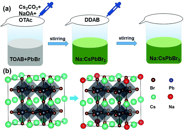
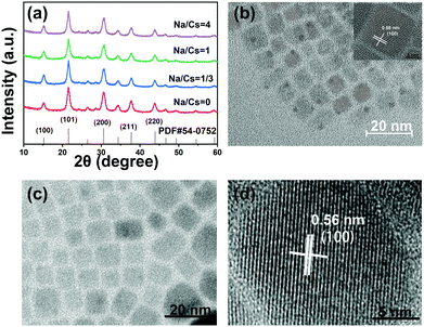
The Na+-doped CsPbBr3 QDs with different Na/Cs ratios (0, 1/3, 1 and 4) were prepared via a facile room-temperature synthesis method under ambient conditions, as shown in Fig. 1a. Different from the traditional method, in which oleic acid and oleylamine are used as ligands, here, OTAc and DDAB served as ligands, and NaOA, Cs2CO3 and PbBr2 provided Na+, Cs+, Pb2+ and Br− for the preparation of Na+-doped CsPbBr3 QDs. Detailed procedures for the QD fabrication are described in the Experimental Section. To elucidate the atomic coordination and occupancy parameters of the sodium ion within the cubic perovskite lattice, we performed supplementary density functional theory (DFT) calculations in which various substitution sites of sodium were considered, and adopted the Perdew–Burke–Ernzerhof (PBE) functional for the exchange–correlation interactions between the valence electrons. The force and energy convergence thresholds were set to −0.03 eV Å−1 and 10−6 eV, respectively. For the 2 × 2 × 2 supercell calculations, we used the same convergence thresholds (cutoff energy of 300 eV). As shown in Fig. S1 in the ESI,† the formation energies for the sodium substituted on the Cs site, vacancy site, Pb site and Br site are −1.57 eV, −6.66 eV, −1.88 eV, and 2.12 eV, respectively. The smallest formation energy appears at the sodium substituted on the Cs site. We can conclude that only when the Cs site is substituted by sodium can the perovskite cubic structure exist as the most stable state. Fig. 1b depicts a schematic illustration of a perovskite CsPbBr3 crystal after the substitution of Cs+ with smaller Na+ ions. Because the Na+ ions are smaller than Cs+, lattice contraction emerged after the partial substitution of Cs+ ions by Na+ ions.The XRD patterns of the Na+-doped CsPbBr3 QDs with different Na/Cs ratios are shown in Fig. 2a. All diffraction peaks can be readily identified in the XRD patterns of the CsPbBr3 QDs, indicating that the crystal structure of these QDs corresponds to the cubic phase (PDF#54-0752). Additionally, it is readily observed that no impurity peaks can be found in the XRD patterns of the Na+-doped CsPbBr3 QDs, revealing the intact crystalline nature of the QDs prepared at different doping concentrations and indicating that the Na+ doping does not affect the crystalline structure of the CsPbBr3 hosts. The morphology characterization of the undoped and doped CsPbBr3 QDs was carried out via TEM measurements. Fig. 2b shows that the as-prepared CsPbBr3 QDs display a cubic shape with a uniform size. The inset of Fig. 2b is the high-resolution TEM (HRTEM) image of a single CsPbBr3 QD, which reveals that its interplanar distance of 0.58 nm is highly consistent with the (100) plane of cubic-phase CsPbBr3 QDs. Fig. 2c displays the TEM image of the as-synthesized Na+-doped CsPbBr3 QDs (Na/Cs = 1/3). The cubic morphology of the doped QDs is similar to that of the undoped CsPbBr3 QDs. Excellent dispersion and a uniform size distribution are also observed for the Na+-doped QDs. The HRTEM image reveals that the as-synthesized doped QDs have clearly observable crystal lattices with an interplanar distance of 5.6 Å (Fig. 2d). The interplanar distance reduction can be ascribed to the lattice shrinkage caused by the substitution of smaller Na+ ions for larger Cs+ ions.
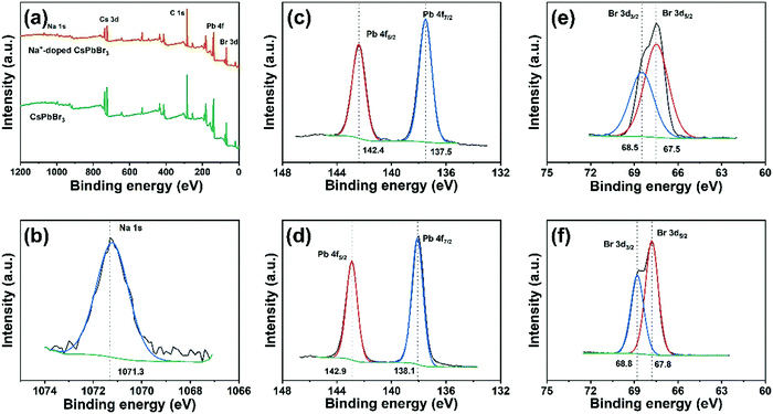
To further confirm that the sodium ions are introduced into the crystal lattice, a sample of CsPbBr3 and the Na+-doped QDs (Na/Cs = 1/3) were analyzed using XPS measurements. As shown in Fig. 3a, the XPS survey spectrum of the Na+-doped CsPbBr3 QDs clearly depicts signals of the elements Na, Cs, Pb and Br. As expected, the small binding energy peaks at 1071.3 eV shown in Fig. 3b correspond to the Na 1s signal, which is detected only in the Na+-doped CsPbBr3 QDs.32,33 This suggests that Na+ enters the CsPbBr3 lattice and retains the Na+ state. No differences are observed for the Cs 3d3/2 and Cs 3d5/2 signals in the XPS spectra of the Na+-doped and undoped CsPbBr3 QDs (Fig. S2, ESI†). Interestingly, compared to those of the undoped QDs, the Pb 4f5/2 and Pb 4f7/2 peaks of the Na+-doped QDs are shifted 0.5 eV, and the Br 3d3/2 and 3d5/2 peaks are shifted 0.3 eV. These results indicate changes in the chemical environment after Na+ ion doping, further demonstrating that the Na+ ions partially replace the Cs+ ionic sites through doping reactions.
Samples with different Na+ ion concentrations (Na/Cs = 0, 1/3, 1, 4) were prepared to investigate the optical properties of the Na+-doped CsPbBr3 QDs. As shown in the PL spectra in Fig. 4a, the PL peaks are located in the range of 520–533 nm. Closer inspection reveals that the PL peaks of the Na+-doped CsPbBr3 QDs blue-shift very slightly from 526 nm to 520 nm as the Na/Cs molar ratio is increased from 0 to 1. With further increasing the Na/Cs molar ratio to 4, the PL spectrum shifts to the right, implying that the PL is split, and the emission of the CsPbBr3 QDs dominates the spectrum. Fig. 4b shows the absorbance spectra of the CsPbBr3 QDs for the different Na+ doping concentrations. With increasing Na+ ion ratio, the absorption edges of the Na+-doped CsPbBr3 QDs maintain almost the same energy, which indicates that the doping of Na+ ions has a slight effect on the bandgap of CsPbBr3 QDs. For a more detailed comparison of the variation in the PLQY with different sodium ion concentrations, as shown in Fig. 4c. It can be found that with increasing sodium concentration (Na/Cs = 0–4), the PLQY first increases and then decreases. At a Na/Cs ratio of 1/3, the maximum PLQY of 94.74% was achieved, which was 1.22 times larger than that of fresh CsPbBr3 QDs. However, when the Na/Cs ratio reaches 4/1, the PLQY drops severely to 55.7%. The reason for this phenomenon can be explained as follows: excessive Na+ ions could lead to an increase in defects, thus increasing non-radiative recombination. The relevant photographs of the perovskite QDs with different doping concentrations under daylight and UV light are shown in Fig. S4 (ESI†).
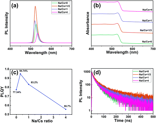 | ||
| Fig. 4 (a) PL spectra (excited by 365 nm light), (b) absorption spectra, (c) PLQY data, and (d) time-resolved PL decay curves of CsPbBr3 and Na+-doped CsPbBr3 QDs. | ||
Stability experiments for the doped and undoped perovskite QDs were conducted. Firstly, to evaluate the stability related to water resistance, the sodium-ion-doped and undoped perovskite QDs were dispersed in a mixed solution of water and n-hexane and stirred for 90 min. Color variations for both samples were recorded. As illustrated in Fig. S5 (ESI†), the bright emission for both the undoped and doped QDs dropped with increasing storage time. However, the emission of the undoped QDs completely disappeared after 90 min of stirring, demonstrating that sodium-ion-doping could enhance the water stability of the perovskite quantum dots to some extent. We also investigated the emission of films of the doped and undoped perovskite QDs; both were annealed at 120 °C under atmospheric conditions. As shown in Fig. S6 (ESI†), when the undoped QD film was annealed for 100 min, its emission intensity was obviously decreased. The emission intensity of the doped QD film decreased only a little. Specifically, after annealing for nearly 300 minutes, the brightness of the undoped sample is significantly lower than that of the doped sample. This result proves that the doped sample shows better thermal stability than the undoped one.
The time-resolved PL decays of the CsPbBr3 QDs and Na+-doped CsPbBr3 QDs were measured under an identical excitation wavelength of 375 nm (Fig. 4d). A tri-exponential relation can be chosen to fit the decay lifetimes of the above samples:
| A(t) = A1exp(−t/τ1) + A2exp(−t/τ2) + A3exp(−t/τ3) | (1) |
Here, A1, A2, A3 and τ1, τ2, τ3 are the weights and lifetime constants, respectively, of the multiple exponential functions used for analyzing the emission lifetimes. The average lifetime (τave) can be calculated by:
| τave = (A1τ12 + A2τ22 + A3τ32)/(A1τ1 + A2τ2 + A3τ3) | (2) |
The average lifetime for the excitonic luminescence of the pure CsPbBr3 QDs is 25.6 ns. It is found that the average PL decay lifetime becomes longer (31.2 ns) as the Na/Cs molar ratio is increased to 1/3. The average PL lifetime then decreases regularly with increased Na doping concentration. Concretely, the calculated result for Na/Cs = 1 is 28.5 ns, and that for Na/Cs = 4 is 22 ns; this reduction in PL decay indicates that the non-radiative recombination increases. The radiative and non-radiative decay rates can also be calculated using the following equations:
 | (3) |
 | (4) |
The radiative recombination rate and non-radiative recombination rates are summarized in Table 1. It is found that the maximum radiative recombination rate reaches 30.4 μs−1 for the Na+-doped CsPbBr3 QDs with a Na/Cs ratio of 1/3. This corresponds to the shortest non-radiative recombination rate (1.68 μs−1). All these results suggest that Na+ ion doping can control the non-radiative recombination and promote luminescence efficiency, which directly dominates the QLED device performance.
| Na/Cs | τ ave (ns) | PLQY (%) | η rad (μs−1) | η non-rad (μs−1) |
|---|---|---|---|---|
| 0 | 25.6 | 77.34 | 30.2 | 8.8 |
| 1/3 | 31.2 | 94.74 | 30.4 | 1.6 |
| 1 | 28.5 | 83.2 | 29.2 | 5.9 |
| 4 | 22 | 55.7 | 25.3 | 20.1 |
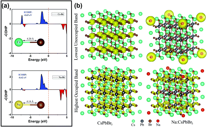
To further clarify the roles of the Na+ ion doping in the lattice structure and luminescence efficiency, we performed related auxiliary density functional theory (DFT) calculations. The projected crystal orbital Hamilton population (COHP) bonding analysis shown in Fig. 5a confirms that the Na–Br bonds in cubic CsPbBr3 are slightly more stable, by ca. 0.23 eV, than the Cs–Br bonds, with integrated COHP values of −0.65 and −0.42 eV. Additionally, the Cs–Br bond length (4.20 Å) is slightly longer than the Na–Br one (4.14 Å), indicating the lattice shrinkage caused by the substitution of smaller Na+ ions for larger Cs+ ions. This conclusion is highly consistent with the experimental results from XRD and high-resolution TEM. The calculated Cs–Br band distance was slightly larger than in the experimentally determined single crystal structure of CsPbBr3 (3.67–3.79 Å), mainly because we performed the standard DFT and employed the Perdew–Burke–Ernzerhof (PBE) exchange–correlation functional, which generally underestimates the gap value and overestimates the lattice constant.34 Additionally, the calculated model is based on the QD system, which also leads to differences from the single-crystal structure. As shown in Fig. 5b, the isosurfaces of the charge density of the highest occupied band and lowest unoccupied band in the CsPbBr3 and Na+-ion-doped CsPbBr3 QDs are very different. For the pure CsPbBr3, the lowest unoccupied band is strongly localized near the Pb2+ ions, while for the Na+-ion-doped CsPbBr3 QDs, it is localized around the Na+ ions, indicating that the doping of Na+ ions introduces a large number of electronic states in the lowest unoccupied orbital, leading to a reduction of defect states to some extent, which eventually induces the increase in the luminescence efficiency.
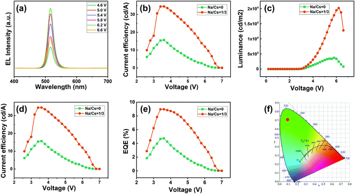
Inspired by the excellent properties of the Na+-doped CsPbBr3 QDs with an Na/Cs ratio of 1/3, we herein employed them for the fabrication of an EL QLED device; the pure CsPbBr3 QD-based device was adopted as the control device. A schematic illustration of the optimized device is presented in Fig. 6a. The as-fabricated device is composed of multiple layers in a regular sequence as follows: ITO/PEDOT:PSS/PTAA/QDs/TPBi/LiF/Al, where the PEDOT:PSS and PTAA serve as the hole transport injection layers, and TPBi plays the role of the electron injection layer. The flat-band energy level diagram of the device is shown in Fig. 6b; the energy levels associated with all the other materials were obtained from the literature.3Fig. 7a presents the measured EL spectra of the Na+-doped CsPbBr3 QD-based QLED device under different driving voltages. The EL spectra peaks are located at 516 nm with a narrow full width at half maximum of 22 nm and display a high color purity in the green range. Additionally, no change in the EL spectra is observed at different driving voltages, demonstrating that the QLED device exhibits excellent spectral stability. The current density–voltage and luminance–voltage characteristics of the QLEDs based on undoped and doped CsPbBr3 QDs are shown in Fig. 7b and c, respectively. It can be noted that the difference between the current density of the doped and undoped QD devices is not large. Additionally, the turn-on voltage of 2.5 V for the Na+-doped QD LED device is smaller than that of the control device (2.6 V) due to the enhanced electrical properties. The maximum luminance of the QLED with Na+-doped QDs is 20![[thin space (1/6-em)]](https://www.rsc.org/images/entities/char_2009.gif) 190 cd m−2, which is 5.4-fold higher than that of the LED fabricated with the undoped QDs under the same carrier injection, which implies that the device based on Na+-doped QDs has a higher electro-optic conversion efficiency. The current efficiency of the device based on the doped QDs exhibits a much higher peak value of 34.5 cd A−1 compared to that of the control device (15.6 cd A−1, Fig. 7d). Similarly, the maximum power efficiency for the Na+-doped QD-based device is 31.9 lm W−1 (Fig. S3, ESI†), which represents a more than 2.2-fold enhancement compared to the undoped-QD-based device. Accordingly, the best QLED device performance is achieved using the doped QDs, with a maximum EQE of 8.97% (Fig. 7e), which is a higher value than in previous reports of green QLED devices based on doped QDs. In addition, for the undoped CsPbBr3 QD-based QLED device, the luminance of the device at the peak efficiency of 4.74% is 676.4 cd m−2, and the EQE at the peak luminance of 3708 cd m−2 is 1.1%. For the Na+-doped QD-based QLED device, the luminance of the device at the peak EQE of 8.97% is 1475 cd m−2, and the EQE at the peak luminance of 20
190 cd m−2, which is 5.4-fold higher than that of the LED fabricated with the undoped QDs under the same carrier injection, which implies that the device based on Na+-doped QDs has a higher electro-optic conversion efficiency. The current efficiency of the device based on the doped QDs exhibits a much higher peak value of 34.5 cd A−1 compared to that of the control device (15.6 cd A−1, Fig. 7d). Similarly, the maximum power efficiency for the Na+-doped QD-based device is 31.9 lm W−1 (Fig. S3, ESI†), which represents a more than 2.2-fold enhancement compared to the undoped-QD-based device. Accordingly, the best QLED device performance is achieved using the doped QDs, with a maximum EQE of 8.97% (Fig. 7e), which is a higher value than in previous reports of green QLED devices based on doped QDs. In addition, for the undoped CsPbBr3 QD-based QLED device, the luminance of the device at the peak efficiency of 4.74% is 676.4 cd m−2, and the EQE at the peak luminance of 3708 cd m−2 is 1.1%. For the Na+-doped QD-based QLED device, the luminance of the device at the peak EQE of 8.97% is 1475 cd m−2, and the EQE at the peak luminance of 20![[thin space (1/6-em)]](https://www.rsc.org/images/entities/char_2009.gif) 190 cd m−2 is 2.75%. These excellent results indicated the high radiative recombination and effective electrical properties of the CsPbBr3 QDs after Na+ doping. The CIE chromaticity coordinates of (0.10,0.72) are almost at the edge of the CIE chart (Fig. 7f), demonstrating the high color purity of the Na+-doped QD-based device, and this device is thus especially suitable for wide-color-gamut display applications. The device performance is summarized in detail in Table S1 (ESI†). In addition, the performances of QLEDs based on CsPbBr3 perovskite QDs from the last six years were summarized and are shown in Table S2 in the ESI.† Although the EQE of the obtained QLED devices was not as high as that reported in other works in the literature, our work provides a new route for the development of the QLED performance.
190 cd m−2 is 2.75%. These excellent results indicated the high radiative recombination and effective electrical properties of the CsPbBr3 QDs after Na+ doping. The CIE chromaticity coordinates of (0.10,0.72) are almost at the edge of the CIE chart (Fig. 7f), demonstrating the high color purity of the Na+-doped QD-based device, and this device is thus especially suitable for wide-color-gamut display applications. The device performance is summarized in detail in Table S1 (ESI†). In addition, the performances of QLEDs based on CsPbBr3 perovskite QDs from the last six years were summarized and are shown in Table S2 in the ESI.† Although the EQE of the obtained QLED devices was not as high as that reported in other works in the literature, our work provides a new route for the development of the QLED performance.
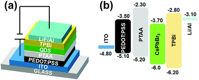 | ||
| Fig. 6 (a) A schematic illustration and (b) flat-band energy level diagram of the CsPbBr3 QLED device. | ||
4. Conclusions
In this study, we reported a simple and generalized doping strategy to obtain Na+-doped CsPbBr3 QDs for use in high-performance QLED devices. The as-prepared Na+-doped CsPbBr3 QDs displayed a characteristic morphology and phase structure very similar to those of their undoped counterpart, demonstrating that Na+ doping has no effect on the nucleation and growth of the CsPbBr3 QDs. Furthermore, the effects of Na+ doping on the optical and electrical properties were studied in detail. The optimized Na+-doped CsPbBr3 QDs have a PLQY value of 94.34%, a radiative recombination rate of 30.4 μs−1, and a longer lifetime of 31.2 ns. Consequently, the QLED device based on the Na+-doped CsPbBr3 QDs exhibited a maximum peak EQE of 8.79%, which is about 1.8-times higher than that of an undoped QD-based device. Correspondingly, the current efficiency is improved 2.2-fold from 15.6 cd A− to 34.5 cd A−1. These results show that Na+ doping represents a novel method to improve the performance of perovskite QLED devices.Author contributions
The manuscript was written through contributions from all authors. All of the authors have given approval to the final version of the manuscript.Conflicts of interest
There are no conflicts of interest to declare.Acknowledgements
This work was supported by the National Natural Science Foundation of China (No. 62104023), Doctor Research Start-up Funding of Chongqing University of Post and Telecommunications (E012A2020018), the Technology Innovation and Application Demonstration Key Project of Chongqing Municipality [cstc2019jszx-zdztzx0005], the Science and Technology Research Program of Chongqing Municipal Education Commission (Grant No. KJQN202100613, KJQN201900643), and Postdoctoral Project of Chongqing Science and Technology Bureau (cstc2021jcyj-bsh0250).References
- L. Protesescu, S. Yakunin, M. I. Bodnarchuk, F. Krieg, R. Caputo, C. H. Hendon, R. X. Yang, A. Walsh and M. V. Kovalenko, Nano Lett., 2015, 15, 3692 CrossRef CAS PubMed.
- Y. Hassan, J. H. Park, M. L. Crawford, A. Sadhanala, J. Lee, J. C. Sadighian, E. Mosconi, R. Shivanna, E. Radicchi, M. Jeong, C. Yang, H. Choi, S. H. Park, M. H. Song, F. D. Angelis, C. Y. Wong, R. H. Friend, B. R. Lee and H. J. Snaith, Nature, 2021, 591, 72 CrossRef CAS PubMed.
- J. Song, J. Li, L. Xu, J. Li, F. Zhang, B. Han, Q. Shan and H. Zeng, Adv. Mater., 2018, 30, 1800764 CrossRef PubMed.
- A. Dey, J. Ye, A. De, E. Debroye, S. K. Ha, E. Bladt, A. S. Kshirsagar, Z. Wang, J. Yin, Y. Wang, L. N. Quan, F. Yan, M. Gao, X. Li, J. Shamsi, T. Debnath, M. Cao, M. A. Scheel, S. Kumar, J. A. Steele, M. Gerhard, L. Chouhan, K. Xu, X. Wu, Y. Li, Y. Zhang, A. Dutta, C. Han, I. Vincon, A. L. Rogach, A. Nag, A. Samanta, B. A. Korgel, C. Shih, D. R. Gamelin, D. H. Son, H. Zeng, H. Zhong, H. Sun, H. V. Demir, I. G. Scheblykin, I. Mora-Seró, J. K. Stolarczyk, J. Z. Zhang, J. Feldmann, J. Hofkens, J. M. Luther, J. Pérez-Prieto, L. Li, L. Manna, M. I. Bodnarchuk, M. V. Kovalenko, M. B. J. Roeffaers, N. Pradhan, O. F. Mohammed, O. M. Bakr, P. Yang, P. Müller-Buschbaum, P. V. Kamat, Q. Bao, Q. Zhang, R. Krahne, R. E. Galian, S. D. Stranks, S. Bals, V. Biju, W. A. Tisdale, Y. Yan, R. L. Z. Hoye and L. Polavarapu, ACS Nano, 2021, 15, 10775 CrossRef CAS PubMed.
- J. Yao, J. Wang, J. Yang and H. Yao, Acc. Chem. Res., 2021, 54, 441–451 CrossRef CAS PubMed.
- J. Yao, J. Ge, K. Wang, G. Zhang, B. Zhu, C. Chen, Q. Zhang, Y. Luo, S. Yu and H. Yao, J. Am. Chem. Soc., 2019, 141, 2069–2079 CrossRef CAS PubMed.
- D. Lee, Y. Shin, H. J. Jang, J. Lee, K. Park, W. Lee, S. Yoo, J. Y. Lee, D. Kim, J. Lee and N. Park, ACS Energy Lett., 2021, 6, 1821 CrossRef CAS.
- A. Swarnkar, A. R. Marshall, E. M. Sanehira, B. D. Chernomordik, D. T. Moore, J. A. Christians, T. Chakrabarti and J. M. Luther, Science, 2016, 354, 92 CrossRef CAS PubMed.
- Y. He, M. Petryk, Z. Liu, D. G. Chica, I. Hadar, C. Leak, W. Ke, I. Spanopoulos, W. Lin, D. Y. Chung, B. W. Wessels, Z. He and M. G. Kanatzidis, Nat. Photonics, 2021, 15, 36 CrossRef CAS.
- H. Mao, C. Gu, S. Yan, Q. Xin, S. Cheng, P. Tan, X. Wang, F. Xiu, X. Liu, J. Liu, W. Huang and L. Sun, Adv. Electron. Mater., 2020, 6, 1900493 CrossRef CAS.
- T. Fang, T. Wang, X. Li, Y. Dong, S. Bai and J. Song, Sci. Bull., 2020, 66, 36 CrossRef.
- M. Liu, Q. Wan, H. Wang, F. Carulli, X. Sun, W. Zheng, L. Kong, Q. Zhang, C. Zhang, Q. Zhang, S. Brovelli and L. Li, Nat. Photonics, 2021, 15, 379 CrossRef CAS.
- J. Zito and I. Infante, Acc. Chem. Res., 2021, 54, 1554 CrossRef PubMed.
- J. Yang, Y. Song, J. Yao, K. Wang, J. Wang, B. Zhu, M. Yao, S. U. Rahman, Y. Lan, F. Fan and H. Yao, J. Am. Chem. Soc., 2020, 142, 2956–2967 CrossRef CAS PubMed.
- B. Han, S. Yuan, B. Cai, J. Song, W. Liu, F. Zhang, T. Fang, C. Wei and H. Zeng, Adv. Funct. Mater., 2021, 31, 2011003 CrossRef CAS.
- Y. Xu, Y. Cui, H. Yao, T. Zhang, J. Zhang, L. Ma, J. Wang, Z. Wei and J. Hou, Adv. Mater., 2021, 33, 2101090 CrossRef CAS PubMed.
- Q. Xiong, S. Huang, J. Du, X. Tang, F. Zeng, Z. Liu, Z. Zhang, T. Shi, J. Yang, D. Wu, H. Lin, Z. Luo and Y. Leng, Adv. Opt. Mater., 2020, 8, 2000977 CrossRef CAS.
- L. Schmidt, A. Pertegas, S. Gonzalez-Carrero, O. Malinkiewicz, S. Agouram, G. M. Espallargas, H. J. Bolink, R. E. Galian and J. Perez-Prieto, J. Am. Chem. Soc., 2014, 136, 850 CrossRef CAS PubMed.
- H. Huang, Q. Xue, B. Chen, Y. Xiong, J. Schneider, C. Zhi, H. Zhong and A. L. Rogach, Angew. Chem., Int. Ed., 2017, 5, 10947 Search PubMed.
- Q. Pan, H. Hu, Y. Zou, M. Chen, L. Wu, D. Yang, X. Yuan, J. Fan, B. Sun and Q. Zhang, J. Mater. Chem. C, 2017, 5, 10947 RSC.
- H. He, Y. Cui, B. Li, B. Wang, C. Jin, J. Yu, L. Yao, Y. Yu, B. Chen and G. Qian, Adv. Mater., 2019, 31, 1806897 CrossRef PubMed.
- J. Li, L. Xu, T. Wang, J. Song, J. Chen, J. Xue, Y. Dong, B. Cai, Q. Shan, B. Han and H. Zeng, Adv. Mater., 2017, 29, 1603885 CrossRef PubMed.
- Y. H. Kim, G. H. Lee, Y. T. Kim, C. Wolf, H. J. Yun, W. Kwon, C. G. Park and T. W. Lee, Nano Energy, 2017, 38, 51 CrossRef CAS.
- J. Pan, L. N. Quan, Y. Zhao, W. Peng, B. Murali, S. P. Sarmah, M. Yuan, L. Sinatra, N. M. Alyami, J. Liu, E. Yassitepe, Z. Yang, O. Voznyy, R. Comin, M. N. Hedhili, O. F. Mohammed, Z. H. Lu, D. H. Kim, E. H. Sargent and O. M. Bakr, Adv. Mater., 2016, 28, 8718 CrossRef CAS PubMed.
- Z. Hu, S. Liu, H. Qin, J. Zhou and X. Peng, J. Am. Chem. Soc., 2020, 142, 4254 CrossRef CAS PubMed.
- Y. Wang, C. Pu, H. Lei, H. Qin and X. Peng, J. Am. Chem. Soc., 2019, 141, 17617 CrossRef CAS PubMed.
- Y. Chen, Y. Liu and M. Hong, Nanoscale, 2020, 12, 12228 RSC.
- J. Yao, J. Ge, B. Han, K. Wang, H. Yao, H. Yu, J. Li, B. Zhu, J. Song, C. Chen, Q. Zhang, H. Zeng, Y. Luo and S. Yu, J. Am. Chem. Soc., 2018, 140, 3626–3634 CrossRef CAS PubMed.
- H. Kim, S. Bae, T. H. Lee, H. Lee, H. Kang, S. Park, H. W. Jang and S. Y. Kim, Adv. Funct. Mater., 2021, 31, 2102770 CrossRef CAS.
- M. T. Hoang, A. S. Pannu, C. Tang, Y. Yang, N. D. Pham, K. Gui, X. Wang, S. Yambem, P. Sonar, A. Du and H. Wang, Adv. Opt. Mater., 2020, 8, 2000742 CrossRef CAS.
- S. Zou, Y. Liu, J. Li, C. Liu, R. Feng, F. Jiang, Y. Li, J. Song, H. Zeng, M. Hong and X. Chen, J. Am. Chem. Soc., 2017, 139, 11443 CrossRef CAS PubMed.
- Y. Ji, M. Wan, Z. Yang, H. Qiu, S. Ji, J. Dou and N. V. Gaponenko, Nanoscale, 2020, 12, 6403–6410 RSC.
- S. Li, Z. Shi, F. Zhang, L. Wang, Z. Ma, D. Yang, Z. Yao, D. Wu, T. Xu, Y. Tian, Y. Zhang, C. Shan and X. Li, Chem. Mater., 2019, 31, 3917–3928 CrossRef CAS.
- W. Kohn and L. J. Sham, Phys. Rev., 1965, 140, 1133–1138 CrossRef.
Footnote |
| † Electronic supplementary information (ESI) available: Supporting Information is available from the Wiley Online Library or from the authors. See DOI: 10.1039/d1tc05997a |
| This journal is © The Royal Society of Chemistry 2022 |

