Natural textile based triboelectric nanogenerators for efficient energy harvesting applications†
Weradesh
Sangkhun
 and
Sompit
Wanwong
 *
*
Materials Technology Program, School of Energy, Environment and Materials, King Mongkut's University of Technology Thonburi, 126 Pracha Uthit Road, Bang Mod, Thung Khru, Bangkok 10140, Thailand. E-mail: sompit.wan@kmutt.ac.th
First published on 31st December 2020
Abstract
This work reports a facile method to create efficient natural textile based triboelectric nanogenerators (N-TENGs). First, plain natural textiles, cotton and silk, were dip-coated in cyanoalkyl silane and fluoroalkyl silane to transform their surface energy into positive and negative triboelectricity. The N-TENGs were fabricated by stacking an cyanoalkylated siloxane grafted fabric with an fluoralkylated siloxane grafted fabric to assemble a Cu fabric electrode. A single N-TENG generated a maximum output voltage and output current of 216.8 V and 50.3 μA (0.87 μA cm−2), without any nanopatterning. The double stacked N-TENG showed an enhanced output current of 84.8 μA (1.46 μA cm−2), and exhibited a maximum power output of 0.345 mW cm−2 at an external resistance of 0.42 MΩ. In addition, the N-TENG can light up 100 light-emitting diodes (LEDs) and charge capacitors, demonstrating its self-powering applications.
1. Introduction
Triboelectric nanogenerators (TENGs) are a promising class of self-powering supply sources that can simultaneously convert mechanical energy from human motion and nature into electrical power using a triboelectric effect and electrostatic induction between two dissimilar surfaces that have opposite tribopolarity.1–4 These make TENGs attractive for use in the portable and wearable electronics markets, where they are highly desirable for embedding in self-power devices for sport, fitness, medical sensing and health monitoring.5–9 A typical TENG is prepared using positive and negative triboelectric materials connected via electrode layers at the top and bottom. When a cyclical force is applied to the TENG, an output voltage and current are continuously generated. This triboelectric output relies on materials in the triboelectric series that dictate the power densities and surface roughness that can increase friction and contact area to improve the output performance.2,4,10,11Wang et al. reported the first TENG fabricated from a stack of different polymers, Kapton and polyethylene terephthalate (PET).12 Upon cyclic agitation, this TENG produced an ambient electrical output of 3.3 V and 0.6 μA, demonstrating its self-powering device applications. Polymer-based TENGs have been extensively explored.2,10,12–14 Some of these TENGs are stretchable and flexible and attain a high output performance, meaning that they can be potentially used as pressure sensor devices for medical and wearable electronic applications;15–19 however, one drawback is that the polymer does not feel like a wearable garment. Therefore, textiles have received attention to integrate them with TENGs because they are breathable, lightweight, flexible, shape adaptive, scalable and suitable to wear. Several approaches, such as nanopatterning and chemical modification, have been reported to transform various textiles into triboelectric materials.20–25 With proper design, textile-based TENGs can possibly convert all human motions such as walking, arm swinging and joint movements to power low consumption electronic devices. For examples, Liu et al. reported a TENG using crosslinked polyester terephthalate (PET) fabric and a polydimethylsiloxane (PDMS) coated carbon nanotube (CNT) sheet. The TENG is bendable and can generate an open circuit voltage (Voc) of 500 V and a power density of 153.8 mW m−2, which can light tens of light-emitting diodes (LEDs).26 While, a triple-stacked TNEG can double the open circuit voltage (Voc), and short circuit current (Isc) due to increased friction area. Hong et al. deposited aluminum nanoparticles on textile substrates in order to increase the friction area. The TENG attached on an arm sleeve produced a power density of 33.6 mW cm−2.27 Seung et al. grew ZnO nanorods on a commercial silver-coated textile followed by encapsulating it with PDMS. A high output voltage and current of 120 V and 65 μA were observed.28 Choi et al. employed a corrugated textile-based TENG consisting of silk fabric and Si-rubber (Ecoflex). This corrugated TENG produced a Voc of 28.13 V and Isc of 2.71 μA upon stretching and pressing motions.29 Kang et al. developed a folded elastic strip based TENG made from elastic strips of Al/PET and polytetrafluoroethylene (PTFE)/PET. A single strip TENG generated a Voc of 840 V, an Isc of 55 μA and a power of 7.33 mW.30 Kim et al. reported an electrospun silk fiber based TENG with a power output of 4.3 mW m−1.31 Daoud et al. fabricated a TENG using cashmere fabric treated with a surfactant, tween-20, and PTFE film. The TENG showed a 10-fold higher maximum power output compared to a pristine cashmere-based TENG.32
Another approach was carried out by grafting fluoroalkylsilane on textile substrates to change their surface energy to make them more negative. Guo et al. grafted fluoroalkysilane on a PDMS coated nylon–AgNWs textile (FPAN) and used it as a negative triboelectric layer. When assembling a TENG device with FPAN and PET cloth, the TENG exhibited a high Voc of 575 V and Isc of 12.1 μA.33 Andrew et al. tuned the surface energy of cotton to make it more negative by dipping it in fluoroalkylsilane solution. It was found that the fluoroalkylated siloxane-grafted cotton was chemically stable and its surface charge density was increased. Fluorinated cotton coupled with nylon cloth can increase outputs by around 3–5 times compared with a device fabricated from pristine cotton and nylon. The all-textile TENG provided an average power output of 13 μW cm−2.34 Recently, we developed methods to create a washable and oxidation resistive electrode based on poly(perfluorododecylacrylate) encapsulated Ag-cotton (PFDA-Ag-cotton). The conductive PFDA-Ag-cotton was used as top and bottom electrodes for a TENG device. The perfluoroalkylated siloxane (F-cotton) was used a negative triboelectric layer and PDMS was used as a positive triboelectric layer. The TENG produces a maximum Voc of 25 V and Isc of 2.25 μA.35
So far, many studies have mainly focused on coating fibers and textiles using PDMS and nanoparticles. However, these require multi-coating processes, complex procedures and special equipment, which limit their scalable production. In addition, most textile-based TENGs are based on synthetic fabrics such as polyester terephthalate (PET) and nylon,6,20,36 while natural fabrics that provide remarkable breathability over some artificial fabrics have been less explored.37 Thus, we are interested in utilizing natural textiles, including cotton and silk, as triboelectric substrates because they are abundant and have intrinsic functional groups on their surfaces.37,38 Cotton fiber contains a cellulose content of up to 90%,39 while silk fiber is composed of fibroin protein.40 Thus, the hydroxyl groups of the cellulose in cotton and silk protein can be reacted with silanes that have different polarities, leading to materials that have different surface energies and tribopolarities (positive or negative surfaces). Herein, we describe a facile method to transform cotton and silk into triboelectric materials. First, untreated commercial textiles, cotton and silk, were transformed into negative and positive materials by dipping them in fluoroalkylsilane and cyanoalkylsilane, respectively. The morphologies of the modified textiles were studied using scanning electron microscopy (SEM) and atomic force microscopy (AFM). The chemical surfaces of the silane grafted textiles were investigated using energy-dispersive X-ray (EDS) and X-ray photoelectron (XPS) spectroscopies. Next, the natural textile based TENGs (N-TENGs) were simply fabricated by gluing the fluoroalkylated textiles and cyanoalkylated textiles to conductive fabric electrodes. The N-TENGs were fabricated in single and double stacks using face-to-face configuration. The electrical properties of these materials including the output voltage, output current, power density, and surface charge density were examined. The external load matching of the TENG devices were also investigated. The energy harvesting performance was tested using LEDs connected in parallel and in the charging efficiency of capacitors.
2. Experimental section
2.1. Materials
Trichloro(1H,1H,2H,2H-perfluorooctyl) silane (97%) was purchased from TCI Japan. 3-Cyanopropyltriethoxysilane (98%) and graphite powder (<20 μm) were purchased from Sigma-Aldrich. Hexane, isopropyl alcohol and acetone were purchased from Fisher Scientific. Deionized (DI) water was purchased from Siam Beta, Thailand. Cotton fabric was purchased from Ann, Ltd, Thailand. Degummed Thai silk was obtained from Natural Niche Co, Ltd, Thailand. Copper fabric was purchased from Less EMF Inc. Conductive paint was purchased from Bare Conductive Ltd. Fabric adhesive glue was purchased from Vibra-Tite.2.2. Preparation of the triboelectric materials
All fabrics were cut into 3 × 3 inch2 pieces. All fabrics were cleaned by soaking them in detergent for 30 minutes and washing them with copious amounts of DI water before use.2.3. Fabrication of the triboelectric nanogenerator (TENG)
The triboelectric nanogenerator (TENG) was fabricated in a face-to-face configuration. Fluoroalkylated siloxane grafted fabric (F-fabric) and cyanoalkylated siloxane grafted fabric (CN-fabric) served as the negative and positive layers, respectively. Each triboelectric layer was attached to a copper (Cu) fabric electrode using conductive adhesive. Conductive silver (R = 6.4 Ω) and carbon inks (R = 55 Ω) were employed to make contact between the F-fabric and Cu fabric. In addition, conductive glue (R = 50 Ω), made by mixing graphite powder (GPs) with fabric glue (20 wt%), was applied between the CN and Cu fabrics using a doctor blade technique to enhance the contact quality and charge extraction ability of the device. Finally, the electrode was attached to the measuring wires using copper tape.2.4. Instrumentation
Conformal images and surface characterization of the fabric after silane treatment were characterized using SEM (JEOL JSM 6610 LV). EDS data were recorded on an Oxford INCA-xart. The surface morphologies and surface roughness of the modified textiles were characterized using an AFM (Park System NX10). The chemical state information of the modified fabric was determined using XPS (Kratos AXIS ULTRA). Contact angle measurements were conducted using a static optical contact angle meter (KINO SL150E). The voltage and current output of the TENGs were measured using an oscilloscope (RIGOL DS2102A) and a source meter (Keithley 2400), respectively.3. Results and discussion
3.1. Surface modification of the natural textiles
Fig. 1 shows the surface chemical modification of cotton and silk. The surface composition of plain cotton and silk were facilely transformed into negative and positive triboelectric materials by dipping them in trichloro(1H,1H,2H,2H-perfluorooctyl) silane (PFTS) and 3-cyanopropyltriethoxysilane (CTES) solutions, respectively. Since cotton is composed of cellulose and silk is composed of natural protein fiber, there are sufficient hydroxyl groups (–OH) in cellulose and silk protein to react with different alkylsilanes.41–43 After treating the cotton and silk with PFTS, droplets of water placed on the surface indicated that the fabric surface became water repellent. This suggests that the fluoroalkylated siloxane film was coated on the textile surface.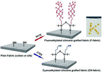 | ||
| Fig. 1 Schematic illustration of the surface chemical modification of natural textiles with different silanes and a photograph of droplets of water on F-cotton. | ||
3.2. Surface characterization of silane grafted fabrics
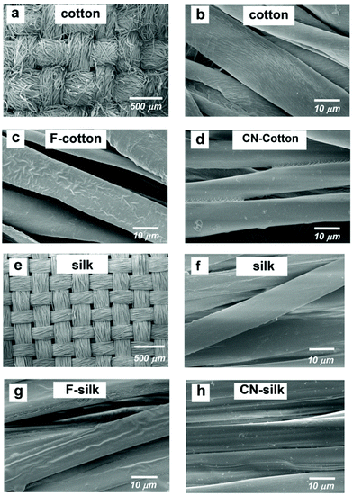
The surface morphologies of silane grafted cotton and silk were observed by SEM. Fig. 2 and 3 show the SEM images of cotton and silk before and after treatment with fluoroalkylsilane and cyanoalkylsilane. After treating the cotton with trichloro(1H,1H,2H,2H-perfluorooctyl) silane (F-cotton), the presence of fluoroalkyl siloxane film on the cotton fibers was clearly seen, as shown in Fig. 2c. Fig. 2d displays the cotton fibers after being treated with 3-cyanopropyltriethoxysilane (CN-cotton). The CN-cotton exhibits a thin film coating on and between its fibers. Fig. 2e and f show SEM images of plain silk. The fluoroalkyl siloxane deposited layer on silk fiber (F-silk) can be clearly seen (Fig. 2g). Fig. 2h shows an SEM image of cyanoalkyl siloxane coated on silk (CN-silk). In addition, the EDS spectra of all of the modified cotton and silk materials (Fig. S1, ESI†) show the presence of Si elements, which provides evidence of the deposition of siloxane on the fiber surfaces.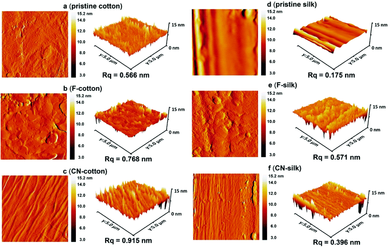 | ||
| Fig. 3 AFM topology and 3D images (5 × 5 μm) of (a) pristine cotton, (b) F-cotton, (c) CN-cotton, (d) pristine silk, (e) F-silk and (f) CN-silk. | ||
AFM analysis was conducted to investigate the topography and surface roughness of the pristine and modified textiles. Fig. 3a–c show a comparison between the AFM images of pristine cotton, F-cotton and CN-cotton. As observed in Fig. 3b, the topology of the F-cotton is covered with fluoroalkylated siloxane polymeric film. The surface roughness is 0.768 nm, which is higher than that of the untreated cotton (0.566 nm). Apparently, the CN-cotton exhibits the highest roughness of 0.915 nm (Fig. 3c). For the silk fabric, Fig. 3d shows that the roughness of pristine silk is quite smooth, with an root mean square roughness (Rq) value of 0.175 nm. For F-silk and CN-silk, the roughness of the modified silk increased to 0.571 and 0.396 nm, respectively (Fig. 3e and f).
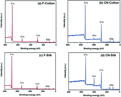
Next, the chemical state information of the silane grafted textiles was determined using XPS. The F-cotton shows an F 1s peak at 687.7 eV and an O 1s peak at 531.3 eV (Fig. 4a). The C 1s peak (290.79 eV) is split into two peaks (286 and 288 eV) because of the interaction between the fluorine and carbon atoms.34,35 This result confirms that fluoroalkyl was successfully grafted on the cotton. The CN-cotton exhibits an O 1s peak at 532 eV, N 1s peak at 400 eV, C 1s peak at 285 eV and Si 2p at 103 eV, respectively (Fig. 4b). The F-silk shows an F 1s peak at 687.8 eV and an O 1s peak at 532.8 eV (Fig. 4c). Similar to the F-cotton, the C 1s peak of the F-silk also exhibits two peaks, at 291.5 and 286 eV. The CN-silk shows an O 1s peak at 532.5 eV, N 1s peak at 400.5 eV, C 1s peak at 285.5 eV and Si 2p at 103 eV, respectively (Fig. 4d). All of the XPS spectra show the presence of Si, which confirms the siloxane coating on the fabric fibers. In addition, the relative atomic % of Si in the fluoroalkylated fabrics is 5.6% for the F-cotton and 5.9% for the F-silk (Table S1†). The % of F in the F-cotton and F-silk are also similar (in the range of 62–64%). These indicate that both cotton and silk contain a similar density of fluoroalkylated siloxane. Whereas, CN-cotton and CN-silk have Si % of 8% and 14%, respectively. This suggests that CN-silk contains a higher density of cyanoalkylated siloxane.
3.3. N-TENGs
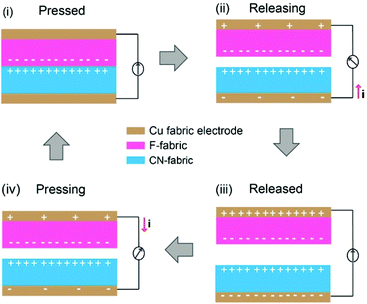
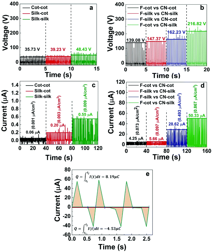
The N-TENGs were fabricated in a face-to-face configuration using the F-fabric and CN-fabric as triboelectric layers. Copper fabric was used as the top and the bottom electrodes. According to the triboelectric series,10,44–46 a fluorinated surface is one of the most negative materials because of the strong attractive force of the electrons of the fluorine atoms, thus the F-fabric served as the negative triboelectric layer, while CN-fabric served as a complementary positive triboelectric layer. When the N-TENG was periodically tapped by hand, the F-fabric and CN-fabric were brought into pressed and released states. Upon pressing, full contact between the F-fabric and CN-fabric induced surface charge transfer at the interface. The negative charges from the CN-fabric transfer to the F-fabric, inducing a positively charged surface. On the contrary, the F-fabric accumulated negative charge on its surface. Due to the different surface potentials of each triboelectric layer, inductive current flowed through the device. Upon release, an inductive current flowed back to each layer to maintain their equilibrium state (Fig. 5).2,20,34To systematically investigate the triboelectric output of the N-TENGs, devices denoted as F-cot/CN-cot, F-silk/CN-silk, F-cot/CN-silk, F-silk/CN-cot and pristine-TENGs were fabricated. Fig. 6 depicts the corresponding electrical outputs of the N-TENGs upon cyclic hand beating (force ∼2 N). It should be noted that the output voltages of the pristine TENGs are higher than those reported in the literature. This is due to the type of adhesive material used to bond the plain fabric and Cu fabric electrode (for more details see the ESI, Fig. S2†). The electrical outputs of the silane modified N-TENGs were significantly higher than those of pristine cotton and pristine silk. The materials have average output voltages and output currents in the following order; F-cot/CN-silk > F-silk/CN-cot > F-silk/CN-silk > F-cot/CN-cot (Fig. 6c and d). In addition, the surface charge or transferred charge is calculated from the integration of the current signal over time32,47,48 (Fig. 6e). For the F-cot/CN-silk TENG, the average surface charge under the pressing and releasing states of the three movement cycles are 8.19 μC (0.141 μC cm−2) and 4.53 μC (0.078 μC cm−2), indicating that charge transfer in the opposite direction is not equal. This may contribute to the retardation between the charge transfer cycle and periodic movement of the device,48 and the bottom adhesive layer (fabric glue/graphite) acts as a double layer capacitance and promotes the charge restoration layer during the releasing state.49
Interestingly, N-TENGs fabricated from a cross combination of the modified cotton and silk significantly provided higher electrical outputs than those of N-TENGs fabricated from same type of textile (F-cot/CN-cot or F-silk/CN-silk). Since cotton and silk are woven fabrics, there are many voids between the weft and warp yarns that inevitably cause air breakdown and diminish their surface charge densities.50–52 In our case, we think that the cross combination of F-cot/CN-silk and F-silk/CN-cot may coincidentally promote the overlapping of the interface and reduce the air breakdown between the voids of the textiles under the pressing conditions.
Notably, the combination of F-cot/CN-silk exhibited the highest electrical output, of 216.8 V and 50.3 μA (0.87 μA cm−2). This enhanced electrical performance can be explained according to the surface morphology, hydrophobicity and chemical composition of the material. In this regard, the AFM results reveal that the surface roughness of the F-cotton (Rq = 0.768 nm) is higher than that of the F-silk (Rq = 0.571 nm), suggesting that the F-cotton has a higher friction area.53–55 Moreover, it was found that the apparent water contact angle of the F-cotton and F-silk are 146° and 135°, respectively (Fig. S2†). Since the XPS results show that the F-cotton and F-silk have similar fluorine density (Table S1†), the difference in the water contact angles can be mainly attributed to the surface roughness of the F-fabric. The hydrophobic effect is known to influence the electrical output of TENGs.44,53,56 More hydrophobic surfaces tend to increase the charge separation and charge accumulation of TENGs.41,44,53,56,57 Thus, in our case, F-cotton is considered to be a better negative triboelectric material because of its synergistically enhanced surface roughness and hydrophobicity, leading to an enhancement in its surface charge density. For the CN-fabric, the XPS results show that the % Si content of the CN-silk is double that of the CN-cotton (Table S1†). Thereby, the large number of cyanoalkyl groups on the CN-silk fibers attracts more charge from the F-fabric. Besides this, the atomic N % of the CN-silk is higher than that of the CN-cotton because the silk fiber is composed of amino protein (NH2), while cotton fiber is composed of cellulose (OH). According to the literature in which the correlation between the chemical composition and tribopolarity is studied, the NH2 group is a stronger electron donating group compared to the OH group.45,57–61 This suggests that the CN-silk should have a more positive surface than the CN-cotton. Thus, a material with a high surface roughness (for example, CN-cotton) does not always exhibit impressive triboelectric performance. This suggests that the surface roughness and chemical grafting density of the TENG substrates should be optimized.
3.4. Double stacked N-TENGs
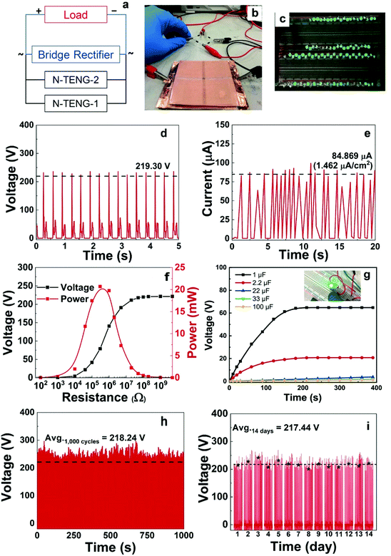
Fig. 7a shows a circuit diagram of double stacked TENGs fabricated from F-cotton and CN-silk. The top and bottom of the device were connected to a rectifier and an external load (Fig. 7b). Under an applied cycle of mechanical tapping, a maximum voltage of 219.30 V and a maximum current of 84.87 μA (1.46 μA cm−2) were observed (Fig. 7d and e). The output current was increased by around 1.7 times compared to that of the single N-TENG device (50.3 μA, 0.87 μA cm−2). The N-TENGs were connected to LEDs without any energy storage system. Under external pushing forces such as hand tapping, the double stacked N-TENG can directly light 100 LEDs connected in series (Fig. 7c and Video S1†). This demonstrates that our TENGs can be potentially used as a power supply source. To optimize the performance of the TENG devices, external load-dependent outputs of the TENGs were determined using variable resistors from 100 Ω–5 GΩ. The resistance-dependent output voltage versus current density was plotted (Fig. 7f). The voltage increased with an increase in the resistance, and as a result, the calculated power density of the TENG62 reached a maximum value of 0.345 mW cm−2 at an external resistance of 0.42 MΩ. Next, the charging behavior of the double stacked N-TENG was explored using five capacitors ranging from 1 to 100 μF (a circuit diagram is shown in Fig. S4†). Fig. 7g shows that a 1 μF capacitor can reach a saturation voltage of 60 V within 150 s, while larger capacitors exhibit linear charging behavior. We also demonstrated that an LED can be continuously lighted using a charged capacitor (Video S2†).In addition, the stability of N-TENGs is important for their practical applications. Fig. 7h shows the output voltages of the N-TENG after periodically tapping 1000 cycles and Fig. 7i illustrates the long term operation of the N-TENG for 14 days. It was found that the initial and final output voltages are similar in value (up to 200 V), suggesting that the active surfaces of the N-TENG are stable and durable under mechanical forces and ambient conditions. Besides this, from our previous work and the literature,34,35,63 the silane functionalized fabrics are chemically stable and robust under machine washing, sonication and in detergent. Thus, our triboelectric materials can be reused after cleaning.
4. Conclusion
In summary, we successfully functionalized plain cotton and silk with different silanes to create negative and positive triboelectric textiles. The best N-TENG achieved from F-cot/CN-silk provided an output voltage of 219 V and an output current of 50.3 μA (0.87 μA cm−2). The double stacked N-TENG doubled the output current, with a maximum power density of 0.345 mW cm−2 at an external resistance of 0.42 MΩ. This energy was sufficient to light up 100 LEDs and charge capacitors. These demonstrated that the N-TENG can be potentially used as a self-powering source for small electronics.Conflicts of interest
There are no conflicts to declare.Acknowledgements
The authors acknowledge the financial support provided by The Asahi Glass Foundation, Japan. This work is also partially funded by the Grant for New Researchers, from the National Research Council of Thailand (NRCT), grant no. NRCT5-TRG63005-03.References
- Z. L. Wang, G. Zhu, Y. Yang, S. H. Wang and C. F. Pan, Mater. Today, 2012, 15, 532–543 CrossRef CAS
.
- Z. L. Wang, J. Chen and L. Lin, Energy Environ. Sci., 2015, 8, 2250–2282 RSC
.
- Z. L. Wang and W. Z. Wu, Angew. Chem., Int. Ed., 2012, 51, 11700–11721 CrossRef CAS
.
- F. R. Fan, W. Tang and Z. L. Wang, Adv. Mater., 2016, 28, 4283–4305 CrossRef CAS
.
- A. K. Yetisen, H. Qu, A. Manbachi, H. Butt, M. R. Dokmeci, J. P. Hinestroza, M. Skorobogatiy, A. Khademhosseini and S. H. Yun, ACS Nano, 2016, 10, 3042–3068 CrossRef CAS
.
- Z. M. Lin, J. Yang, X. S. Li, Y. F. Wu, W. Wei, J. Liu, J. Chen and J. Yang, Adv. Funct. Mater., 2017, 28, 1704112 CrossRef
.
- Q. Zhang, Z. Zhang, Q. J. Liang, F. F. Gao, F. Yi, M. Y. Ma, Q. L. Liao, Z. Kang and Y. Zhang, Nano Energy, 2019, 55, 151–163 CrossRef CAS
.
- H. Wu, Y. Haung, F. Xu, Y. Duan and Z. Yin, Adv. Mater., 2016, 28, 9881–9919 CrossRef CAS
.
- J. Li, R. Bao, J. Tao, Y. Peng and C. Pan, J. Mater. Chem. C, 2018, 11878–11892 RSC
.
- D. W. Kim, J. H. Lee, J. K. Kim and U. Jeong, NPG Asia Mater., 2020, 12, 6 CrossRef
.
- S. S. K. Mallineni, H. Behlow, Y. C. Dong, S. Bhattacharya, A. M. Rao and R. Podila, Nano Energy, 2017, 35, 263–270 CrossRef CAS
.
- F. R. Fan, Z. Q. Tian and Z. L. Wang, Nano Energy, 2012, 1, 328–334 CrossRef CAS
.
- Z. L. Wang, Adv. Mater., 2012, 24, 280–285 CrossRef CAS
.
- G. Zhu, C. Pan, W. Gao, C. Y. Chen, Y. Zhou, R. Yu and Z. L. Wang, Nano Lett., 2012, 12, 4960–4965 CrossRef CAS
.
- P. K. Yang, L. Lin, F. Yi, X. Li, K. C. Pradel, Y. Zi, C. Wu, J. H. He, Y. Zhang and L. W. Zhong, Adv. Mater., 2015, 27, 3817–3824 CrossRef CAS
.
- P. K. Yang, Z. H. Lin, K. C. Pradel, L. Lin, X. Li, X. Wen, J. H. He and Z. L. Wang, ACS Nano, 2015, 9, 901–905 CrossRef CAS
.
- J. Y. Tseng, L. Lee, Y. C. Huang, J. Chang, H. T. Y. Su, Y. C. Shih, H. W. Lin and Y. L. Chueh, Small, 2081, 1800541, 1–8 Search PubMed
.
- Y. Ai, T. H. Hsu, D. C. Wu, L. Ling, J. H. Chen, Y. Z. Chen, S. C. Wu, C. Wu, Z. M. Wang and Y. L. Chueh, J. Mater. Chem. C, 2018, 6, 5514–5512 RSC
.
- Y. Liu and C. Hu, Nanoscale, 2020, 12, 20118–20130 RSC
.
- J. Q. Xiong and P. S. Lee, Sci. Technol. Adv. Mater., 2019, 20, 837–857 CrossRef
.
- W. Paosangthong, R. Torah and S. Beeby, Nano Energy, 2019, 55, 401–423 CrossRef CAS
.
- J. D. Shi, S. Liu, L. S. Zhang, B. Yang, L. Shu, Y. Yang, M. Ren, Y. Wang, J. W. Chen, W. Chen, Y. Choi and X. M. Tao, Adv. Mater., 2019, 32, 1901958 CrossRef
.
- G. R. Chen, Y. Z. Li, M. Bick and J. Chen, Chem. Rev., 2020, 120, 3668–3720 CrossRef CAS
.
- X. Tao, Acc. Chem. Res., 2019, 52, 307–315 CrossRef CAS
.
- W. Weng, P. Chen, S. He, X. Sun and H. Peng, Angew. Chem., Int. Ed., 2016, 55, 6140 CrossRef CAS
.
- L. M. Liu, J. Pan, P. N. Chen, J. Zhang, X. H. Yu, X. Ding, B. J. Wang, X. M. Sun and H. S. Peng, J. Mater. Chem. A, 2016, 4, 6077–6083 RSC
.
- S. Lee, W. Ko, Y. Oh, J. Lee, G. Baek, Y. Lee, J. Sohn, S. Cha, J. Kim, J. Park and J. Hong, Nano Energy, 2015, 12, 410–418 CrossRef CAS
.
- W. Seung, M. K. Gupta, K. Y. Lee, K. S. Shin, J. H. Lee, T. Y. Kim, S. Kim, J. Lin, J. H. Kim and S. W. Kim, ACS Nano, 2015, 9, 3501–3509 CrossRef CAS
.
- A. Y. Choi, C. J. Lee, J. Park, D. Kim and Y. T. Kim, Sci. Rep., 2017, 7, 45583 CrossRef CAS
.
- Y. Kang, B. Wang, S. G. Dai, G. L. Liu, Y. P. Pu and C. G. Hu, ACS Appl. Mater. Interfaces, 2015, 7, 20469–20476 CrossRef CAS
.
- H. J. Kim, J. H. Kim, K. W. Jun, J. H. Kim, W. C. Seung, O. H. Kwon, J. Y. Park, S. W. Kim and I. K. Oh, Adv. Energy Mater., 2016, 6, 1502329 CrossRef
.
- L. Y. Wang, X. Y. Yang and W. A. Daoud, J. Mater. Chem. A, 2018, 6, 11198–11204 RSC
.
- Y. B. Guo, K. R. Li, C. Y. Hou, Y. G. Li, Q. H. Zhang and H. Z. Wang, ACS Appl. Mater. Interfaces, 2016, 8, 4676–4683 CrossRef CAS
.
- L. S. Zhang, Y. H. Yu, G. P. Eyer, G. Q. Suo, L. A. Kozik, M. Fairbanks, X. D. Wang and T. L. Andrew, Adv. Mater. Technol., 2016, 1, 1600147 CrossRef
.
- S. Wanwong, W. Sangkhun, S. Z. Homayounfar, K. W. Park and T. L. Andrew, RSC Adv., 2019, 9, 9198–9203 RSC
.
- Z. Zhang, Y. Chen, D. K. Debeli and J. S. Guo, ACS Appl. Mater. Interfaces, 2018, 10, 13082–13091 CrossRef CAS
.
- F. Ahmad, H. S. Choi and M. K. Park, Macromol. Mater. Eng., 2015, 300, 10–24 CrossRef CAS
.
- K. L. Pickering, M. G. A. Efendy and T. M. Le, Composites, Part A, 2016, 83, 98–112 CrossRef CAS
.
-
Y. L. Hsieh, Chemical structure and properties of cotton, in Cotton, ed. S. Gordon and Y. L. Hsieh, Woodhead Publishing, 2007, pp. 3–34, DOI:10.1533/9781845692483.1.3
.
- M. R. Buga, C. Zaharia, M. Balan, C. Bressy, F. Ziarelli and A. Margaillan, Mater. Sci. Eng., C, 2015, 51, 233–241 CrossRef CAS
.
- X. J. Li, L. Q. Zhang, Y. G. Feng, X. L. Zhang, D. A. Wang and F. Zhou, Adv. Funct. Mater., 2019, 29, 1903587 CrossRef
.
- T. Makowski, Cellulose, 2020, 27, 1–9 CrossRef CAS
.
- S. Roy, H. U. Ko, P. Maji, L. V. Hai and J. Kim, Chem. Eng. J., 2020, 385, 123723 CrossRef
.
- S. H. Shin, Y. H. Kwon, Y. H. Kim, J. Y. Jung, M. H. Lee and J. Nah, ACS Nano, 2015, 9, 4621–4627 CrossRef CAS
.
- S. H. Shin, Y. E. Bae, H. K. Moon, J. Kim, S. H. Choi, Y. Kim, H. J. Yoon, H. M. Lee and J. Nah, ACS Nano, 2017, 11, 6131–6138 CrossRef CAS
.
- J. Y. Kim, J. Lee, S. Park, C. Park, C. Park and H. J. Choi, RSC Adv., 2017, 7, 49638–493773 Search PubMed
.
- H. Zhang, Y. Lu, A. Ghafferinejad and P. Basset, Nano Energy, 2018, 51, 10–18 CrossRef CAS
.
- H. Zhang, S. Feng, D. He, P. Molinie and J. Bai, Nano Energy, 2019, 63, 103856 CrossRef CAS
.
- H. Ji, X. Zhao, Z. Qiao, J. Jung, Y. Zhu, Y. Lu, L. L. Zhang, A. H. MacDonald and R. S. Ruoff, Nat. Commun., 2014, 5, 3317 CrossRef
.
- Y. Liu, W. Liu, Z. L. Wang, W. He, Q. Tang, Y. Xi, X. Wang, H. Guo and C. Hu, Nat. Commun., 2020, 11, 1–8 CAS
.
- W. He, W. Liu, J. Chen, Z. Wang, Y. Liu, X. Pu, H. Yang, Q. Tang, H. Yang, H. Guo and C. Hu, Nat. Commun., 2020, 11, 4277 CrossRef CAS
.
- J. Wang, C. Wu, Y. Dai, Z. Zhao, A. Wang, T. Zhang and Z. L. Wang, Nat. Commun., 2017, 8, 88 CrossRef
.
- H. Y. Li, L. Su, S. Y. Kuang, C. F. Pan, G. Zhu and Z. L. Wang, Adv. Funct. Mater., 2015, 25, 5691–5697 CrossRef CAS
.
- R. D. I. G. Dharmasena and S. R. P. Silva, Nano Energy, 2019, 62, 530–549 CrossRef CAS
.
- X. Cheng, B. Meng, X. Chen, M. Han, H. Chen, Z. Su, M. Shi and H. Zhang, Small, 2016, 2, 229–236 CrossRef
.
- K. Y. Lee, J. Chung, J. H. Lee, K. N. Kim, N. R. Kang, J. Y. Kim, M. H. Kim, K. S. Shin, M. K. Gupta, M. J. Baik and S. W. Kim, Adv. Mater., 2014, 26, 5037–5042 CrossRef CAS
.
- Y. Liu, J. Mo, Q. Fu, Y. Lu, N. Zhang, S. Wang and S. Nie, Adv. Funct. Mater., 2020, 2004714, 1–33 Search PubMed
.
- G. Song, Y. Kim, S. Yu, M. O. Kim, S. H. Park, S. M. Cho, D. B. Velusamy, S. H. Cho, K. L. Kim, J. Kim, E. Kim and C. Park, Chem. Mater., 2015, 27, 4749–4745 CrossRef CAS
.
- K. E. Byun, Y. Cho, M. Seol, S. Kim, S. W. Kim, H. J. Shin and S. Hwang, ACS Appl. Mater. Interfaces, 2016, 8, 18519–18525 CrossRef CAS
.
- A. F. Diaz and R. M. Felix-Navarro, J. Electrost., 2004, 62, 277–290 CrossRef CAS
.
- S. Wang, Y. Zi, Y. S. Zhou, S. Li, F. Fan, L. Lin and L. W. Zhong, J. Mater. Chem. A, 2016, 4, 3728–3734 RSC
.
- S. Niu, S. Wang, L. Lin, Y. Liu, Y. S. Zhou, Y. Hu and L. W. Zhong, Energy Environ. Sci., 2013, 6, 3576–3583 RSC
.
- S. Li, J. Huang, Z. Chen, G. Chen and Y. Lai, J. Mater. Chem. A, 2017, 5, 31–55 RSC
.
Footnote |
| † Electronic supplementary information (ESI) available. See DOI: 10.1039/d0nr07756a |
| This journal is © The Royal Society of Chemistry 2021 |

