Single sheets of graphene for fabrication of fibers with enhanced mechanical properties†
Muhammad G.
Salim‡
 a,
Luke A.
Thimons‡
b,
Min A.
Kim‡
 a,
Brennan
Carr
a,
Michelle
Montgomery
a,
Nathan
Tolman
a,
Tevis
D. B. Jacobs
a,
Brennan
Carr
a,
Michelle
Montgomery
a,
Nathan
Tolman
a,
Tevis
D. B. Jacobs
 *b and
Haitao
Liu
 *a
*a
aDepartment of Chemistry, University of Pittsburgh, Pittsburgh PA, USA. E-mail: hliu@pitt.edu
bMechanical Engineering and Materials Science, University of Pittsburgh, Pittsburgh PA, USA. E-mail: tjacobs@pitt.edu
First published on 20th September 2021
Abstract
This paper reports the fabrication and mechanical properties of macroscale graphene fibers (diameters of 10 to 100 μm with lengths upwards of 2 cm) prepared from a single sheet of single-layer graphene grown via chemical vapor deposition (CVD). The breaking strength of these graphene fibers increased with consecutive tensile test measurements on a single fiber, where fiber fragments produced from a prior test exhibited larger breaking strengths. Additionally, we observed an overall reduction of surface folds and wrinkles, and an increase in their alignment parallel to the tensile direction. We propose that a foundation of this property is the plastic deformations within the fiber that accumulate through sequential tensile testing. Through this cyclic method, our best fiber produced a strength of 2.67 GPa with a 1 mm gauge length.
Introduction
Ever since the isolation of graphene was first reported,1 researchers have investigated its remarkable mechanical properties—the intrinsic strength of graphene has been predicted to exceed that of any other material.2 Coupled with its large specific surface area (2630 m2 g−1), graphene has proven to be a promising reinforcement material in composites.3,4 Similarly, the existence of graphitic-like atomic structures in related carbon-based materials have portrayed the benefits that their bonding environments have towards optimizing useful mechanical properties.5,6Early studies on the mechanical properties of graphene were performed at the nanoscale level.4,7–11 Nanoindentation measurements on graphene revealed an extremely high Young's modulus (E = 1.02 TPa) and intrinsic strength (σint = 130 GPa).9,10 Macroscale measurements have also been performed on graphene-based fibers, most of which are made using graphene oxide. In stark contrast to the nanoscale measurements, the macroscale graphene or graphene-oxide fibers show vastly different properties.12–14 For example, the current highest reported mechanical ideal tensile strength for a graphene-based fiber is 3.4 GPa, a factor of 40 times smaller than the nanoscale value.15
This difference in mechanical behavior between the nano- and macroscale measurements is in part explained by the existence of critical defects in the material or structure.7,16 For 2D graphene, these include point defects, grain boundaries,17 and structural defects such as wrinkles and kinks, all of which have been shown to affect the local structure and intrinsic strength of graphene.18–21 According to classic fracture theory,22 the breaking strength of a brittle material is governed by these defects, which concentrate the stress to locally exceed the intrinsic strength of its atomic bonds. An example of this difference between nano- and macro-scale measurements are included below for carbon nanotubes (CNTs).
Nanoscale tensile tests of free-standing single-walled CNTs (SWCNTs) and multi-walled CNTs (MWCNTs) have revealed an ideal intrinsic strength of ca. 30 GPa and an elastic modulus of ca. 500–1000 GPa.7,23 Similar tests on MWCNTs were shown to produce intrinsic strength values equivalent to a single SWCNT with diameter equal to the largest MWCNT diameter—a result of poor load transfer between CNT layers in MWCNTs.7,24
Macroscale measurements on MWCNT bundles have shown vastly different properties to their nanoscale counterparts, with an ideal tensile strength of 1.72 GPa and an elastic modulus of 0.45 TPa for lengths of ca. 2 mm.16 Others have reported an ideal tensile strength of 1.2 GPa and elastic modulus of 16 GPa for double-walled CNT bundles for lengths of ca. 10 mm.25 Macroscale measurements on SWCNTs also show the same reduced mechanical behavior to their nanoscale counterpart, with an ideal tensile strength of 1.0 GPa and an elastic modulus of 49–77 GPa for lengths of ca. 200 mm.26
The trend in these data shows that the mechanical properties of CNTs performed on the macroscale are universally orders of magnitude lower than when measured at the nanoscale; in that, the larger the amount of material being measured, the more likely it is that a critical defect that could lead to a failure is present somewhere along the material length.7,16 Similar behavior has been observed for graphene oxide-based fibers. Some attempts have been made to reduce this discrepancy between nano- and macroscale properties.27
Graphene and/or graphene oxide (G/GO) flakes can be formed into layered structures and grouped into fiber-like assemblies.12–14 The critical defects in these assemblies are related to both the local interlayer coupling and the G/GO flake alignment. The former determines the nanoscale mechanical strength, and the latter determines the load balancing within the fiber assembly. Under load, the stress will be focused onto the G/GO flakes that are already aligned along the primary axis; at the nanoscale, the failure occurs where the interlayer coupling is the weakest. Based on this model, the mechanical properties of a G/GO flake assembly can be enhanced by increasing the interlayer coupling between each flake component. Experimentally, increasing the size of the G/GO flake improves the interlayer coupling, and increasing the alignment of the G/GO sheets can improve the load balancing within the assembly.28,29 Even so, these G/GO assemblies often require polymer binders and other stabilizers, e.g., during wet-spinning12,13 or blow-spinning,30 in which binders coat the graphene/graphite flakes within the assembly in order to hold the resulting shape intact—further reducing the intra-layer interaction and therefore the potential fiber mechanical strength provided by the graphene flakes. Despite these related efforts in optimizing G/GO assembly structure and composition, the mechanical strength record for these macroscale fibers is ca. 3 orders of magnitude lower than the nanoscale value, with the current record at 3.4 GPa, through maximizing the crystalline compactness of G/GO sheets, sheet ordering, and sheet size.15
Ideally, the best way to circumnavigate these issues would be to use a single continuous sheet of graphene along the entire length of the fiber. Such a system would eliminate in its entirety the issues of interlayer coupling and nanoscale load balancing, by using pristine nanoscale defect-free graphene. This can be done by using CVD-grown graphene—presenting a promising opportunity to further improve fiber structure and load balancing. The CVD method can produce meter-sized single-crystal graphene, far larger than any G/GO flake.31 CVD graphene can also be folded just like a macroscale object, and such a process can produce highly aligned graphene sheets.31 Therefore, formation of fibers using large cohesive graphene sheets is a possible solution to resolving many of the mechanical limitations of graphene/GO flake assemblies. Although similar fibers which require polymer composites to maintain their structures have been reported,32,33 a polymer-free fiber made of a single sheet of CVD offers many advantages and has not been reported in the literature.
Herein, we report the fabrication of a polymer-free graphene fiber made from a single sheet of CVD graphene and report its mechanical behavior. The highest effective tensile strength we measured from these samples is 2.67 GPa.
Results and discussion
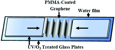
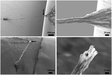
The graphene fibers were fabricated by physically folding a single sheet of single-layer CVD graphene into a 1D-fiber shape in an accordion-like pattern, Fig. 1. Additional details of CVD graphene synthesis and characterization is provided in the ESI† (Fig. S1 and S2). While folding, CVD graphene was supported by a thin layer of polymethyl methacrylate (PMMA). This polymer coating was decomposed and removed by annealing the fiber at 420 °C after folding, above the thermal decomposition temperature of PMMA (390 °C), Fig. S3 (ESI†). The accordion-like folding pattern (Fig. 1) was selected for maximizing the surface area of exposed PMMA in order to prevent the decomposition products from being trapped within the fiber structure upon heat treatment. As an example of a poor folding pattern, thermally annealed rolled/scrolled fiber structures are shown in Fig. S5 (ESI†)—where the decomposed PMMA becomes trapped between the rolled graphene layers, resulting in bubbled structures on the surface and a hollow fiber. Since only one single CVD graphene sheet was used for each fiber, the dimensions of the flat graphene sheet were used to calculate the ideal cross-sectional area of the graphene in the fiber (Agraphene) by using the width (prior to folding) of the graphene sheet and the thickness of graphene (0.335 nm). For a 1 cm-wide CVD graphene sheet, the ideal cross-sectional area is 3.35 μm2.Scanning electron microscopy (SEM) images of annealed graphene fibers, Fig. 2, folded in an accordion-like pattern, reveal that this folding pattern produces a cohesive straight fiber that does not exhibit any bubbled or hollow structures like that in the annealed rolled fibers, Fig. S5 (ESI†). This is due to the accordion pattern allowing for decomposition/removal of PMMA without being trapped between graphene layers. After annealing, the typical nominal diameter of the fibers was between 10 and 100 μm. The presence of both lateral and axial folds is observed in the final annealed fiber. The initial length of the graphene fibers (Lfiber), after fabrication, was measured using a digital microscope and were typically within 0.1–2.0 cm.
These graphene fibers were mounted onto a custom uniaxial testing setup (Fig. S4, ESI†), where both the force, F, and displacement, ΔL, along the fiber were measured. The fibers were loaded in tension until breaking, and the resulting broken fiber segments were re-mounted and testing was repeated. Ideal stress was calculated as F/Agraphene, where Agraphene is the cross-sectional area of the graphene fiber calculated using the initial pre-folded CVD graphene sheet width and atomic thickness—similar to the method used for the previously reported measurements on CNTs. Strain was calculated by ΔL/L0, where L0 was the initial fiber length, as described in the ESI.† The modulus of the fibers, Kfiber, was determined from the slope of the linear portion of the stress–strain curve, and the tensile breaking strength was calculated from the stress at the time of breaking.
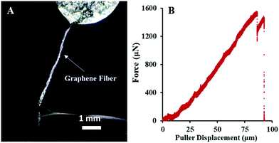
We observed two distinct types of fracture mechanisms in the graphene fibers upon tensile loading. The first type, herein referred to as brittle, is associated with rapid breaking of the fiber after fracture initiation. In this case, the corresponding force–distance curve shows an instantaneous vertical drop in the force from breaking strength to baseline. The second type, herein referred to as ductile, involves a gradual propagation of the fracture across the width of the fiber, the initiation of which correlates to a plateauing of the measured force in the force–distance curve.
Our measurements revealed that brittle fractures correlated with a lower breaking strength and were associated with longer fibers. An example of such a fracture behavior is shown in Fig. 3 and Video S1 (ESI†), for a fiber that is ca. 3 mm in length and an ideal breaking strength of 0.475 GPa.
Ductile fracturing was only observed on smaller fragments produced after multiple cycles of tensile measurements. This ductile fracture mechanism resulted in a higher tensile strength in comparison to the brittle-fracture samples (Fig. 4 and Video S2, ESI†). Top of Fig. 4 (frames 1–3) depicts three video frames during the tensile testing of a ductile fiber. Frame 1 was taken after the macroscopic bends along the axis were removed by the axial movement of the tensile testing setup, forming a more linear fiber. Changes in the diameter and length from this point are a combination of further unbending and elastic or plastic deformation inside the fiber, which was measured optically. Frame 2 was captured right before the graphene fiber fractured, whereby the ideal breaking strength was calculated to be 2.67 GPa. Frame 3 shows the fiber after breaking, where the sum of the lengths of the broken pieces is larger than the Lfiber value of frame 1, indicating some plastic deformation which occurred during testing. These results show a total strain to failure for this wire of 11.4%, where both plastic and elastic deformation play a role. The stress–strain curve for this test is shown in Fig. 4, with a measured modulus Kfiber value of 61.85 GPa ± 2.26 GPa.
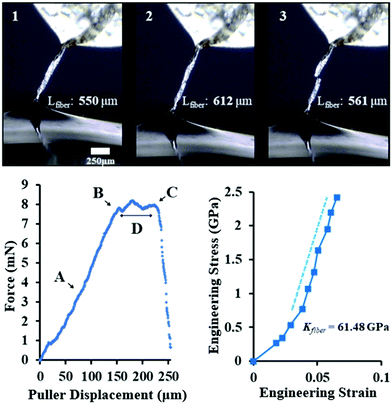 | ||
| Fig. 4 Uniaxial tensile testing of graphene fiber exhibiting ductile fracture. (Agraphene = 1.84 μm2, rp = 0.50 μm s−1) Top: Three frames (1–3) of a graphene fiber uniaxial tensile test. (frame 1) Graphene fiber (Lfiber = 550 μm) after straightening the macroscopic bends in the fiber; (frame 2) fracture initiation (Lfiber = 612 μm), (position B); (frame 3) post-fracture (Lfiber = 561 μm). Bottom: Force–Distance plot (Left) of graphene fiber depicted in Top. (A and B) Represents region of the stress–strain curve (right plot) used to calculate the fiber modulus Kfiber = 61.48 GPa ± 2.26 GPa. Point B refers to the fracture initiation of the graphene fiber. The maximum force at point (C) can be used to calculate breaking strength. The graphene fiber fractured in an unzipping pattern (see Video S2, ESI†), which is also evident by the gradual (rather than immediate) reduction to zero force. Point (D) refers to the plateau region of force during unzipping of fiber. | ||
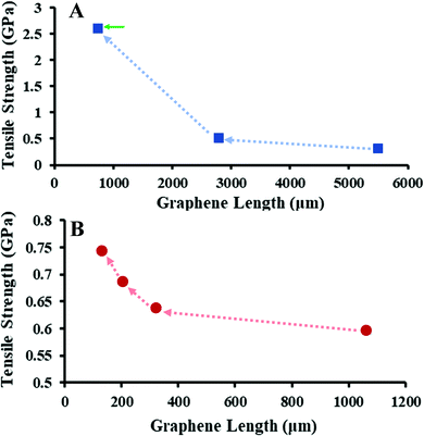
The tensile response of the fiber fragments is affected by the plastic deformation of previous tensile tests. Fig. 5 shows the plot of the tensile strength measured on two fibers and their resulting fragments. In both cases, we observed a gradual increase of breaking strength for all sequential tensile measurements, where the longest fiber had the lowest breaking strength, and the shortest fragment had the largest breaking strength. We conjecture that this behavior is partially explained by the fibers fracturing and breaking at the location of their most critical flaw(s) during uniaxial testing; this results in fiber fragments which must therefore only have flaw(s) of equal or lesser nature. The final measurement of the fiber in Fig. 5A, indicated by a green arrow, is a fragment which exhibited ductile fracturing behavior. We conjecture that straightening and alignment of folds during repetitive uniaxial tests may also be a cause for the mechanical improvements we observe. Comparing the surface morphology of pre-(Fig. 2A and B) and post-(Fig. 2C, D and Fig. S6, ESI†) tensile testing reveals that during the uniaxial tensile tension there is a reduction in folds/wrinkles orthogonal to the pulling axis, as well as alignment of folds/wrinkles parallel to the pulling axis. Analogous observations have been reported for G/GO fibers during stress relaxation upon uniaxial tension.15,34 Similar enhancements have been observed for GO films during cyclic tensile tests.33
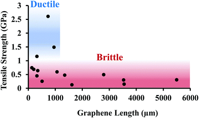
Fig. 6 shows tensile strength measurements of fibers as a function of the fiber length. There is a large variation in the average breaking strength for brittle fractures (0.45 GPa ± 0.20 GPa). The fibers exhibiting ductile behavior were all smaller fragments of a parent fiber. However, this behavior cannot simply be described using the conventional weakest-link statistics because there was no generalized correlation between length of the fiber and fracture strength (as is predicted from a statistical distribution of flaw sizes). We note that the existence of two types of graphene fracture behavior has been previously reported.35
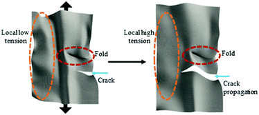
The separation of graphene fiber fragments into brittle and ductile regimes is presumed to be a function of several factors, which include the number of limiting critical defects and the structure and quality of the graphene fiber in which the crack propagates. Crack propagation likely occurs through an unzipping mechanism, which has been previously reported for CVD graphene.35 Hwangbo et al. also reported that this unzipping fracture mechanism can be heavily influenced by the surrounding environment.35 We conjecture that fracture in the graphene is occurring locally along the most energetically favourable paths, such as grain boundaries and defects. Control of these grain boundaries and defects may lead to further enhancement of mechanical properties.36 We believe that the force plateau is achieved through a global load-rebalancing mechanism. Although the graphene sheet is highly folded along the axial direction, other folds are in random orientations, so different regions of the sheet will experience different degrees of tension. These folds could be present at the fracturing location and oriented in a way that applied tension could not be distributed; this partial loading would reduce the effective Agraphene and calculated ideal tensile strength. As a higher-tension region fails, other portions of the fiber will take up the load. As an example, Fig. 7 shows a schematic of adjacent regions of the sheet with high and low stiffness due to different degrees of folding. When the crack propagates into a localized region that is under lower stress, the crack will be arrested, preventing catastrophic failure and transferring the load to other regions. The tensile strength and modulus of our graphene fiber system could be simulated theoretically on a size scale under computational efficiency limits, similarly to previously reported fracture mechanics modelled for graphene.21,37
We note that for the fibers exhibiting ductile fracture behavior, the force remains relatively constant as the graphene fracture propagates. While the graphene unzips, the true cross-sectional area of the graphene in the fiber is continuously reduced. Therefore, the measured breaking strength values are still an underestimation of the ideal strength of the graphene fibers.
Conclusions
We developed a fabrication technique for single sheets of CVD graphene into macroscale graphene fibers and measured their mechanical properties. Our results highlight the potential of using CVD graphene to fabricate high performance macroscopic structures. The effective tensile strength of our graphene fibers increased with decreasing length of the fiber for repeated tests on a single fiber. Graphene fibers exhibited either ductile or brittle fracture behavior. We believe that the lasting plastic deformation built upon sequential tensile testing plays a key role in these properties. The results suggest that optimizing interlayer coupling is necessary to control mechanical efficiency—between increasing interlayer coupling to improve load transfer and balancing and limiting it to prevent large variations of tension within a sheet that led to premature fracture. The average ideal breaking strength for fibers exhibiting ductile behavior was 1.75 GPa ± 0.62 GPa, with the largest breaking strength of 2.67 GPa.Conflicts of interest
There are no conflicts to declare.Acknowledgements
H. L. acknowledges NSF (CBET-2028826) for partial support of this work.References
- K. S. Novoselov, A. K. Geim, S. V. Morozov, D. Jiang, Y. Zhang, S. V. Dubonos, I. V. Grigorieva and A. A. Firsov, Electric field effect in atomically thin carbon films, Science, 2004, 306(5696), 666–669 CrossRef CAS PubMed.
- Q. Zhao, M. B. Nardelli and J. Bernholc, Ultimate strength of carbon nanotubes: a theoretical study, Phys. Rev. B: Condens. Matter Mater. Phys., 2002, 65(14), 144105 CrossRef.
- P. M. Ajayan and J. M. Tour, Nanotube composites, Nature, 2007, 447, 1066 CrossRef CAS PubMed.
- G. Cao, Atomistic Studies of Mechanical Properties of Graphene, Polymers, 2014, 6(9), 2404–2432 CrossRef.
- K. D. Bakoglidis, J. Palisaitis, R. B. dos Santos, R. Rivelino, P. O. Å. Persson, G. K. Gueorguiev and L. Hultman, Self-Healing in Carbon Nitride Evidenced As Material Inflation and Superlubric Behavior, ACS Appl. Mater. Interfaces, 2018, 10(19), 16238–16243 CrossRef CAS PubMed.
- H. Högberg, C.-C. Lai, E. Broitman, I. G. Ivanov, C. Goyenola, L.-Å. Näslund, S. Schmidt, L. Hultman, J. Rosen and G. K. Gueorguiev, Reactive sputtering of CSx thin solid films using CS2 as precursor, Vacuum, 2020, 182, 109775 CrossRef.
- D. Qian, G. J. Wagner, W. K. Liu, M.-F. Yu and R. S. Ruoff, Mechanics of carbon nanotubes, Appl. Mech. Rev., 2002, 55(6), 495–533 CrossRef.
- M.-F. Yu, O. Lourie, M. J. Dyer, K. Moloni, T. F. Kelly and R. S. Ruoff, Strength and Breaking Mechanism of Multiwalled Carbon Nanotubes Under Tensile Load, Science, 2000, 287(5453), 637–640 CrossRef CAS PubMed.
- Y. Zhang and C. Pan, Measurements of mechanical properties and number of layers of graphene from nano-indentation, Diamond Relat. Mater., 2012, 24, 1–5 CrossRef CAS.
- C. Lee, X. Wei, J. W. Kysar and J. Hone, Measurement of the Elastic Properties and Intrinsic Strength of Monolayer Graphene, Science, 2008, 321(5887), 385–388 CrossRef CAS PubMed.
- D. Akinwande, C. J. Brennan, J. S. Bunch, P. Egberts, J. R. Felts, H. Gao, R. Huang, J.-S. Kim, T. Li, Y. Li, K. M. Liechti, N. Lu, H. S. Park, E. J. Reed, P. Wang, B. I. Yakobson, T. Zhang, Y.-W. Zhang, Y. Zhou and Y. Zhu, A review on mechanics and mechanical properties of 2D materials—Graphene and beyond, Extreme Mech. Lett., 2017, 13, 42–77 CrossRef.
- S. Zamani, J. S. Won, M. Salim, M. AlAmer, C.-W. Chang, P. Kumar, K. Amponsah, A. R. Lim and Y. L. Joo, Ultralight graphene/graphite hybrid fibers via entirely water-based processes and their application to density-controlled, high performance composites, Carbon, 2021, 173, 880–890 CrossRef CAS.
- Z. Xu, Y. Liu, X. Zhao, L. Peng, H. Sun, Y. Xu, X. Ren, C. Jin, P. Xu, M. Wang and C. Gao, Ultrastiff and Strong Graphene Fibers via Full-Scale Synergetic Defect Engineering, Adv. Mater., 2016, 28(30), 6449–6456 CrossRef CAS PubMed.
- B. Fang, D. Chang, Z. Xu and C. Gao, A Review on Graphene Fibers: expectations, Advances, and Prospects, Adv. Mater., 2020, 32(5), 1902664 CrossRef CAS PubMed.
- P. Li, Y. Liu, S. Shi, Z. Xu, W. Ma, Z. Wang, S. Liu and C. Gao, Highly Crystalline Graphene Fibers with Superior Strength and Conductivities by Plasticization Spinning, Adv. Funct. Mater., 2020, 30(52), 2006584 CrossRef CAS.
- Z. W. Pan, S. S. Xie, L. Lu, B. H. Chang, L. F. Sun, W. Y. Zhou, G. Wang and D. L. Zhang, Tensile tests of ropes of very long aligned multiwall carbon nanotubes, Appl. Phys. Lett., 1999, 74(21), 3152–3154 CrossRef CAS.
- P. T. Araujo, M. Terrones and M. S. Dresselhaus, Defects and impurities in graphene-like materials, Mater. Today, 2012, 15(3), 98–109 CrossRef CAS.
- S. Deng and V. Berry, Wrinkled, rippled and crumpled graphene: an overview of formation mechanism, electronic properties, and applications, Mater. Today, 2016, 19(4), 197–212 CrossRef CAS.
- Y. Wang and Z. Liu, Spontaneous rolling-up and assembly of graphene designed by using defects, Nanoscale, 2018, 10(14), 6487–6495 RSC.
- A. Zandiatashbar, G.-H. Lee, S. J. An, S. Lee, N. Mathew, M. Terrones, T. Hayashi, C. R. Picu, J. Hone and N. Koratkar, Effect of defects on the intrinsic strength and stiffness of graphene, Nat. Commun., 2014, 5(1), 3186 CrossRef PubMed.
- B. Javvaji, P. R. Budarapu, V. K. Sutrakar, D. R. Mahapatra, M. Paggi, G. Zi and T. Rabczuk, Mechanical properties of graphene: molecular dynamics simulations correlated to continuum based scaling laws, Comput. Mater. Sci., 2016, 125, 319–327 CrossRef CAS.
- A. A. Griffith and G. I. Taylor VI, The phenomena of rupture and flow in solids, Philos. Trans. R. Soc., A, 1921, 221(582–593), 163–198 Search PubMed.
- E. W. Wong, P. E. Sheehan and C. M. Lieber, Nanobeam Mechanics: elasticity, Strength, and Toughness of Nanorods and Nanotubes, Science, 1997, 277(5334), 1971–1975 CrossRef CAS.
- M.-F. Yu, B. S. Files, S. Arepalli and R. S. Ruoff, Tensile Loading of Ropes of Single Wall Carbon Nanotubes and their Mechanical Properties, Phys. Rev. Lett., 2000, 84(24), 5552–5555 CrossRef CAS PubMed.
- Y. Li, K. Wang, J. Wei, Z. Gu, Z. Wang, J. Luo and D. Wu, Tensile properties of long aligned double-walled carbon nanotube strands, Carbon, 2005, 43(1), 31–35 CrossRef CAS.
- H. W. Zhu, C. L. Xu, D. H. Wu, B. Q. Wei, R. Vajtai and P. M. Ajayan, Direct Synthesis of Long Single-Walled Carbon Nanotube Strands, Science, 2002, 296(5569), 884–886 CrossRef CAS PubMed.
- N. Mittal, F. Ansari, V. K. Gowda, C. Brouzet, P. Chen, P. T. Larsson, S. V. Roth, F. Lundell, L. Wågberg, N. A. Kotov and L. D. Söderberg, Multiscale Control of Nanocellulose Assembly: transferring Remarkable Nanoscale Fibril Mechanics to Macroscale Fibers, ACS Nano, 2018, 12(7), 6378–6388 CrossRef CAS PubMed.
- Z. Xu, Z. Liu, H. Sun and C. Gao, Highly Electrically Conductive Ag-Doped Graphene Fibers as Stretchable Conductors, Adv. Mater., 2013, 25(23), 3249–3253 CrossRef CAS PubMed.
- S. H. Aboutalebi, R. Jalili, D. Esrafilzadeh, M. Salari, Z. Gholamvand, S. Aminorroaya Yamini, K. Konstantinov, R. L. Shepherd, J. Chen, S. E. Moulton, P. C. Innis, A. I. Minett, J. M. Razal and G. G. Wallace, High-Performance Multifunctional Graphene Yarns: toward Wearable All-Carbon Energy Storage Textiles, ACS Nano, 2014, 8(3), 2456–2466 CrossRef CAS PubMed.
- S. Liu, Y. Wang, X. Ming, Z. Xu, Y. Liu and C. Gao, High-Speed Blow Spinning of Neat Graphene Fibrous Materials, Nano Lett., 2021, 21(12), 5116–5125 CrossRef CAS PubMed.
- B. Wang, M. Huang, N. Y. Kim, B. V. Cunning, Y. Huang, D. Qu, X. Chen, S. Jin, M. Biswal, X. Zhang, S. H. Lee, H. Lim, W. J. Yoo, Z. Lee and R. S. Ruoff, Controlled Folding of Single Crystal Graphene, Nano Lett., 2017, 17(3), 1467–1473 CrossRef CAS PubMed.
- I. Vlassiouk, G. Polizos, R. Cooper, I. Ivanov, J. K. Keum, F. Paulauskas, P. Datskos and S. Smirnov, Strong and Electrically Conductive Graphene-Based Composite Fibers and Laminates, ACS Appl. Mater. Interfaces, 2015, 7(20), 10702–10709 CrossRef CAS PubMed.
- Z. Dai, Y. Wang, L. Liu, X. Liu, P. Tan, Z. Xu, J. Kuang, Q. Liu, J. Lou and Z. Zhang, Hierarchical Graphene-Based Films with Dynamic Self-Stiffening for Biomimetic Artificial Muscle, Adv. Funct. Mater., 2016, 26(38), 7003–7010 CrossRef CAS.
- M. Yang, Z. Wang, P. Li, Y. Liu, J. Lin, B. Wang, X. Ming, W. Gao, Z. Xu and C. Gao, Stress relaxation behaviors of graphene fibers, Carbon, 2021, 182, 384–392 CrossRef CAS.
- Y. Hwangbo, C.-K. Lee, S.-M. Kim, J.-H. Kim, K.-S. Kim, B. Jang, H.-J. Lee, S.-K. Lee, S.-S. Kim, J.-H. Ahn and S.-M. Lee, Fracture Characteristics of Monolayer CVD-Graphene, Sci. Rep., 2014, 4, 4439 CrossRef PubMed.
- J. Xu, G. Yuan, Q. Zhu, J. Wang, S. Tang and L. Gao, Enhancing the Strength of Graphene by a Denser Grain Boundary, ACS Nano, 2018, 12(5), 4529–4535 CrossRef CAS PubMed.
- Z. Zhang, X. Wang and J. D. Lee, An atomistic methodology of energy release rate for graphene at nanoscale, J. Appl. Phys., 2014, 115(11), 114314 CrossRef.
Footnotes |
| † Electronic supplementary information (ESI) available: Additional experimental details, Fig. S1–S6. Uniaxial tensile test Videos S1 and S2. See DOI: 10.1039/d1cp03238k |
| ‡ These authors contributed equally to this work. |
| This journal is © the Owner Societies 2021 |

