 Open Access Article
Synthesis of a hierarchical carbon fiber@cobalt ferrite@manganese dioxide composite and its application as a microwave absorber
Ailing Fenga,
Tianqi Houb,
Zirui Jia*b and
Guanglei Wu *bc
*bc
aInstitute of Physics & Optoelectronics Technology, Baoji University of Arts and Sciences, Baoji 721016, P. R. China
bInstitute of Materials for Energy and Environment, State Key Laboratory of Bio-fibers and Eco-textiles, College of Materials Science and Engineering, Qingdao University, Qingdao 266071, P. R. China. E-mail: jiazirui@mail.nwpu.edu.cn; wuguanglei@mail.xjtu.edu.cn; wuguanglei@qdu.edu.cn; Fax: +86 532 85951496; Tel: +86 532 85951496
cKey Laboratory of Engineering Dielectrics and Its Application, Ministry of Education, Harbin University of Science and Technology, Harbin 150080, PR China
First published on 11th March 2020
Abstract
In this study, a novel hierarchical carbon fiber@cobalt ferrite@manganese dioxide (CF@CoFe2O4@MnO2) composite was facilely prepared via a sol–gel method and hydrothermal reaction. The morphology, structure, chemical and element composition, crystal form, elemental binding energy, magnetic behavior and microwave absorbing performance of the composite were carefully investigated. According to its hysteresis loops, the composite exhibits a typical soft magnetic behavior, with a Ms value of 30.2 emu g−1. Besides, the as-synthesized CF@CoFe2O4@MnO2 composite exhibits superior microwave absorption performance mainly due to reasonable electromagnetic matching, and its minimum reflection loss value can reach −34 dB with a sample thickness of just 1.5 mm. The composite can be regarded as an ideal microwave absorber.
1. Introduction
In recent years, the universal applications of computer technology, electromagnetic medicine, broadcasting, and communication have made microwaves part of human beings' daily lives. Thus, the harm caused by microwaves to humans and their interference with related equipment is receiving increasing attention from all over the world.1–6 Simultaneously, in order to achieve microwave protection, research on microwave absorbing materials has also been rapidly growing. According to the dielectric loss and magnetic loss mechanisms of the microwave, an ideal microwave absorber ought to possess both selective dielectric properties and magnetic properties.7–10 Therefore, the combination of dielectric materials (such as carbon-based materials, conductive polymers, and transition metal oxides) and magnetic materials (metal iron, cobalt, nickel and their compounds) by chemical reactions has been a classic research method for obtaining superior microwave absorbing composites.11–17As a typical soft magnetic material, cobalt ferrite has been widely applied in the preparation of efficient microwave absorption composites. Lv et al.18 developed a novel coin-like core/shell α-Fe2O3@CoFe2O4 composite, which showed excellent EM wave absorbing performance, with a minimum reflection loss value of −41 dB. Besides, RGO/CoFe2O4,19 CNT/CoFe2O4 (ref. 20) and PANI/CoFe2O4 (ref. 21) also exhibit superior microwave absorption performance due to the fair electromagnetic matching.
In view of its strong dielectric properties, manganese dioxide has become an interesting research material when regarded as a microwave absorber. Among others, MnO2 possesses many advantages such as strong designability, simple synthesis method, good stability, and low price. Recently, an ideal microwave absorber comprising a hierarchical Fe3O4@carbon@MnO2 hybrid has been reported by Chen et al.22 The hybrid showed an excellent microwave absorption capacity based on the improvement of dielectric properties by MnO2 with a minimum reflection loss value of −35 dB when the sample thickness is 2.7 mm. Besides, numerous other superior microwave absorbers related to MnO2 such as PANI/MnO2/CF,23 NiFe2O4/MnO2,24 carbonyl iron/MnO2 (ref. 25) were also reported. Thus, it is significant to develop a microwave absorber by using MnO2.26–28
In this study, a novel CF@CoFe2O4@MnO2 composite was facilely prepared. First, a typical sol–gel reaction was adopted to prepare the CF@CoFe2O4 composite. Then, the as-synthesized CF@CoFe2O4 composite was further coated with MnO2 via a hydrothermal reaction to obtain the CF@CoFe2O4@MnO2 composite. The morphology, structure, chemical and element composition, crystal form, elemental binding energy, magnetic behavior, and microwave absorbing performances of the composite were carefully investigated. According to its hysteresis loops, the composite exhibited a typical soft magnetic behavior, with a Ms value of 30.2 emu g−1. Besides, the as-synthesized CF@CoFe2O4@MnO2 composite possesses a superior microwave absorption performance mainly due to reasonable electromagnetic matching, and its minimum reflection loss value can reach −34 dB with a sample thickness of just 1.5 mm. The composite can be regarded as an ideal microwave absorber.
2. Experimental
2.1 Sol–gel method for the synthesis the of CF@CoFe2O4 composite
The CF@CoFe2O4 composite was facilely prepared by a sol–gel method. 2.7 g of FeCl3·6H2O, 1.2 g of CoCl2·6H2O and 0.5 g of CF were uniformly mixed with a moderate amount of C6H8O7. After grinding the material into powder, the mixture was transferred into a flask maintained at 90 °C in a water bath and then 0.5 g ethylene was slowly added to the flask. Then, the pH of the reaction was adjusted to 8–9 by ammonia, after agitating for more than 180 min, the mixture became uniform and the gel was formed. Finally, the gel was calcined at 750 °C for 360 min under an N2 atmosphere to obtain the CF@CoFe2O4 composite.29–312.2 Preparation of the CF@CoFe2O4@MnO2 composite
The CF@CoFe2O4@MnO2 composite was facilely prepared via a hydrothermal reaction. 200 mg of the as-synthesized CF@CoFe2O4@MnO2 composite was homogeneously distributed in 75 mL deionized water by high speed agitation for 1 h. Then, 1.5 mL hydrochloric acid and 1.0 g potassium permanganate were added successively.After another 10 min of high-speed agitation, the liquid mixture was transferred into a 100 mL Teflon-lined stainless-steel autoclave and reacted at 150 °C for 120 min. After naturally cooling it to room temperature, the as-prepared CF@CoFe2O4@MnO2 composite was separated via centrifugation at 10![[thin space (1/6-em)]](https://www.rsc.org/images/entities/char_2009.gif) 000 rpm, successively washed with absolute ethanol for about 7–8 times, and put into a 100 °C blast drying oven for 12 h.32–35
000 rpm, successively washed with absolute ethanol for about 7–8 times, and put into a 100 °C blast drying oven for 12 h.32–35
2.3 Characterization
The specimen morphology, structure, chemical and element compositions were determined via a scanning electron microscope (FESEM, Quanta600FEG) equipped with an energy dispersive X-ray (EDX) spectrometer. Besides, X-ray diffraction (XRD, ESCALAB 250) in the 2 theta range of 10° < 2θ < 80° was adopted to measure the crystal structures of CF, CF@CoFe2O4 and CF@CoFe2O4@MnO2 composites. The binding energy of the CF@CoFe2O4@MnO2 composite was examined via X-ray photoelectron spectroscopy (XPS, Thermal Scientific Kα). The hysteresis loops of CoFe2O4, CF@CoFe2O4 and CF@CoFe2O4@MnO2 composites were characterized using a vibrating sample magnetometer (VSM, Lake Shore7307). For the microwave absorbing performance measurement, the complex permittivity (εr) and permeability (μr) of CF, CF@CoFe2O4 and CF@CoFe2O4@MnO2 composites were investigated using an Agilent HP8720ES vector network analyzer in the frequency range of 2.0–18.0 GHz based on a coaxial method. First, the samples were uniformly distributed in a paraffin phase with the weight ratio of 30%, and then pressed into a cylindrical mold (φin = 3.04 mm, φout = 7.00 mm). Based on the obtained parameters of the samples, the corresponding reflection loss curves were further calculated and their microwave absorption performances could be identified.3. Results and discussions
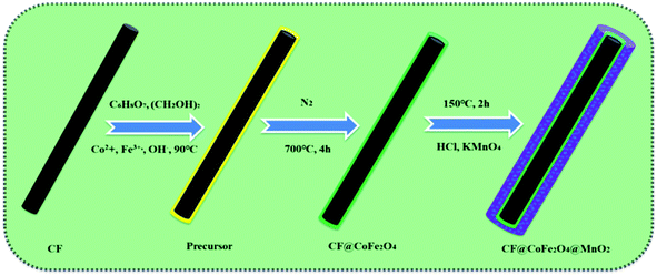
The preparation process of the CF@CoFe2O4@MnO2 composite is briefly illustrated in Fig. 1. First, a typical sol–gel reaction was adopted to synthesize CF@CoFe2O4. Then, in order to make the MnO2 nanocrystals in situ grow along the surface of the CF@CoFe2O4 composite, another hydrothermal reaction was carried out to complete the redox reaction of potassium permanganate and carbon, and the CF@CoiFe2O4 composite was further coated with MnO2 to obtain the CF@CoFe2O4@MnO2 composite. The reactions occurring during the synthesis process are shown as eqn (1) and (2).36–39| Co2+ + 2Fe3+ + 8OH− → Co(OH)2 + 2Fe(OH)3 → CoFe2O4 + 4H2O | (1) |
| 4KMnO4 + 3C + H2O → 4MnO2 + K2CO3 + 2KHCO3 | (2) |
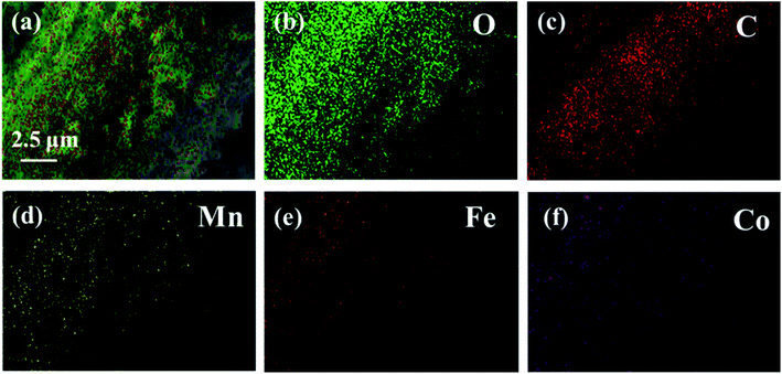
Fig. 2 exhibits the SEM images of CF (a), CF@CoFe2O4 (b), CF@CoFe2O4@MnO2 composites (c) and the EDS spectra of CF@CoFe2O4@MnO2 composite (d). It can be observed from the images that the pre-reaction carbon fiber possesses a smooth surface, and its diameter is about 6–7 μm. After the sol–gel reaction, the surface CF was homogeneously cladded by CoFe2O4 nanoparticles (Fig. 2b), and the thickness of overburden was about 600 nm. Fig. 2c reveals the morphology of the CF@CoFe2O4@MnO2 composite, the CF@CoFe2O4 was uniformly coated with MnO2 after the hydrothermal reaction, and the diameter further increased to around 8.2 nm. The total thickness of the coating layer could be calculated from the size difference (about 750 nm). The CF@CoFe2O4@MnO2 composite's EDX patterns illustrate that the composite was composed of the elements of C, O, Mn, Fe and Co, the composition ratio (wt%) of these elements were 26.13%, 28.06%, 19.17%, 18.82% and 7.82%, respectively. The C element is mainly from the carbon fiber, while the O element can be attributed to the components of CoFe2O4 and MnO2. The above results confirm the successful synthesis of the CF@CoFe2O4@MnO2 composite. Meanwhile, the composite's EDX elemental mapping images (Fig. 3a–f) further identifies the components in the as-synthesized product.40–43
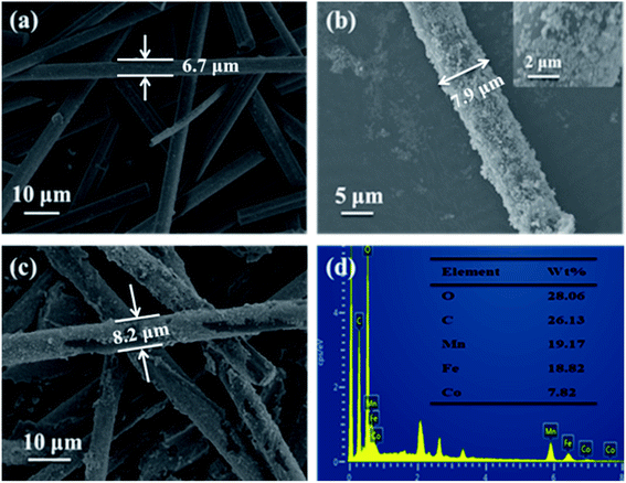 | ||
| Fig. 2 SEM images of CF (a), CF@CoFe2O4 (b), CF@CoFe2O4@MnO2 composites (c) and the EDS spectra of CF@CoFe2O4@MnO2 composite (d). | ||
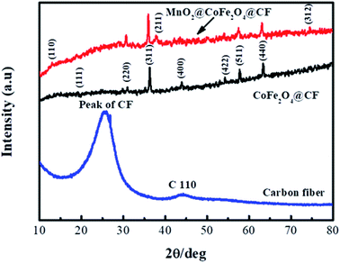
Fig. 4 displays the XRD patterns of CF, CF@CoFe2O4 and CF@CoFe2O4@MnO2 composites, which can be used to investigate the samples' crystal structures. From this figure, the bread peak between 20°–40° represents the crystal plane diffraction peak of CF. After the sol–gel reaction, there are seven diffraction peaks located at 2θ = 18.51°, 30.41°, 35.71°, 43.5°, 53.9°, 57.5° and 63° signifying the (1 1 1), (2 2 0), (3 1 1), (4 0 0), (4 2 2), (5 1 1) and (4 4 0) planes, respectively, of CoFe2O4 (JCPDS card no. 22-1086), in the XRD pattern of CF@CoFe2O4. Compared with the CF@CoFe2O4 sample, the additional two peaks of CF@CoFe2O4@MnO2 composite located at 36.1° and 74.2° belong to MnO2 crystal's (2 1 1) and (3 1 2) plane diffraction peaks, respectively, which can further confirm the successful synthesis of CF@CoFe2O4@MnO2 composite.44–46
Fig. 5 exhibits the XPS spectra of CF@CoFe2O4@MnO2 composite. Fig. 5a is the survey scan spectra, from which the C 1s, Fe 2p, O 1s, Mn 2p, Co 2p binding energy can be observed. In Fig. 5b, the two peaks located at 283.5 eV and 284.6 eV are corresponding to the C–C/C![[double bond, length as m-dash]](https://www.rsc.org/images/entities/char_e001.gif) C and C–O binding energy of C element, respectively. The two peaks located at 711.5 eV and 726.4 eV represent Fe 2p3/2 and Fe 2p1/2 binding energies (Fig. 5c). From Fig. 5c, the 2p1/2 and 2p3/2 belonging to Mn element can obviously be observed. And the Co 2p3/2 and Co 2p1/2 binding energy peaks are located at 782.8 eV and 798.2 eV, respectively, which can be observed in Fig. 5f. The above results jointly verified the elemental composition of the as-synthesized CF@CoFe2O4@MnO2 composite.47–50
C and C–O binding energy of C element, respectively. The two peaks located at 711.5 eV and 726.4 eV represent Fe 2p3/2 and Fe 2p1/2 binding energies (Fig. 5c). From Fig. 5c, the 2p1/2 and 2p3/2 belonging to Mn element can obviously be observed. And the Co 2p3/2 and Co 2p1/2 binding energy peaks are located at 782.8 eV and 798.2 eV, respectively, which can be observed in Fig. 5f. The above results jointly verified the elemental composition of the as-synthesized CF@CoFe2O4@MnO2 composite.47–50
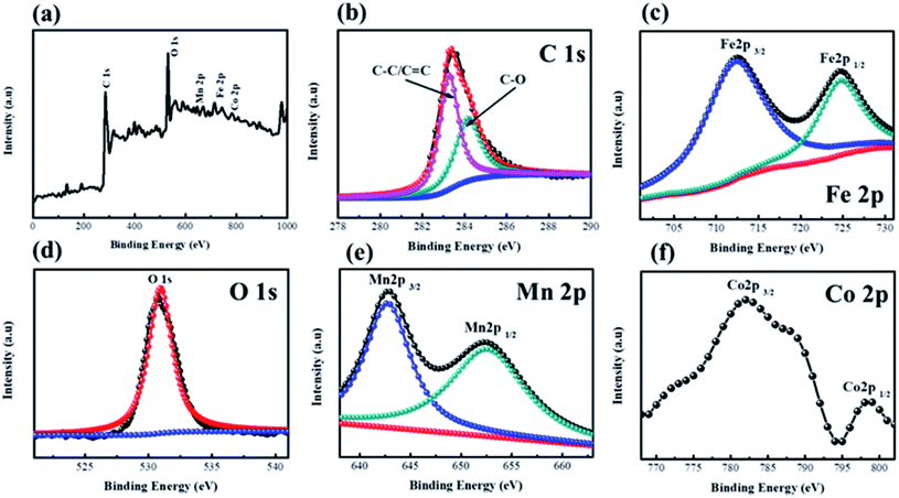 | ||
| Fig. 5 XPS spectra of CF@CoFe2O4@MnO2 composite, a survey scan (a), C 1s (b), Fe 2p (c), O 1s (d), Mn 2p (e), Co 2p (f). | ||
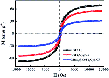
In view of the magnetic loss mechanism of electromagnetic waves, the magnetic behaviors of microwave absorbers have a great effect on their microwave absorbing performance, thus the magnetic hysteresis loops of CoFe2O4, CF@CoFe2O4 and CF@CoFe2O4@MnO2 composites were measured by utilizing VSM and the results are exhibited in Fig. 6. The CoFe2O4, CF@CoFe2O4 and CF@CoFe2O4@MnO2 composites all displayed a typical soft magnetic behavior, which is very beneficial for the absorption of microwaves. The magnetic saturation values of CoFe2O4, CF@CoFe2O4 and CF@CoFe2O4@MnO2 composites were 65.5 emu g−1, 54.8 emu g−1 and 30.2 emu g−1, respectively. The reduction in their magnetic saturation can mainly be attributed to the decrease of the mass ratio of the unique magnetic material CoFe2O4 among these samples.
Normally, when the microwave is incident upon the surface of the sample, it would be reflected or transmitted, meanwhile, the contained microwave energy would be absorbed by magnetic loss and dielectric loss or transformed into heat energy and scattered in the air. In view of the loss mechanism of the microwave, the absorption mode of the microwave can mainly be divided into magnetic loss and dielectric loss, which can be calculated by utilizing its permeability μ′, μ′′ and permittivity ε′, ε′′, respectively. The parameter's real part μ′ and ε′ represent the storage capability of a material, while the imaginary part μ′′ and ε′′ on behalf of the dissipation capability of magnetic energy and electric energy, respectively. Based on μ′, μ′′, ε′ and ε′′, the corresponding reflection loss patterns of the measured samples can be calculated by using eqn (3)–(6).51–57
 | (3) |
| Z0 = (μ0/ε0)1/2 | (4) |
 | (5) |
 | (6) |
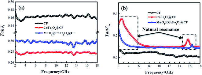
In these formulas, Zin represents normalized input impedance of the absorbing material, Z0 on behalf of the impedance of free space, parameter d stands for the thickness of absorber, parameter c means the light velocity in the vacuum and another parameter f signifies the frequency of the input microwave. Thus, the measured sample's thickness possesses a great effect on its microwave absorption performance. In addition, the absorbers' microwave absorption performances were mainly codetermined by their magnetic property and dielectric property. The electromagnetic parameters of CF, CF@CoFe2O4 and CF@CoFe2O4@MnO2 composites are exhibited in Fig. 7, and the corresponding dielectric loss (tan![[thin space (1/6-em)]](https://www.rsc.org/images/entities/char_2009.gif) δe = ε′′/ε′) and magnetic loss (tan
δe = ε′′/ε′) and magnetic loss (tan![[thin space (1/6-em)]](https://www.rsc.org/images/entities/char_2009.gif) δm = μ′′/μ′) were also calculated and shown in Fig. 8. By comparing the three samples' electromagnetic parameters, as a conductive material, the CF sample possesses high dielectric parameter value (real part ∼ 16 and imaginary part ∼ 7). However, as a nonmagnetic material, the magnetic parameter values of CF are the lowest among these samples (real part ∼ 1 and imaginary part ∼ 0), which is unfavorable to the magnetic loss for electromagnetic waves. After the sol–gel reaction, the dielectric parameter values and tan
δm = μ′′/μ′) were also calculated and shown in Fig. 8. By comparing the three samples' electromagnetic parameters, as a conductive material, the CF sample possesses high dielectric parameter value (real part ∼ 16 and imaginary part ∼ 7). However, as a nonmagnetic material, the magnetic parameter values of CF are the lowest among these samples (real part ∼ 1 and imaginary part ∼ 0), which is unfavorable to the magnetic loss for electromagnetic waves. After the sol–gel reaction, the dielectric parameter values and tan![[thin space (1/6-em)]](https://www.rsc.org/images/entities/char_2009.gif) δe of CF@CoFe2O4 decreased while its magnetic parameters (real part, imaginary part and magnetic loss) were all increased, which can mainly be attributed to the introduction of magnetic material CoFe2O4. Compared with CF@CoFe2O4, the CF@CoFe2O4@MnO2 composite's magnetic loss was reduced, while the dielectric loss was improved (real part ∼ 10.8 and imaginary part ∼ 3.2), which can result in a more reasonable electromagnetic matching, further enhancing the sample's microwave absorbing performance. Besides, the CF@CoFe2O4 sample the CF@CoFe2O4@MnO2 composite sample exhibited resonance phenomenon, which is considered to be associated with local confinement, natural resonance and exchange resonance loss.58–62
δe of CF@CoFe2O4 decreased while its magnetic parameters (real part, imaginary part and magnetic loss) were all increased, which can mainly be attributed to the introduction of magnetic material CoFe2O4. Compared with CF@CoFe2O4, the CF@CoFe2O4@MnO2 composite's magnetic loss was reduced, while the dielectric loss was improved (real part ∼ 10.8 and imaginary part ∼ 3.2), which can result in a more reasonable electromagnetic matching, further enhancing the sample's microwave absorbing performance. Besides, the CF@CoFe2O4 sample the CF@CoFe2O4@MnO2 composite sample exhibited resonance phenomenon, which is considered to be associated with local confinement, natural resonance and exchange resonance loss.58–62
According to the measured ε′, ε′′, μ′, μ′′, the reflection loss patterns at different thicknesses ranging from 2–18 GHz of CF (a), CF@CoFe2O4 (b) and CF@CoFe2O4@MnO2 composite (c) samples were calculated and the results are exhibited in Fig. 8. As shown in Fig. 8a, as a nonmagnetic material, the EM wave absorbing capacity of a pure carbon fiber is poor and its minimum reflection loss (RL min) value is −15 dB with a specimen thickness of 1.6 mm. However, when combined with magnetic material CoFe2O4 via the sol–gel method, the CF@CoFe2O4, its microwave absorbing performance was enhanced, and the minimum reflection loss value is less −20 dB, which can mainly be attributed to the enhancement of magnetic loss. When further combined with MnO2, the CF@CoFe2O4@MnO2 composite possesses a strong microwave absorbing capacity, which can reach up to −41 dB, far higher than the CF and CF@CoFe2O4 samples. The effective absorption bandwidth (EAB) of CF@CoFe2O4@MnO2 composite is shown in Fig. 9d, it can obviously be observed that when the sample thickness is just 1.5 mm, its minimum reflection loss value and EAB value can reach −34 dB and 5 GHz, respectively, indicating that the composite can achieve high absorption efficiency and wide EAB under a small thickness, which is very beneficial for further applications.63–65
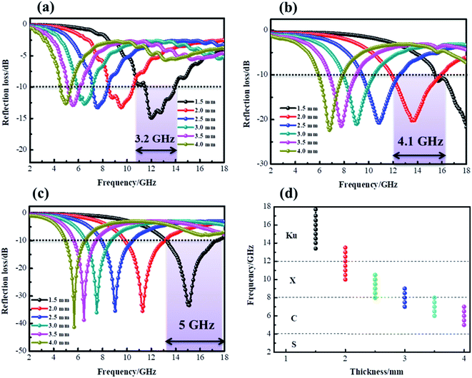 | ||
| Fig. 9 Reflection loss curves of CF (a), CF@CoFe2O4 (b) and CF@CoFe2O4@MnO2 composites (c) at a different thickness, the effective absorption band width of CF@CoFe2O4@MnO2 composite (d). | ||
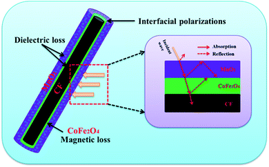
The above results illustrate that the as-synthesized CF@CoFe2O4@MnO2 composite exhibits superior microwave absorption performance both in absorbing efficiency and EAB width with a low thickness. The mechanism sketch illustration of microwave absorption for the CF@CoFe2O4@MnO2 composite is shown in Fig. 10. First, the dielectric material CF, MnO2 and magnetic material CoFe2O4 can achieve fair electromagnetic matching. Second, the multiple interfaces that emerged from its layer-by-layer cladding structure can increase absorption times of EM wave. Third, the interfacial polarizations and interface relaxation between MnO2 and NiFe2O4 can further enhance its microwave capacity. These factors codetermined the excellent microwave absorbing properties of the CF@CoFe2O4@MnO2 composite.66–71 When compared with other reported homologous microwave absorber including Fe3O4@C@MnO2,28 CNT/CoFe2O4,46 PANI/MnO2/CF,61 NiFe2O4@MnO2,33 carbonyl iron/MnO2,58 PANI@Ni@CF42 and α-Fe2O3@CoFe2O4 (ref. 59) (Table 1), the as-synthesized CF@CoFe2O4@MnO2 composite showed excellent EM wave absorption performance.
| Sample | Frequency range (GHz) | Weight percent of filler | Adhesive | Thickness | RL min | EAB width (GHz) | Reference |
|---|---|---|---|---|---|---|---|
| Fe3O4@C@MnO2 | 2–18 | 30% | Paraffin wax | 2.7 mm | −35 dB | 5.0 | 28 |
| CNT/CoFe2O4 | 2–18 | N.A | N.A | 1.4 mm | −18 dB | 7.0 | 46 |
| PANI/MnO2/CF | 8.2–12.4 | 30% | Paraffin wax | 2.5 mm | −22 dB | 3.0 | 61 |
| NiFe2O4@MnO2 | 2–18 | 30% | Paraffin wax | 2.0 mm | −25 dB | 2.7 | 33 |
| Carbonyl iron/MnO2 | 2–18 | 30% | Paraffin wax | 3.5 mm | −39.1 dB | 3.0 | 58 |
| PANI@Ni@CF | 8.2–12.4 | 20% | Paraffin wax | 2.0 mm | −12.4 dB | 1.2 | 42 |
| α-Fe2O3@CoFe2O4 | 2–18 | 30% | Paraffin wax | 2.5 mm | −41 dB | 5.0 | 59 |
| CF@CoFe2O4@MnO2 | 2–18 | 30% | Paraffin wax | 1.5 mm | −34 dB | 5.0 | This work |
4. Conclusion
In summary, a uniform CF@CoFe2O4@MnO2 composite was facilely fabricated via a two-step method, a sol–gel method and a hydrothermal reaction. The morphology, structure, chemical and element composition, crystal form, elemental binding energy, magnetic behavior, and microwave absorbing performances of the composite were carefully investigated. According to its hysteresis loops, the composite exhibited a typical soft magnetic behavior, with an Ms value of 30.2 emu g−1. Besides, the as-synthesized CF@CoFe2O4@MnO2 composite possesses superior microwave absorption performance mainly due to a reasonable electromagnetic matching, and its minimum reflection loss value can reach −34 dB with a sample thickness of just 1.5 mm. The composite can be regarded as an ideal microwave absorber.Conflicts of interest
The authors declare no conflict of interest.Acknowledgements
This work was financially supported by the Natural Science Foundation of Shandong Province (ZR2019YQ24), the Qingchuang Talents Induction Program of Shandong Higher Education Institution (Research and Innovation Team of Structural-Functional Polymer Composites), National Natural Science Foundation of China (51407134, 51801001), China Postdoctoral Science Foundation (2016M590619, 2016M601878), Qingdao Postdoctoral Application Research Project, Key Laboratory of Engineering Dielectrics and Its Application (Harbin University of Science and Technology), Ministry of Education (KFZ1803), Provincial Key Research and Development Program of Shaanxi (2019GY-197), Key Project of Baoji University of Arts and Sciences (ZK2018051), Baoji Science and Technology Project (16RKX1-29) and Baoji Engineering Technology Research Center for Ultrafast Optics and New Materials (2015CXNL-1-3). Feng AL is supported by The Thousand Talents Plan for Young Professionals of Shaanxi Province.References
- H. L. Lv, Z. H. Yang, S. J. H. Ong, C. Wei, H. B. Liao, S. B. Xi, Y. H. Du, G. B. Ji and Z. C. J. Xu, Adv. Funct. Mater., 2019, 29, 1900163 CrossRef.
- H. L. Xu, X. W. Yin, X. L. Li, M. H. Li, S. Liang, L. F. Cheng and L. T. Zhang, ACS Appl. Mater. Interfaces, 2019, 11, 10198–10207 CrossRef CAS PubMed.
- C. Cheng, Z. Chen, Z. Huang, C. Zhang, R. Tusiime, J. Zhou, Z. Sun, Y. Liu, H. Zhang and M. Yu, Composites, Part A, 2020, 129, 105696 CrossRef.
- C. Liang, H. Qiu, P. Song, X. Shi, J. Kong and J. Gu, Sci. Bull., 2020 DOI:10.1016/j.scib.2020.02.009.
- X. Chen, T. Shi, K. Zhong, G. Wu and Y. Lu, Chem. Eng. J., 2020, 379, 122240 CrossRef CAS.
- S. Chen, G. Meng, B. Kong, B. Xiao, Z. Wang, Z. Jing, Y. Gao, G. Wu, H. Wang and Y. Cheng, Chem. Eng. J., 2020, 387, 123662 CrossRef CAS.
- A. Feng, G. Wu, C. Pan and Y. Wang, J. Nanosci. Nanotechnol., 2017, 17, 3786–3791 CrossRef CAS.
- Y. Wang, K. Kou and L. Zhuo, RSC Adv., 2016, 5(72), 58821–58831 RSC.
- B. Zhao, J. Deng, C. Zhao, C. Wang, Y. Chen, M. Hamidinejad, R. Li and C. Park, J. Mater. Chem. C, 2020, 8, 58 RSC.
- C. Liang, P. Song, H. Qiu, Y. Zhang, X. Ma, F. Qi, H. Gu, J. Kong and J. Gu, Nanoscale, 2019, 11, 22590–22598 RSC.
- H. Zhang, Z. Jia, A. Feng, Z. Zhou, C. Zhang, K. Wang and N. Liu, Compos. Commun., 2020 DOI:10.1016/j.coco.2020.02.010.
- P. Song, H. Qiu, L. Wang, X. Liu, Y. Zhang, J. Zhang, J. Kong and J. Gu, Sustainable Mater. Technol., 2020 DOI:10.1016/j.susmat.2020.e00153.
- J. Li, J. Ma, S. Chen, Y. Huang and J. He, Mater. Sci. Eng., C, 2018, 89, 25–32 CrossRef CAS PubMed.
- C. Zhang, K. Zeng, C. Wang, X. Liu, G. Wu, Z. Wang and D. Wang, Ceram. Int., 2020, 46, 6652–6662 CrossRef.
- A. Feng, T. Hou, Z. Jia, Y. Zhang and F. Zhang, Nanomaterials, 2020, 10, 162 CrossRef CAS PubMed.
- Z. Wang, M. Yang, Y. Cheng, J. Liu, B. Xiao, S. Chen, J. Huang and Q. Xie, Composites, Part A, 2019, 118, 302–311 CrossRef CAS.
- G. Wu, Z. Jia, Y. Cheng, H. Zhang, X. Zhou and H. Wu, Appl. Surf. Sci., 2019, 10, 472–478 CrossRef.
- H. Lv, X. Liang, G. Ji, H. Zhang and Y. Du, ACS Appl. Mater. Interfaces, 2015, 7, 9776–9783 CrossRef CAS PubMed.
- Y. Cheng, J. M. Cao, Y. Li, Z. Y. Li, H. Q. Zhao, G. B. Ji and Y. W. Du, ACS Sustainable Chem. Eng., 2018, 6, 1427–1435 CrossRef CAS.
- X. Liang, B. Quan, B. Sun, Z. Man, X. Xu and G. Ji, ACS Sustainable Chem. Eng., 2019, 7, 10477–10483 CrossRef CAS.
- B. Quan, W. Shi, S. J. H. Ong, X. Lu, P. L. Wang, G. Ji and Z. J. Xu, Adv. Funct. Mater., 2019, 29(28), 1901236 CrossRef.
- X. Cui, X. Liang, J. Chen, W. Gu, G. Ji and Y. Du, Carbon, 2020, 156, 49–57 CrossRef CAS.
- S. K. Singh, M. J. Akhtar and K. K. Kar, Composites, Part B, 2019, 167, 135–146 CrossRef CAS.
- P. Liu, Y. Huang and X. Zhang, Powder Technol., 2015, 276, 112–117 CrossRef CAS.
- P. Chamoli, S. K. Singh, M. J. Akhtar, M. K. Das and K. K. Kar, Phys. E, 2018, 103, 25–34 CrossRef CAS.
- Y. Wang, K. Kou, C. Pan and A. Feng, J. Mater. Sci.: Mater. Electron., 2016, 27(8), 8279–8287 CrossRef CAS.
- H. Wu, Z. Zhao and G. Wu, J. Colloid Interface Sci., 2020, 566, 21–32 CrossRef CAS PubMed.
- X. L. Chen, Z. R. Jia, A. L. Feng, B. B. Wang, X. H. Tong, C. H. Zhang and G. L. Wu, J. Colloid Interface Sci., 2019, 553, 465–474 CrossRef CAS PubMed.
- S. K. Singh, H. Prakash, M. J. Akhtar and K. K. Kar, ACS Sustainable Chem. Eng., 2018, 6(4), 5381–5393 CrossRef CAS.
- Z. Jia, C. Wang, A. Feng, P. Shi, C. Zhang, X. Liu and K. Wang, Composites, Part B, 2020, 183, 107690 CrossRef.
- Y. Wang, X. Gao, L. Zhang, X. Wu, Q. Wang and C. Luo, Appl. Surf. Sci., 2019, 480, 830–838 CrossRef CAS.
- X. Zhou, Z. Jia, X. Wang, J. Liu, M. Zhang and H. Cao, Carbon, 2019, 152, 827–836 CrossRef CAS.
- Z. R. Jia, B. B. Wang, A. L. Feng, J. Liu, M. Zhang and Z. Huang, J. Alloys Compd., 2019, 799, 216–223 CrossRef CAS.
- A. Feng, M. Ma, Z. Jia and M. Zhang, RSC Adv., 2019, 9, 25932–25941 RSC.
- H. Yan, X. Xue, Y. Fu and X. Wu, Ceram. Int., 2019 DOI:10.1016/j.ceramint.2019.12.241.
- K. Nasouri and A. M. Shoushtari, Compos. Sci. Technol., 2017, 145, 46–54 CrossRef CAS.
- T. Hou, B. Wang, M. Ma, A. Feng, Z. Huang, Y. Zhang, Z. Jia, G. Tan and H. Cao, Composites, Part B, 2020, 180, 107577 CrossRef CAS.
- G. Wu, Y. Cheng, Z. Yang, Z. Jia, H. Wu, L. Yang, H. Li and P. Guo, Chem. Eng. J., 2018, 333, 519–528 CrossRef CAS.
- A. Feng, G. Wu, C. Pan and Y. Wang, J. Nanosci. Nanotechnol., 2017, 17, 3859–3863 CrossRef CAS.
- W. Wu, C. Yu, J. Chen and Q. Yang, Int. J. Environ. Anal. Chem., 2020, 100, 324–332 CrossRef CAS.
- H. L. Xu, X. W. Yin, M. Zhu, M. H. Li, H. Zhang, H. J. Wei, L. T. Zhang and L. F. Cheng, Carbon, 2019, 142, 346–353 CrossRef CAS.
- X. L. Chen, X. W. Wang, L. D. Li and S. H. Qi, J. Mater. Sci.: Mater. Electron., 2016, 27, 5607–5612 CrossRef CAS.
- W. Wu, C. Yu, Q. Wang, F. Zhao, H. He, C. Liu and Q. Yang, Crit. Rev. Food Sci. Nutr., 2019 DOI:10.1080/10408398.2019.1636763.
- F. Zhang, Z. Jia, C. Wang, A. Feng, T. Hou, K. Wang, J. Liu, Y. Zhang and G. Wu, Energy, 2020, 19, 117047 CrossRef.
- Z. Jia, B. Wang, A. Feng, J. Liu, C. Zhang, M. Zhang and G. Wu, Ceram. Int., 2019, 13, 15854–15859 CrossRef.
- B. Zhao, J. Liu, X. Guo, W. Zhao, L. Liang, C. Ma and R. Zhang, Phys. Chem. Chem. Phys., 2017, 19, 9128–9136 RSC.
- H. Lv, Z. Yang, P. Wang, G. Ji, J. Song, L. Zheng, H. Zeng and Z. Xu, Adv. Mater., 2018, 30, 1706343 CrossRef PubMed.
- D. Lan, M. Qin, R. Yang, S. Chen, H. Wu, Y. Fan, Q. Fu and F. Zhang, J. Colloid Interface Sci., 2019, 533, 481–491 CrossRef CAS PubMed.
- H. Zhang, B. Wang, A. Feng, N. Zhang, Z. Jia, Z. Huang and X. Liu, Composites, Part B, 2019, 167, 690–699 CrossRef CAS.
- Y. Wang, Y. Fu, X. Wu, W. Zhang, Q. Wang and J. Li, Ceram. Int., 2017, 43, 11367–11375 CrossRef CAS.
- G. Wu, Z. Jia, X. Zhou and G. Nie, Composites, Part A, 2020, 128, 105687 CrossRef.
- B. Quan, W. Liu, G. Xu, G. Ji and Y. Du, J. Colloid Interface Sci., 2019, 543, 138–146 CrossRef CAS PubMed.
- X. Chen, K. Zhong, T. Shi, X. Meng and Y. Lu, Synth. Met., 2019, 248, 59–67 CrossRef CAS.
- G. Wu, H. Zhang, X. Luo, L. Yang and H. Lv, J. Colloid Interface Sci., 2019, 536, 548–555 CrossRef CAS PubMed.
- Z. Gao, Z. Jia, J. Zhang, A. Feng and Z. Huang, J. Mater. Sci.: Mater. Electron., 2019, 30, 13474–13487 CrossRef CAS.
- S. Gao, S. Yang, H. Wang, G. Wang and P. Yin, Carbon, 2020 DOI:10.1016/j.carbon.2020.02.031.
- T. Q. Hou, B. B. Wang, Z. R. Jia, H. J. Wu, D. Lan, Z. Y. Huang, A. L. Feng and M. L. Ma, J. Mater. Sci.: Mater. Electron., 2019, 30, 10961–10984 CrossRef CAS.
- Z. Lou, R. Li, P. Wang, Y. Zhang, B. Chen, C. Huang, C. Wang, H. Han and Y. Li, Chem. Eng. J., 2019 DOI:10.1016/j.cej.2019.123571.
- H. Lv, X. Liang, Y. Cheng, H. Zhang, D. Tang, B. Zhang, G. Ji and Y. Du, ACS Appl. Mater. Interfaces, 2015, 7, 4744–4750 CrossRef CAS PubMed.
- X. Zhou, C. Zhang, M. Zhang, A. Feng, S. Qu, Y. Zhang and X. Liu, Composites, Part A, 2019, 127, 105627 CrossRef.
- M. Qin, D. Lan, X. Qiao and H. Wu, Appl. Surf. Sci., 2020, 504, 144480 CrossRef.
- S. Chen, Y. Cheng, Q. Xie, B. Xiao and Z. Wang, Composites, Part A, 2019, 120, 84–94 CrossRef CAS.
- Z. Lou, C. Yuan, Y. Zhang, Y. Li and J. Cai, J. Alloys Compd., 2019, 775, 800–809 CrossRef CAS.
- J. Liu, H. Liang, Y. Zhang, G. Wu and H. Wu, Composites, Part B, 2019, 176, 107240 CrossRef CAS.
- Z. Gao, B. Xu, M. Ma, A. Feng, Y. Zhang, X. Liu and Z. Jia, Composites, Part B, 2019, 179, 107417 CrossRef CAS.
- F. Alanagha, A. Khiabanib and A. Asl, Compos. Sci. Technol., 2017, 150, 65–78 CrossRef.
- Z. Jia, K. Kou, S. Yin, A. Feng, C. Zhang, X. Liu and H. Cao, Composites, Part B, 2020, 189, 107895 CrossRef.
- H. Lv, Z. Yang, H. Xu, L. Wang and R. Wu, Adv. Funct. Mater., 2020, 30, 1907251 CrossRef CAS.
- H. Zhao, L. Hou, S. Bi and Y. Lu, ACS Appl. Mater. Interfaces, 2017, 9, 33059–33070 CrossRef CAS PubMed.
- D. Lan, M. Qin, J. L. Liu, Y. Zhang and H. Wu, Chem. Eng. J., 2020, 382, 122797 CrossRef CAS.
- L. Long, E. Yang, X. Qi, R. Xie, Z. Bai, S. Qin, C. Deng and W. Zhong, ACS Sustainable Chem. Eng., 2020, 8, 613–623 CrossRef CAS.
| This journal is © The Royal Society of Chemistry 2020 |

