Porous graphitic carbon nitride for solar photocatalytic applications
Yang
Li
ab,
Xin
Li
 c,
Huaiwu
Zhang
a and
Quanjun
Xiang
 *ad
*ad
aState Key Laboratory of Electronic Thin Film and Integrated Devices, School of Electronic Science and Engineering, University of Electronic Science and Technology of China, Chengdu 610054, P. R. China. E-mail: xiangqj@uestc.edu.cn
bCollege of Resources and Environment, Huazhong Agricultural University, Wuhan 430070, P. R. China
cCollege of Forestry and Landscape Architecture, Key Laboratory of Energy Plant Resources and Utilization, Ministry of Agriculture, Key Laboratory of Biomass Energy of Guangdong Regular Higher Education Institutions, South China Agricultural University, Guangzhou 510642, Guangdong, China
dSchool of Materials Science and Engineering, Zhengzhou University, Zhengzhou, 450002, P. R. China
First published on 3rd February 2020
Abstract
Photocatalysis is attracting increased attention in solving the energy crisis and environmental pollution. Graphitic carbon nitride (g-C3N4), a non-metal photocatalyst, has been regarded as an ideal photocatalyst to solve these problems because of its chemical stability and unique optical properties. However, traditional g-C3N4 exhibits moderate photocatalytic activity due to its low specific surface area and fast recombination rate of photogenerated electrons. Among the many modified g-C3N4 materials, porous carbon nitride (PCN) can solve the shortcomings of traditional g-C3N4 because of PCN's increased number of surface-active sites, specific surface area, light harvesting, diffusion and adsorption/activation. However, a frontier, comprehensive summary of the development of PCN is less reported. Thus, a review on recent developments in PCN research is urgently needed to further promote its advancement. In this review, the synthesis methods, structures and properties and photocatalytic applications of PCN photocatalysts are described in detail. The current challenges and future development of PCN/PCN-based photocatalysts are discussed. This review may present an up-to-date view of the PCN development to provide an in-depth understanding of PCN-based photocatalysts.
1. Introduction
g-C3N4 is a typical non-metallic polymer semiconductor attracting increased research attention because of its many advantages, such as chemical stability, non-toxicity, and non-pollution.1–9 Moreover, g-C3N4 has a favourable band gap of 2.7 eV, which enables its visible light absorption. On these bases, g-C3N4 is considered as an ideal photocatalyst.10–14 However, g-C3N4 prepared by the conventional thermal polymerization of N-containing precursors exhibits very low photocatalytic activity because it has a stacked bulk structure. This stacked bulk structure can reduce the specific surface area, and speed up the recombination of photogenerated charge carriers.15–18 These drawbacks greatly hinder the application of g-C3N4 in the field of photocatalysis. Therefore, the functional modification of conventional g-C3N4 is an urgent issue in current research on g-C3N4.Many modification strategies, such as heteroatom doping19–23 and heterojunction formation,24–28 for g-C3N4 have been proposed to enhance the photocatalytic activity of g-C3N4. However, these methods can only improve the disadvantages of g-C3N4 in one aspect. The improvement of the photocatalytic activity of g-C3N4 by these methods is still limited. Fortunately, the nanostructure design of g-C3N4 has rapidly developed in recent years, especially the advancement of porous carbon nitride (PCN). The PCN design can enhance the photocatalytic activity of carbon nitride in many aspects.29–31 For example, the presence of a porous structure can increase the specific surface area of g-C3N4 and the number of surface-active sites, which can solve the low specific surface area of g-C3N4. Furthermore, PCN has a narrower bandwidth than conventional g-C3N4, thereby broadening the visible-light absorption range.32,33 The functional groups, such as the amino group and the hydrogen bond, of electron donors (recombination sites of photogenerated electrons) in the carbon nitride structure are reduced because of the formation of a porous structure. This situation promotes the separation of photogenerated carriers and solves the fast photogenerated carrier recombination of g-C3N4.34–36
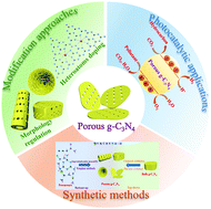
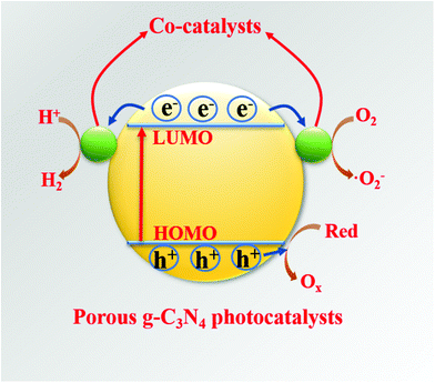
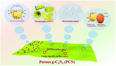
The ability of the PCN design strategy to enhance the photocatalytic activity of g-C3N4 is undeniable, and PCN has rapidly developed in recent years. Although several reviews about mesoporous g-C3N4 (mpg-C3N4) have been reported,37–39 the emerging modification methods and photocatalytic applications, such as supramolecular assembly and photocatalytic reduction of CO2, are undisclosed because of the rapid development of PCN. A review on the recent development of PCN is urgently needed to further promote its advancement. Hence, we summarized the development of carbon nitride in photocatalysis in recent years. Fig. 1 briefly describes the core content of this review, including the synthesis methods, structures and properties, and photocatalytic applications of PCN photocatalysts. First, the methods to prepare PCN are classified into the following two approaches: bottom-up approaches, such as template methods and supramolecular assembly; and top-down approaches, such as chemical exfoliation and thermal oxidation. Second, the morphological structure and functional modification of PCN are also separately discussed. The photocatalytic mechanisms of PCN with different morphologies and their corresponding photocatalytic functional properties are also described. Third, the applications of unitary PCN and PCN-based photocatalysts in photocatalytic hydrogen production, CO2 reduction, and pollutant degradation are summarized. Finally, the current challenges and future development of PCN/PCN-based photocatalysts are discussed.
2. Synthesis strategies and modification approaches
2.1 Synthesis strategies
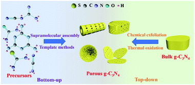
Synthesis methods play a key role in controlling the nanostructures of photocatalysts, including the regulation of the sizes, structures, and morphologies of photocatalysts.40–44 Researchers have developed a number of methods for preparing PCN in recent years. Fig. 2 shows that these methods can be divided into two categories according to the type of precursor. The first one is the bottom-up method, which uses a N-containing compound as a precursor to synthesize PCN under the action of a template or intermolecular force. The second one is the top-down method. This method generally uses bulk g-C3N4 as a precursor to synthesize PCN via chemical exfoliation or thermal oxidation. The two methods have advantages and disadvantages. Nevertheless, both methods can prepare the required functional PCN. In this section, we will introduce the application of these two methods in PCN preparation. The typical synthetic methods of PCN photocatalysts and their properties are listed in Table 1.| Synthetic method | Precursor | Morphology of PCN | Surface area (m2 g−1) | Bandgap (eV) | Additional features | Ref. |
|---|---|---|---|---|---|---|
| Hard template methods | Dicyandiamide and colloidal silica | Mesoporous sheets | 298.3 | 2.66 | The introduction of cyano and hydroxyl groups | 46 |
| Dicyandiamide and SBA-15 silica | Highly ordered nanorod arrays | 71.48 | 2.80 | K–I co-doping | 144 | |
| Soft template methods | Thiourea and NH4Cl | Mesoporous sheets | 126.7 | 2.67 | S-Doping | 51 |
| Dicyandiamide and Triton X-100 | Nanoporous sheets | 299 | — | Comparison of different soft templates | 52 | |
| Supramolecular assembly | Melamine and cyanuric acid | Porous few-layer sheets | 164.2 | 2.75 | N vacancy | 37 |
| Melamine | Nanoporous sheets | 55 | 2.58 | O-Doping | 125 | |
| Melamine and cyanuric acid | Flower-like structure | 235.85 | 2.65 | P-Doping | 192 | |
| Chemical exfoliation | Dicyandiamide and phosphoric acid | Porous sheets | 55.4 | 2.74 | Protonated | 70 |
| Thermal oxidation | Dicyandiamide | Porous sheets | 306 | 2.97 | The thermal oxidation process is explained in detail | 75 |
| Chemical and thermal oxidation | Melamine & HNO3, H2SO4 | Porous ultrathin sheets | 109.30 | 2.95 | O-Doping | 79 |
2.1.1.1 Templating methods. In the early stage of PCN development, template-assisted synthesis is an easy and effective method for PCN preparation. To date, the template-assisted method still has great advantages in controlling its size, porous structure, and morphology. In general, the architectures of the as-prepared samples are directly related to the template structure. An ideal template should have the following characteristics. (i) Excellent architectures, such as uniform porous structures and nanosheet or nanotube structures, are required. (ii) No side reaction should take place between the template and the sample. (iii) The template should be easily removable by green approaches (if necessary). The template-assisted method can be divided into hard and soft template approaches depending on the template selected.
Fig. 3 shows a simple schematic of the preparation processes of these two approaches.
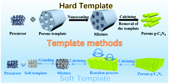 | ||
| Fig. 3 Schematic illustration of porous g-C3N4 prepared by template methods. The template methods can be divided into two categories: hard template and soft template methods. | ||
Hard template methods. The first preparation of PCN using the template method dates back to 2006; Groenewolt and coworkers47 successfully prepared PCN with uniform specifications by using porous silica and cyanamide as the hard template and precursor. To date, several studies have focused on PCN preparation by the hard template method. The intrinsic principle for synthesizing PCN by using the hard template method is achieved via nanocoating. In other words, the precursor is coated to fill the hard template. Accordingly, the morphology, size, and porous structure of PCN can be accurately controlled under the action of the hard template. The planar atomic structure and crystallinity would not be destroyed because of the chemical inertness of the hard template. The hard template method for preparing PCN is divided into three steps: (i) hard template preparation or selection; (ii) targeted material coating over the hard template; and (iii) hard template elimination. However, none of these three steps can achieve satisfactory progress in practical application. First, the surface properties, such as conductivity and surface functional groups, of the hard template may resist the compatibility between the template and the targeted material. Consequently, the coating process is broken. Second, the material coating is a self-assembly process, so an evenly coated targeted material on the hard template is unguaranteed. This situation will lead to the deviation of the material morphology. Finally, the removal of the hard template is generally carried out by using a strong base or acid, such as NaOH, HF, and NH4HF2 solution,48–50 which is harmful to the environment.
The selection of the hard template is based on the surface properties of the targeted material. No functional groups are present on the hard template surface that can react with the precursor or product. Otherwise, the product properties will be affected. The hard template method is divided into two types according to the reaction principle. The first one is the precursor-coating method, which is the same method on the hard template, to generate a pore structure similar to the template. The other one is the hard template-coating method, which primarily covers the precursor with hard template particles. The generated porous products are correlated with the nanoparticle size.
The precursor-coating method can also be divided into two methods according to whether or not to remove the template. The first one involves removal of the hard template; such hard templates include porous silica (SBA-15, KIT-6, and colloidal silica), Ni-foams, and porous anodic aluminum oxide membranes (AAOM).51–53 For example, Zhang et al.54 successfully synthesized PCN with in situ structural defects by using colloidal silica (SiO2) and dicyandiamide (DCDA) as the hard template and precursor, respectively, in which homogeneous solutions of the colloidal silica and DCDA were crucial for the PCN synthesis. Fig. 4a shows that in a typical preparation process of the hard template method a water bath method was applied to prepare white interconnected complex composites by isothermal aging self-assembly. In this process, DCDA was uniformly coated in the colloidal silica to form the composites. Thereafter, the composites were heated under a N2 atmosphere to synthesize PCN/SiO2 composites. Finally, PCN was obtained after SiO2 was removed by using NH4HF2 solution. The characterization results (Fig. 4b–f) showed that the specific surface area (SBET) of the as-prepared PCN can be up to 298.30 m2 g−1. The corresponding pore sizes were primarily approximately 12 nm, which is consistent with the pore diameters of the colloidal silica particles. This porous architecture has two advantages in improving the photocatalytic activity of PCN. (i) It increased the specific surface area of the as-prepared PCN, resulting in an increased number of active sites and light-harvesting capacity. (ii) This interconnected network structure is beneficial to the acceleration of the transport of photogenerated charge carriers. The porous silica (SBA-15, KIT-6, and colloidal silica) templates can accurately control the architecture of the as-prepared sample. Therefore, the use of a silicon template to prepare a porous material with a specific size and structure is satisfactory.
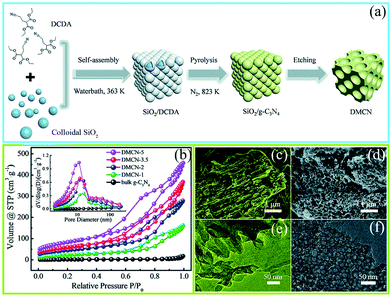 | ||
| Fig. 4 (a) Schematic diagram of the preparation process for mesoporous g-C3N4 (DMCN) samples; (b) N2 adsorption/desorption isotherms and the corresponding pore size distribution curves of different catalysts; SEM images of (c) bulk g-C3N4 and (d) DMCN-3.5 (where 3.5 represents the mass ratio of colloidal SiO2 to dicyandiamide (DCDA)); and TEM images of (e) bulk g-C3N4 and (f) DMCN-3.5. Reproduced from ref. 54 with permission from Royal Society of Chemistry. | ||
Another approach of the precursor-coating method is to retain the hard template. Specifically, another porous photocatalytic material is used as the self-template. This method can still efficiently prepare PCN, and the self-template can also form a heterogeneous junction with PCN. Accordingly, the photocatalytic activity of the prepared samples is improved. For instance, Wei et al.55 successfully prepared PCN by using porous anatase TiO2 microspheres. Typically, amorphous TiO2 microspheres were obtained by treating titanium isopropoxide. Then, porous anatase TiO2 microspheres were prepared by treating amorphous TiO2via a solvothermal method. Thereafter, cyanamide was coated onto the hollow microspheres by a nanocoating procedure. Finally, a porous TiO2/PCN microsphere composite material was obtained by calcining the complex precursor. The porous TiO2/PCN microspheres exhibited uniformity and homogeneity with a pore distribution of 7.1 nm and a surface area of 210.9 m2 g−1. Similarly, Hao et al.56 synthesized a macro/porous g-C3N4/TiO2 composite material. The preparation process is basically similar to the above-mentioned literature except that the porous anatase TiO2 microspheres and cyanamide are replaced by amorphous macro/porous TiO2 powders and melamine, respectively. The specific surface area of the macro/porous g-C3N4/TiO2 composite can be tuned from 39.2 m2 g−1 to 70.2 m2 g−1 by changing the ratio of the amorphous macro/porous TiO2 to melamine. The PCN materials prepared by the aforementioned methods are generally composite materials, which require no removers. This approach is simpler and more environmentally friendly than the other hard template methods. However, this method is limited because of the high requirements for the self-template. First, the material must be a porous structure. Second, the material must have certain thermal stability, and the porous structure must be maintained at least before the precursor is smeared. Few articles have been reported because of the high requirements for templates.
Another hard template approach is the template-coating method. The basic principle of the precursor-coating method is to coat the template with the precursor. The template is then removed to obtain a PCN structure similar to the template structure. The basic principle of the template-coating method is to coat the precursor with the template, then the template is removed to obtain PCN of similar size to the template particles. For example, Wang et al.57 successfully synthesized PCN by using industrial calcium carbonate (CaCO3) nanoparticles and DCDA as the hard template and precursor, respectively. Fig. 5a shows that the CaCO3 nanoparticles are first coated on the precursor and then calcined in a N2 atmosphere. After the CaCO3 particles are removed by HCl aqueous solution, PCN is obtained by continued calcination. This method is “greener” than the traditional silicon template method because of the absence of toxic reagents, and the CaCO3 nanoparticles can be easily removed by diluting the HCl solution. Moreover, CaCO3 is comparatively low-cost and readily available than silicon template materials.
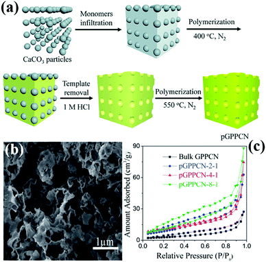 | ||
| Fig. 5 (a) Scheme for preparation of porous 2D graphite-phase polymeric carbon nitride (pGPPCN) using CaCO3 particles as the template; (b) SEM image of pGPPCN-m-n (340 nm) with m/n = 2/1 (where 340 nm represents the average size of CaCO3 particles; m/n represents the mass ratio of dicyandiamide (DCDA) to CaCO3 particles); and (c) the corresponding nitrogen adsorption–desorption isotherms of the as-prepared samples. Reproduced from ref. 57 with permission from Royal Society of Chemistry. | ||
The hard template method has great potential in controlling the morphology, size, and porous structure of PCN. However, the use of toxic removers and the complexity of synthesis routes limit the development of hard templates. Therefore, further study of hard templates that can be easily removed or even not removed is one of the key points in the preparation of PCN by the hard template method.
Soft template methods. During the rapid development of hard templates, the soft template method has also attracted wide attention because of its simple preparation process and no template removal. To date, the aforementioned method has established many species, including amphiphilic block polymers, surfactants, and bubbles.58 However, the amphiphilic block polymer method is rarely used because of its operation complexity. The soft template methods are still primarily divided into the surfactant and bubble methods. These two methods are relatively simple to operate, and the soft template will self-remove during the reaction process. Therefore, the rational design and preparation of PCN can be achieved by using different soft templates and precursors.
The intrinsic principle of the bubble method for synthesizing PCN is attributed to the bubble template generation. Specifically, the soft template releases gases during the calcination of the precursor. These released gases can optimize the reaction heat transfer at high temperatures and act as a template to promote the formation of porous structures. Soft templates, such as DCDA, urea, thiourea, and NH4Cl, used to bubble templates are generally relatively cheap. For instance, Zhou et al.59 prepared different PCN by using thiourea and NH4Cl as the precursor and soft template, respectively. Fig. 6a shows that different ratios of thiourea and NH4Cl were mixed and ground to form solid mixtures. These mixtures were then calcined in a muffle furnace. During calcining, ammonia and hydrogen chloride were obtained by thermal decomposition of ammonium chloride. When released, these gases leave a porous structure in g-C3N4, thus promoting the formation of PCN. The surface area of the as-prepared PCN can reach 126.7 m2 g−1, which is ten times that of bulk g-C3N4 (BCN) (12.1 m2 g−1). However, the gases released (NH3, HCl) by the bubble template are ultimately harmful to the environment, even though this method involves a simple operation and low cost. Therefore, the development of green and pollution-free bubble soft templates is the focus of the following work.
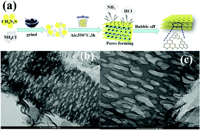 | ||
| Fig. 6 (a) Formation of porous sulfur-doped g-C3N4 (PCNS) and (b and c) TEM images of PCNS. Reprinted with permission from ref. 59. Copyright (2019) American Chemical Society. | ||
The surfactant method is another approach that uses a soft template to prepare PCN. This method requires the template to be applied as a surface agent to the precursor. Wang et al.60 first explored the application of various surfactants in PCN preparation. Although the as-prepared samples had large specific surface areas, porous structures were found in only a few samples, such as in cases of Triton X-100 and ionic liquids. Consequently, a suitable surfactant has become a top priority of the surface agent method. The method requires that the surface agent has certain thermal and chemical stability and can be decomposed during the formation process of carbon nitride. Fan et al.61 then discussed the effect of different temperatures on surfactants. In a typical preparation process, Triton X-100-modified-melamine sulphate (MST) was first prepared by treatment in an oil bath. And then, different PCN samples were obtained by calcining the MST at different temperatures. The experimental results show that the specific surface area of the samples increased with the increase of calcination temperature. However, the photocatalytic activity of the samples did not improve with the increase of specific surface area. The reason for this phenomenon is that the band gap is also one of the important factors affecting their photocatalytic activity. Therefore, balancing the specific surface area and band gap is one of the important methods to improve the PCN photocatalytic activity.
The soft template method has fewer synthesis procedures than the hard template method. The former has several advantages, such as simple equipment, easy operation, and low cost. Exploration of new templates is important for the further application of the soft template method for the preparation of PCN. Nevertheless, the soft template method cannot always strictly control the size and morphology of the porous products, resulting in limitations of the catalytic performance of the final PCN products. The chemical instability of the soft template may also cause side reactions with the precursor, which may affect the product's photocatalytic activity. Therefore, developing a green synthesis route to obtain PCN with high performances by soft template methods still remains a challenge.
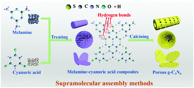
2.1.1.2 Supramolecular assembly. The use of toxic removers and the presence of side reactions have greatly limited the utilization of template methods, even though they have received extensive attention in the past few decades. In recent years, molecular self-assembly has been proposed as an alternative template method for preparing PCN to solve these problems. The molecular self-assembly method can easily control the carbon nitride morphology through hydrogen bonds compared with the template method. Fig. 7 shows that hydrogen bonds play a central role in molecular self-assembly because of their specificity and reversibility.62,63 During calcining, hydrogen bonds are released, resulting in high degrees of freedom and well-defined porous structures.64
A common supramolecular aggregate is a cyanuric acid–melamine (CM) complex. The presence of three hydrogen bonds in the CM complex enables it to adapt to a variety of forms, resulting in different structures in various solvents. For example, Shalom et al.65 synthesized PCN with different morphologies by changing the condensation time using a supramolecular assembly approach. The experimental results showed that the sample size and aperture are gradually decreased with the increase of calcination time. This occurrence is attributed to the specific growth of the CM complex with a pancake-like structure under the action of ethanol solvent and hydrogen bonds. The different treatments of supramolecular aggregates will affect the morphology, structure, and pore size of PCN. For instance, Xiao et al.45 successfully prepared porous few-layer carbon nitride by treating the supramolecular precursor under the action of glycerol and ethanol. Fig. 8a shows that the CM complex is first manufactured in deionized water, and the obtained CM complex has mass functional groups, such as –OH and –NH2, and a large interlamellar distance. This unique feature enabled small ethanol and glycerol molecules to intercalate into the CM layers. After calcining, PCN with fewer layers can be obtained. The obtained sample showed a porous nanosheet structure with a thickness of approximately 1 nm (Fig. 8b–f). The XRD and NMR analysis demonstrated the successful synthesis of g-C3N4 (Fig. 8g and h). The XPS results proved the existence of nitrogen defects in porous few-layer carbon nitride (Fig. 8i). The surface area of the as-prepared porous few-layer carbon nitride was calculated to 164.2 m2 g−1, which is a 14-fold increase relative to BCN (Fig. 8j).
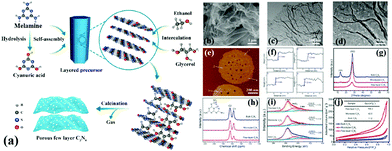 | ||
| Fig. 8 (a) Schematic representation of few-layer C3N4; (b) SEM image of the few-layer C3N4; (c) TEM image of the few-layer C3N4; (d) magnified TEM image of the few-layer C3N4; (e and f) AFM image and the corresponding height profiles along the white lines in e of the few-layer C3N4; (g) XRD patterns, (h) solid-state 13C MAS NMR spectra, (i) N 1s XPS spectra, and (j) N2 sorption isotherms of bulk C3N4, microtube C3N4 and few-layer C3N4. Reprinted with permission from ref. 45. Copyright (2019) American Chemical Society. | ||
To date, supramolecular self-assembly methods have become one of the potential options for preparing micro-nanostructures because of the strong direction and saturation of intermolecular hydrogen bonds.66,67 Molecular self-assembly is generally favourable in water solvents to form stable, regular, and large-sized supramolecular precursors containing hydrogen bonds. However, supramolecular precursors, such as the CM complex, can only self-assemble in organic solvents at room temperature.64,68 Although solvents can affect the dynamic and equilibrium geometry behaviour of the monomers, they cannot offer a homogeneous chemical environment to promote molecular self-assembly.65,69 Although water solvents can be replaced by dimethylsulfoxide and chloroform as they dissolve melamine and cyanuric acid at room temperature, their application is limited by their toxicity.70–72 Therefore, developing a green and easy synthesis route to obtain PCN with high performances via supramolecular assembly approaches still remains a challenge.
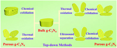
2.1.2.1 Chemical exfoliation. Many exfoliating agents, including strong acids, ammonia, and other highly oxidizing substances (e.g., H2O2 and K2Cr2O7), can be used in the chemical exfoliation of BCN.73,74 The morphology and porosity of PCN can be controlled by changing the type of etchant and the reaction conditions because of the different reaction mechanisms. For example, hydrophilic functional groups, such as –OH, –C
![[double bond, length as m-dash]](https://www.rsc.org/images/entities/char_e001.gif) O, and –COOH, will be embedded in the carbon nitride interlayers under K2Cr2O7–H2SO4 solution treatment.75 Subsequently, these O-containing functional groups are decomposed or converted into quinone groups, resulting in the formation of porous structures.76,77 Shi et al.78 developed a chemical exfoliation method to fabricate PCN nanosheets under the action of phosphoric acid (H3PO4). As shown in Fig. 10, BCN was first protonated by mixing it with the H3PO4 solution and heating. Then, the H3PO4 molecules were embedded in the carbon nitride layers, thereby attaching to the strand of N atoms because of Brønsted acid/base interaction. A porous structure of the PCN sheets was obtained after slow oxidation, which possessed abundant catalytically active sites, thus improving their photocatalytic efficiency.
O, and –COOH, will be embedded in the carbon nitride interlayers under K2Cr2O7–H2SO4 solution treatment.75 Subsequently, these O-containing functional groups are decomposed or converted into quinone groups, resulting in the formation of porous structures.76,77 Shi et al.78 developed a chemical exfoliation method to fabricate PCN nanosheets under the action of phosphoric acid (H3PO4). As shown in Fig. 10, BCN was first protonated by mixing it with the H3PO4 solution and heating. Then, the H3PO4 molecules were embedded in the carbon nitride layers, thereby attaching to the strand of N atoms because of Brønsted acid/base interaction. A porous structure of the PCN sheets was obtained after slow oxidation, which possessed abundant catalytically active sites, thus improving their photocatalytic efficiency.
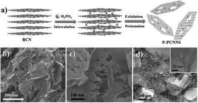 | ||
| Fig. 10 (a) Illustration of the preparation process of protonated porous carbon nitride nanosheets (P-PCNNS); (b and c) SEM images of P-PCNNS; and (d) TEM and HRTEM images of P-PCNNS. Copyright (2015) Wiley. Used with permission from ref. 78. | ||
The exfoliation agents of chemical exfoliation methods, to date, are K2Cr2O7 + H2SO4,75,79 HNO3 + H2SO4,80 and KMnO4 + H2SO4.80 These agents are structurally PCN damaged and environmentally hazardous. Some simple and strong acids, such as HCl, HNO3, and H2SO3, are insufficient to etch BCN into g-C3N4 nanosheets.81,82 Therefore, PCN preparation by the chemical etching method needs to be further improved.
2.1.2.2 Thermal oxidation. Researchers have long wanted to use Hummers’ method for preparing g-C3N4 nanosheets because of the similar structures of g-C3N4 and graphene. However, the hydrogen bonds in carbon nitride frameworks have limited this approach because Hummers’ method cannot directly break the hydrogen bond from bulk g-C3N4 frameworks to prepare g-C3N4 nanosheets. Nonetheless, Niu et al.83 found that thermal oxidation could break the hydrogen bonds in carbon nitride frameworks, resulting in the formation of g-C3N4 nanosheets. The obtained sample has a large specific surface area (306 m2 g−1) and a thin sheet structure (ca. 2 nm). Nonetheless, a large number of interface defects are also formed along with the sheet structure,84 resulting in an undesirable photocatalytic activity. The g-C3N4 obtained by this method has no porous structure. Consequently, the preparation of PCN by thermal oxidation requires other treatments, such as atmosphere-assisted85 and chemical exfoliation.86,87 For example, She et al.87 successfully prepared PCN by thermal oxidation and chemical exfoliation. Fig. 11 shows that the BCN was first synthesized by directly heating melamine. The BCN was then oxidized to carbon nitride nanosheets by thermal oxidation and a porous structure was obtained via chemical exfoliation. The experimental results showed that the photocatalytic performance of PCN was 71 times higher than that of BCN, which was attributed to its large BET specific surface and increased bandgap.
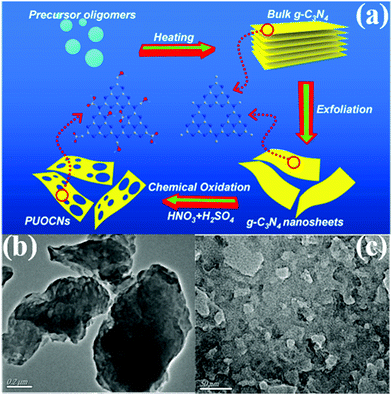 | ||
| Fig. 11 (a) Schematic illustration of preparing 2D porous ultrathin oxygen-doped g-C3N4 nanosheets (PUOCNs); and typical TEM images of (b) bulk g-C3N4 and (c) PUOCNs. Reprinted from ref. 87, Copyright (2015), with permission from Elsevier. | ||
The preparation of PCN by thermal oxidation and chemical corrosion can destroy the structure of PCN, and the synthesis process can also harm the environment. Moreover, this top-down approach always requires high-quality bulk g-C3N4 to act as a precursor, and is complex and time-consuming. The disadvantages of the bottom-up method are obvious compared with the top-down one. Preparation of PCN by supramolecular self-assembly methods is convenient and easy. If the solvent problem in the supramolecular self-assembly method is solved, then it will become a potential method in the preparation of micro-nanostructured materials.
2.2 Modification approaches
PCN has been widely used as an ideal photocatalyst because it has a large number of active sites and large specific surface area. With the development of PCN, the photocatalytic performance of porous carbon-based photocatalytic materials is gradually improving. In this section, we focus on the PCN morphology and the influence of its basic modification on its photocatalytic activity.2.2.1.1 Nanotube structures. Tubular nanostructures with a porous morphology can effectively transfer photoinduced carriers along the 1D path, thus improving photocatalytic efficiency.94,95 Many studies on 1D g-C3N4 nanotube materials have been recently reported.96,97 However, in these reports, either the preparation method is complex, or the obtained carbon nitride photocatalytic activity is moderate. This situation limits the application of g-C3N4 nanotube materials. Nevertheless, Wu et al.98 developed a novel method to prepare P-doped g-C3N4 tubes. Fig. 12a shows that DCDA and phytic acid are chosen as the precursor and morphological regulator of PCN, respectively. Different proportions of phytic acid have been used to investigate the synthesis mechanism. When the proportion of phytic acid is small, g-C3N4 exhibits a hollow nanotube structure composed of a large number of nanosheets. When the proportion of hydrochloric acid increases, the nanosheets turn into a flower-like structure. Phytic acid plays a key role in morphological regulation.
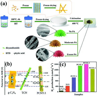 | ||
| Fig. 12 (a) Schematic illustration for the formation of 3D porous P-doped carbon nitride tubes (PCNT); (b) schematic illustration of the band positions for bulk g-C3N4, carbon nitride tube (TCN) and PCNT-3 (where 3 represents the volume of phytic acid (PA) solution) samples, respectively; and (c) H2 production rates of bulk g-C3N4, TCN and samples with different PA ratios. Reprinted from ref. 98, Copyright (2018), with permission from Elsevier. | ||
2.2.1.2 Nanosheet structures. 2D sheet materials have great potential in the field of photocatalysis because of their promising electronic features and unique physical properties. Graphene, a typical 2D sheet material, plays an important role in the field of photocatalysis because of its mechanical robustness, superior charge carrier mobility, and high thermal/chemical stability. Traditional g-C3N4 presents a stacked bulk structure with a specific surface area of 10 m2 g−1, which affects the photoelectron transfer and thus reduces the photocatalytic activity of g-C3N4.99–103 The preparation of 2D carbon nitride sheets is one of the effective methods to modify carbon nitride.
At present, the main methods of preparing carbon nitride sheets are thermal oxidation,11 chemical etching,104 sonication exfoliation105 and supramolecular self-assembly.45 Among these methods, supramolecular self-assembly has attracted great attention because of its simple operation. The traditional melamine–cyanurate acid (MCA) complex is prepared by mixing melamine and cyanuric acid as precursors in solvent. However, the use of solvent limits the mass preparation of the MCA complex. Liu et al.106 developed a novel supramolecular precursor to prepare mpg-C3N4 nanosheets. The novel supramolecular precursor is prepared by hydrothermal treatment of DCDA to form the MCA complex. The MCA complex prepared by this method has a similar structure to the conventional one self-assembled from melamine and cyanuric acid. However, the properties of PCN prepared by these methods are quite different. Fig. 13 shows that HCN (PCN prepared by a novel supramolecular precursor) has a narrower bandwidth and higher photocatalytic activity than MCN (PCN prepared using the conventional supramolecular precursor). The experimental results show that this phenomenon is due to the enhanced HCN π-conjugated system. Accordingly, the transfer of photogenic carriers is promoted, and the photocatalytic activity is improved.
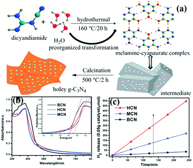 | ||
| Fig. 13 (a) Schematic illustration for the preparation of 3D holey g-C3N4 nanosheets by annealing the precursor obtained by the hydrothermal pre-treatment of dicyandiamide (DCDA); (b) UV-vis diffuse reflectance spectra of bulk g-C3N4 (BCN), holey g-C3N4 nanosheets (HCN) and g-C3N4 nanosheets obtained by the melamine–cyanurate complex (MCN); and (c) photocatalytic hydrogen revolution rate (HER) plots of BCN, HCN and MCN. Reprinted from ref. 106, Copyright (2018), with permission from Elsevier. | ||
2.2.1.3 Nanosphere structures. 3D PCN with nanosphere structures can reduce the migration path of carriers from the interior to the surface in all directions and improve the photocatalytic activity of carbon nitride.107–109 Zhao et al.110 successfully synthesized hollow mpg-C3N4 nanospheres through a one-step soft-template method. The obtained samples possessed a large amount of porous structures with a high surface area. Consequently, the light absorption in the visible range increased, and the separation rate of photoinduced carriers accelerated. Si et al.111 developed a hard template method to prepare crystalline nanoporous g-C3N4 microspheres (Np-CNMs). Fig. 14 shows that HM-SiO2 and cyanamide are used as the hard template and precursor of Np-CNMs, respectively. A series of Np-CNM samples was synthesized by adjusting the N2 atmospheric pressure. In comparison with BCN, the DRS curve of Np-CNMs has a new absorption band at 550 nm, which may correspond to n–π* electron transitions in the conjugated aromatic system. The appearance of this new absorption band improves the absorption range of Np-CNMs in the visible-light region. The photocatalytic activity of Np-CNMs is 40 times that of BCN owing to these favourable characteristics.
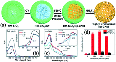 | ||
| Fig. 14 (a) Illustration of the synthesis of crystalline nanoporous g-C3N4 microspheres (Np-CNMs); (b and c) UV-vis spectra and bandgaps of bulk g-C3N4 and Np-CNMs; and (d) photocatalytic H2 production rates under visible-light irradiation (λ ≥ 420 nm) of Np-CNMs and bulk g-C3N4, respectively. Reproduced from ref. 111 with permission from Royal Society of Chemistry. | ||
The mechanisms of improving the photocatalytic activity of PCN are different for different morphologies and structures. For example, the mechanism of the PCN with a nanorod structure that improves the photocatalytic activity of carbon nitride is to broaden the absorption area of the visible-light region.98 By contrast, the mechanism of the PCN with a nanosheet structure is to narrow the bandwidth for improving its ability to absorb light.106 The PCN microsphere structure introduced an n–π* electron transition system to promote the transfer of photogenic carriers.101 In practical application, we can choose the type of pore shape of carbon nitride according to the actual situation.
2.2.2.1 Element doping. Element doping is confirmed to be an indispensable method for simultaneously achieving effective photogenerated charge carrier separation and a widened light-harvesting range.117–126 Suitable foreign atoms introduced into the carbon nitride framework can adjust the band gap of g-C3N4 through the hybridization of atomic orbitals. Element doping will also promote the separation of photogenic electrons because of the influence of electronic polarization.127–129 To date, many heteroatoms, including non-metal elements (such as S, O, B, P and halogens)96,114,130–136 and metal elements (Fe, Cu, Co and Mn),137–140 have been successfully incorporated into PCN frameworks, and the corresponding photocatalytic activity is enhanced. Herein, we will introduce the synthesis methods and the principles for enhancing the photocatalytic activity of nonmetal- and metal-doped PCN photocatalysts.
B Doping. The B–C functional group can be used as a Lewis acid site to increase the number of active sites in the photocatalytic process because B has similar size and chemical characteristics to C. The photocatalytic activity of carbon nitride can be effectively improved by introducing B into the g-C3N4 framework. For example, Wang et al.141 successfully synthesized B-doped g-C3N4 with a hollow tube structure by using MCA as a supramolecular precursor. The B-doped g-C3N4 has a narrow band gap, which broadens the light absorption range of carbon nitride. The hollow tubular structure can reflect the incident light many times. Accordingly, the absorption ability of carbon nitride is improved. These characteristics play key roles in improving the photocatalytic activity of B-doped carbon nitride.
O Doping. Doping with non-metal atoms will change the partial electronic structure of carbon nitride. This process is carried out to improve the visible-light absorption ability and promote the effective separation of photogenic carriers. Doping with O atoms can play a key role in these areas.127,142–146 In general, O-doped g-C3N4 is prepared in a hydrogen peroxide or an O2 atmosphere. However, Zhang et al.135 prepared porous and O-doped g-C3N4 by hydrothermal and thermal treatment. Fig. 15a shows that under the hydrothermal conditions, melamine spontaneously forms the MCA complex and introduces C
![[double bond, length as m-dash]](https://www.rsc.org/images/entities/char_e001.gif) O functional groups to lay a foundation for preparation of O-doped g-C3N4. The experimental results show that the O-doped g-C3N4 has a narrower band gap (Fig. 15d) and higher photocatalytic activity (Fig. 15c) than those of g-C3N4. These characteristics are attributed to the change in the local electronic structure of the carbon nitride because of the doping with O atoms.
O functional groups to lay a foundation for preparation of O-doped g-C3N4. The experimental results show that the O-doped g-C3N4 has a narrower band gap (Fig. 15d) and higher photocatalytic activity (Fig. 15c) than those of g-C3N4. These characteristics are attributed to the change in the local electronic structure of the carbon nitride because of the doping with O atoms.
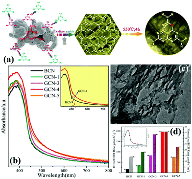 | ||
| Fig. 15 (a) Illustration of the fabrication of O-doped porous g-C3N4 from a hydrogen bond-induced supramolecular precursor assembled under hydrothermal treatment; (b) UV-vis absorption spectra of bulk g-C3N4 and GCN; (c) TEM image of GCN-4 (where 4 indicates that the Teflon-lined stainless-steel autoclave is sealed and heated at 200 °C under continuous magnetic stirring of 100 rpm for 4 h); and (d) overall and normalized HER rates of bulk g-C3N4 and GCN, and wavelength-dependent AQY of GCN-4 (inset). Reprinted from ref. 135, Copyright (2017), with permission from Elsevier. | ||
S Doping. S-Doping is also an efficient strategy to narrow the energy gap and increase the visible-light response of PCN. Zhou et al.59 prepared S-doped g-C3N4 with a porous network by using thiourea and NH4Cl as the precursor and bubble template, respectively. In a typical process, the different ratios of thiourea and NH4Cl were mixed and ground to form solid mixtures. These mixtures were then calcined in a muffle furnace. During the process of calcination, ammonia and hydrogen chloride obtained by thermal decomposition of ammonium chloride affect the thermal polymerization of thiourea, thus promoting the formation of a porous structure. Considering the doping with heterogeneous atoms, the Fermi level of g-C3N4 is lowered, thereby promoting the photogenic electron transfer. Moreover, g-C3N4 has substantial active sites and large specific surface area because of the existence of the porous structure. Therefore, the obtained well-modified S-doped g-C3N4 displaying excellent photocatalytic performance benefited from these characteristics.
P Doping. For non-metal element doped g-C3N4, the reported of phosphorus doped g-C3N4 is much less than that of the other elements. This phenomenon is attributed to the obscured phosphorus doping mechanism for improving the photocatalytic activity. In addition, phosphorus precursors can only partially meet the practical application requirements. Deng et al.147 successfully prepared phosphorus-doped g-C3N4 ultrathin nanosheets with a porous structure (PCN-S) by a thermal exfoliation method. The experimental results show that PCN-S has a large surface area and abundant in-plane pores on its surface, which broaden its light absorption region to the whole visible light range. Different phosphorus doping ratios will obtain PCN-S with different pore sizes, and the pore structure played a key role in improving its photocatalytic activity. The PCN-S photocatalyst has potential for the treatment of Cr(VI)/2,4-DCP or other organic pollutants in wastewater because of these characteristics.
Metal doping. The recombination rate of photogenerated carriers on the surface of g-C3N4, a non-metal photocatalyst, is much higher than those of metal-based photocatalysts. On this basis, metal-doped g-C3N4 has become a major research topic, and it can provide a new strategy to design and prepare novel visible-light-driven photocatalysts. To date, various metal elements have been doped into g-C3N4.148,149 Metal-ion doping is a favourable way to change the energy band structure of g-C3N4, which can broaden the energy band structure and enhance the separation of photogenerated charge carriers.58 For example, Wang et al.138 synthesized a porous Mn-doped g-C3N4 photocatalyst through the calcination–refluxing method. Density functional theory manifests that the modification of the carboxyl group and Mn doping affect the molecular orbital distribution in the g-C3N4 frameworks. This situation accelerates the photoelectron migration and prevents the recombination of the photogenerated carriers. Le et al.137 developed a series of Cu-doped mesoporous g-C3N4 (mpg-C3N4) photocatalysts by using melamine and cupric chloride as precursors through a hard-templating method. Similarly, Cu doping affects the optical properties of g-C3N4, narrows its band gap, enhances its light absorption capacity, and improves its photocatalytic activity.
Dual element-doping. The photocatalytic activity of PCN can be improved by doping it with non-metal and metal elements because they can adjust the band gap structure and facilitate the separation of photogenerated electrons.150–153 However, doping with a single element cannot overcome the disadvantages of g-C3N4. The enhancement in photocatalytic activity of dual element-doped PCN has been recently proposed.132,154–156 For example, Guo et al.154 successfully prepared mpg-C3N4 co-doped with K and I through a hard template by using DCDA and KI as the precursors. The experimental results show that K and I play different roles in the g-C3N4 framework. The I ions primarily cause the absorption edge of g-C3N4 to red shift, whereas the K ones primarily promote the transfer of photogenic electrons and thus inhibit the recombination of the photogenerated carriers. Wu et al.155 prepared Co and Mo element co-doped mpg-C3N4 (Co/Mo-MCN) via a template-free approach by using CoCl2 and MoS2 as the precursors. Relative to pristine g-C3N4 and mono-metal-doped g-C3N4 (Co-MCN and Mo-MCN), the as-prepared Co/Mo-MCN exhibited a significantly high photocatalytic activity because of the synergy between Co and Mo.
Element doping is primarily aimed at the bandwidth structure of photocatalysts and surface photoelectron transfer. This process can narrow the bandwidth and facilitate the transfer of the photogenic electrons. This issue is important in the modified g-C3N4 strategy. However, the doping mechanism and site of some elements, such as P, and certain metal elements are obscured, which need further study.
2.2.2.2 Hybridization. Primary PCN can improve the photocatalytic activity primarily in the morphological, structural, and elemental compositions. Different morphologies have a great influence on the photocatalytic activity. The photocatalytic activity is significantly increased by element doping; for instance, doping with O element will break the symmetry of g-C3N4, thus promoting the separation of photogenerated electron–hole pairs. Some structural defects also act as capture sites to obtain photogenerated electrons, thus accelerating the separation of the photogenerated electron–hole pairs. If the modified PCN can be combined with other materials, then the photocatalytic activity can be enhanced. In this section, we primarily introduce the effect of hybridization on PCN-based photocatalysts.
Hybridization is one of the important means to promote the separation of photogenerated charge carriers.157–169 In many reports, PCN hybridization strategies are divided into two types: the first one is the hybridization between PCN and a co-catalyst; the other one is the hybridization between PCN and a photocatalyst. The two hybrid methods promote photogenic carrier separation in slightly different ways. Fig. 16 shows the mechanism of improving the photocatalytic activity over a PCN/co-catalyst composite photocatalyst. Under light, the PCN is excited to produce photogenerated electrons and holes. The co-catalyst can accelerate the transfer of the photogenerated electrons because of its superior conductivity or its ability to store electrons for achieving the separation of the photogenerated electron and hole pairs. The hybridization of PCN and a photocatalyst can also be divided into three types: n–n heterojunction, p–n heterojunction, and Z-type heterojunction. The mechanisms of improving the photocatalytic activity over the former two heterojunctions are similar. Fig. 17 shows that under light the two types of photocatalysts are stimulated to produce photogenerated electrons which will be transferred from the photocatalyst with a low conduction band (CB) potential to another photocatalyst, while the photogenerated holes will be transferred from the photocatalyst with a positive valence band (VB) potential to another photocatalyst. Consequently, the photogenerated electrons and hole pairs are separated. In contrast to n–n and p–n heterojunctions, the photogenerated electrons in the CB with a higher potential migrate to the VB with a lower potential, thus achieving the separation of the photogenerated electrons and holes.
p–n heterogeneous junctions. The electron concentration in the g-C3N4 structure is greater than the hole concentration because g-C3N4 is an n-type photocatalyst. When n-type carbon nitride and a p-type photocatalyst (the hole concentration in the structure is greater than the electron concentration) recombine, a p–n junction will be formed, thereby greatly promoting the separation of photogenic electron–hole pairs.170,171 Jiang et al.171 successfully fabricated a p–n heterojunction between n-type Pg-C3N4 and p-type BiOI by an in situ growth method. Fig. 18 shows that the introduction of p-type BiOI broadens the visible-light absorption range of PCN. The visible-light absorption range gradually increases with the increase of carbon nitride concentration. The formation of a heterojunction can accelerate the photogenerated electron transfer from carbon nitride to BiOI and promotes the separation of photogenerated charge carriers. The photocatalytic activity of the PCN/BiOI composite photocatalyst was almost 5.3 and 4.2 times higher than that of BiOI and PCN, respectively, owing to these properties.
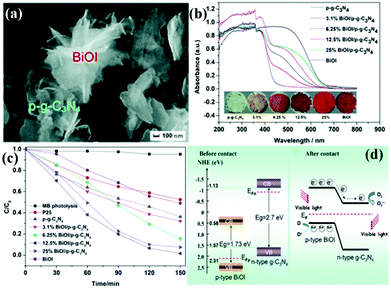 | ||
| Fig. 18 (a) SEM image of the as-prepared 12.5% BiOI/porous g-C3N4 (p-g-C3N4) samples (where 12.5% represents the BiOI content); (b) UV-vis DRS, the corresponding colours of p-g-C3N4, BiOI, and BiOI/p-g-C3N4; (c) photocatalytic degradation of MB as a function of irradiation time over p-g-C3N4, BiOI, and BiOI/p-g-C3N4 samples under visible light irradiation; and (d) diagrams of the energy bands of BiOI and p-g-C3N4 before contact and the formation of a p–n junction and the proposed charge separation process of BiOI/p-g-C3N4 heterostructures under visible-light irradiation. Reproduced from ref. 171 with permission from Royal Society of Chemistry. | ||
n–n heterogeneous junctions. Considering the actual situation, only a few p-type photocatalysts can form an interlacing p–n heterojunction with PCN. The main PCN-based heterojunction is an n–n heterojunction.172–175 Liang et al.176 developed a novel n–n heterojunction between mesoporous g-C3N4 and binary metal sulphide (mpg-C3N4/SnCoS4) through an in situ hydrothermal method. As shown in Fig. 19, the experimental results indicated that the SnCoS4 nanoparticles supported mpg-C3N4 with an ordered mesoporous structure, providing additional reaction active sites and large contact areas for the adsorption and degradation of pollutants. The photocatalytic activity is demonstrated by the degradation of rhodamine B (RhB) and methylene blue (MB). The enhanced photocatalytic degradation of RhB and MB should be attributed to the formation of an n–n type heterojunction between mpg-C3N4 and SnCoS4. The incorporation of SnCoS4 into mpg-C3N4 can decrease the band gap of mpg-C3N4, changing the CB and VB potentials, improve the photogenerated interfacial charge transfer, and enhance the separation of charge carriers under the photocatalytic reaction.
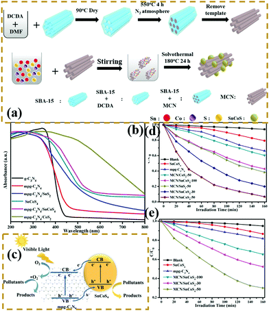 | ||
| Fig. 19 (a) Schematic illustration for the preparation of a mesoporous carbon nitride (mpg-C3N4)/SnCoS4 heterojunction; (b) UV-vis diffuse reflectance spectra of g-C3N4, mpg-C3N4, SnCoS4, mpg-C3N4/SnCoS4, mpg-C3N4/CoS2 and mpg-C3N4/SnS2; (c) schematic of photocatalytic degradation over mpg-C3N4/SnCoS4 under visible light irradiation; and photocatalytic degradation efficiencies of (d) MB and (e) RhB over the as-prepared samples under visible-light irradiation. Reprinted from ref. 176, Copyright (2017), with permission from Elsevier. | ||
Z-scheme heterogeneous junctions. When some heterojunction photocatalysts applied to degradation are insufficient to generate the required oxidation intermediates because of the VB potential, the migration path of the photogenerated electrons will change, that is, migration from the CB to the VB, thus forming Z-type heterojunctions.177–182 As shown in Fig. 20, Huo et al.183 designed a novel 2D/2D porous g-C3N4 (Pg-C3N4)/SnS2 composite photocatalyst by an in situ growth method. The combination of 2D Pg-C3N4 and 2D SnS2 nanosheets can form a large-scale contact interface, resulting in effective separation of interfacial charge carriers and shortening of the charge transmission path. The experimental results showed that the optimized Pg-C3N4/SnS2 composite exhibits enhanced photocatalytic degradation performance, which is 18 and 8 times higher than that of Pg-C3N4 and SnS2, respectively. On the basis of radical-trapping experiments and band structure analysis, the heterojunction between SnS2 and Pg-C3N4 was confirmed to be a Z-scheme heterojunction. The formation of a Z-scheme heterojunction is beneficial to promote the separation of the photogenerated carriers and enhance the redox capacity of the Pg-C3N4/SnS2 composite photocatalyst.
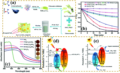 | ||
| Fig. 20 (a) Schematic illustration of the fabrication process for porous graphitic C3N4 (Pg-C3N4)/SnS2 composites; (b) photocatalytic degradation of MB over the as-prepared samples; (c) UV-vis DRS spectra of Pg-C3N4, SnS2 and Pg-C3N4/SnS2 composites; and (d and e) schematic diagrams of the interfacial photo-induced electron–hole pair transfer mechanisms over Pg-C3N4/SnS2 composites. Reprinted from ref. 183, Copyright (2019), with permission from Elsevier. | ||
3. Applications
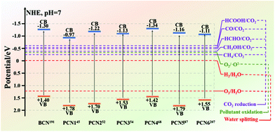
The energy crisis and environmental pollution left by the rapid economic development have been paid great attention by many researchers.126,184–187 The two major problems that need to be solved are determining new energy resources and dealing with environmental pollution. Reports revealed that photocatalysts have great potential in solving these two problems. Such potential includes the use of photocatalysis to produce hydrogen for solving the energy crisis, degrade organic matter, or solve environmental pollution. Among the many photocatalysts, non-metallic g-C3N4 has absolute advantages in many aspects, except for poor photocatalytic activity. These advantages include an appropriate band gap for enabling g-C3N4 to utilize visible light, and chemical stability for preventing carbon nitride from photocorrosion. Therefore, improving the photocatalytic activity of g-C3N4 has become a big challenge at present.For bulk g-C3N4 (BCN), there are three main reasons for the low photocatalytic activity of BCN. First, in the BCN frameworks, the carbon and nitrogen atoms are very hard to separate because of their chemical bonding, which lead to the generation of a delocalized π-conjugated structure and consequently decreases the photocatalytic activity.188,189 Second, hydrogen bonds and amino functional groups in BCN structures act as the recombination sites of photogenerated carriers to promote the recombination of photogenerated electron–hole pairs, thus resulting in fewer photogenerated carriers involved in photocatalytic reactions and decreased photocatalytic activity. Third, the stacked bulk structure extends the transfer path of the photogenerated electrons, so that the photogenerated electrons cannot reach the surface of the photocatalyst to participate in the photocatalytic reaction. Due to these shortcomings, many modification strategies of BCN are proposed to improve its photocatalytic activity. Furthermore, porous g-C3N4 (PCN) preparation stands out among the many strategies and is a more popular one at present. Different preparation methods can produce PCN with different morphologies and structures. As shown in Fig. 21, the bandgap of BCN differs from those of different PCN. Moreover, the energy band positions of PCN and BCN cover the potentials needed for photocatalytic CO2 reduction, photocatalytic water splitting, and photocatalytic pollutant degradation. These results revealed that BCN and PCN have great potential for photocatalytic CO2 reduction, photocatalytic water splitting and photocatalytic pollutant degradation. In this section, we summarize the applications of PCN in photocatalytic CO2 reduction, photocatalytic water splitting, photocatalytic pollutant degradation, and other aspects in recent years (Table 2).
| Photocatalytic application | Sample | Photocatalytic performance of the sample | Photocatalytic performance of bulk g-C3N4 | Light source | Experimental conditions | Ref. |
|---|---|---|---|---|---|---|
| Photocatalytic H2 production | Porous few-layer C3N4 | 7990 μmol g−1 h−1 | 305 μmol g−1 h−1 | Xenon lamp (λ > 420 nm) (300 W) | 20 mg of photocatalyst (1 wt% Pt), 100 mL of an aqueous solution containing 10 vol% of isopropanol | 37 |
| Photocatalytic H2 production | Mesoporous graphitic-like carbon nitride | 1800 μmol g−1 h−1 | 480 μmol g−1 h−1 | Medium pressure Hg arc lamp (125 W) | 100 mg of photocatalyst (0.5 wt% Pt), 100 mL of an aqueous solution containing 10 vol% of isopropanol | 43 |
| Photocatalytic H2 production | Sulphur-doped porous g-C3N4 nanosheets | 380 μmol g−1 h−1 | 72 μmol g−1 h−1 | Xenon lamp (λ > 420 nm) (300 W) | 15 mg of photocatalyst, 20 mL of an aqueous solution containing 10 vol% of TEOA | 51 |
| Photocatalytic H2 production | Hollow mesoporous g-C3N4 spheres | 3140 μmol g−1 h−1 | 94 μmol g−1 h−1 | Xenon lamp (λ > 400 nm) (300 W) | 50 mg of photocatalyst (5 wt% Pt), 100 mL of an aqueous solution containing 10 vol% of TEOA | 100 |
| Photocatalytic BPA degradation | Structure-deficient mesoporous g-C3N4 | Reaction rate = 0.317 min−1 | Reaction rate = 0.008 min−1 | Xenon lamp (420 nm < λ < 780 nm) (300 W) | The optimal dosages of catalysts (0.5 g L−1) and K2S2O4 (1 g L−1) were determined referring to the best degradation activity for BPA and used throughout the experiments unless otherwise specified | 46 |
| Photocatalytic RhB degradation | Macro/mesoporous g-C3N4/TiO2 | Reaction rate = 0.0478 min−1 | Reaction rate = 0.0066 min−1 | Xenon lamp (λ > 420 nm) (350 W) | 40 mg of photocatalyst was suspended in RhB aqueous solution (30 mL, 0.01 mmol) | 48 |
| Photocatalytic RhB degradation | Nanoporous graphitic carbon nitride | Reaction rate = 0.017 min−1 | Reaction rate = 0.0009 min−1 | Xenon lamp (λ > 400 nm) (300 W) | 100 mg of photocatalyst was suspended in RhB aqueous solution (100 mL, 10 mg L−1) | 53 |
| Photocatalytic RhB degradation | Mesoporous hollow g-C3N4 spheres | Reaction rate = 0.062 min−1 | Reaction rate = 0.0062 min−1 | Hg arc lamp (λ > 420 nm) (1000 W) | 1 mg of photocatalyst was suspended in RhB aqueous solution (1 mL, 10 mg L−1) | 60 |
| Photocatalytic CO2 reduction | Protonated porous g-C3N4 nanosheets | 7.4 μmol h−1 (CO-production) | 3.0 μmol h−1 (CO-production) | Xenon lamp (400 nm < λ < 800 nm) (300 W) | 50 mg of photocatalyst was uniformly dispersed on a porous quartos film in a reaction cell, followed by injection of 5 mL solution (MeCN![[thin space (1/6-em)]](https://www.rsc.org/images/entities/char_2009.gif) : :![[thin space (1/6-em)]](https://www.rsc.org/images/entities/char_2009.gif) TEOA = 4 TEOA = 4![[thin space (1/6-em)]](https://www.rsc.org/images/entities/char_2009.gif) : :![[thin space (1/6-em)]](https://www.rsc.org/images/entities/char_2009.gif) 1) 1) |
70 |
| Photocatalytic CO2 reduction | Sb doped SnO2 decorated porous g-C3N4 nanosheets | 22.47 μmol (5 h)−1 g−1 (CO-production) and 2.98 μmol (5 h)−1 g−1 (CH4-production) | 1.07 μmol (5 h)−1 g−1 (CO-production) and 0 μmol (5 h)−1 g−1 (CH4-production) | Xenon lamp (λ > 420 nm) (300 W) | 30 mg of photocatalyst was uniformly dispersed on a porous quartos film in a reaction cell, followed by injection of 5 mL solution (MeCN![[thin space (1/6-em)]](https://www.rsc.org/images/entities/char_2009.gif) : :![[thin space (1/6-em)]](https://www.rsc.org/images/entities/char_2009.gif) TEOA = 4 TEOA = 4![[thin space (1/6-em)]](https://www.rsc.org/images/entities/char_2009.gif) : :![[thin space (1/6-em)]](https://www.rsc.org/images/entities/char_2009.gif) 1) 1) |
129 |
| Photocatalytic CO2 reduction | Porous g-C3N4/Sn2S3-diethylenetriamine | 4.84 μmol h−1 g−1 (CH4-production) and 1.35 μmol h−1 g−1 (CH3OH-production) | — | Xenon lamp (300 W) | 100 mg of photocatalyst was used to reduce CO2 | 195 |
3.1 Application in photocatalytic hydrogen evolution
Traditional energy resources, such as oil, coal, and other reserves, failed to meet the rapid economic development. Solar energy is a new energy source that can be indefinitely used. Solar energy has been widely used in photocatalytic hydrogen production because of the zero pollution and high energy density of hydrogen.190–194 Almost half of the solar energy is visible light, so a g-C3N4 photocatalyst, which can utilize visible light, is a popular photocatalyst at present.However, traditional BCN shows weak photocatalytic activity because of its intrinsic structural defects, high exciton binding energy, few active sites, and small surface area. Photocatalysts with a porous structure and large surface area have a large number of transfer channels of photogenerated electrons and reactive sites, which can increase the density of surface electrons and lengthen the lifetime of charge carriers; this condition promotes the diffusion of photogenerated carriers and enhances their photocatalytic activity.195–199 For example, Bai et al.200 successfully fabricated PCN by an easy hydrothermal method by using urea and melamine as precursors. Fig. 22 shows that a mixture of urea and melamine is hydrothermally treated to obtain a sheet intermediate. The sheet intermediate is then calcined and extracted to release gas for forming a pore structure. The PCN (BCN-U) obtained by this method exhibited porous sheet structures, which significantly expanded the specific surface area and restrained the charge recombination of the modified g-C3N4. The photocatalytic performance results show that the photocatalytic activity of BCN-U is 5.7-fold higher than that of BCN, benefitting from these characteristics. This finding indicates that the photocatalytic activity can be significantly improved by the introduction of porous structures on the g-C3N4 sheet and proves the superiority of the pore structure in the field of photocatalytic hydrogen production.
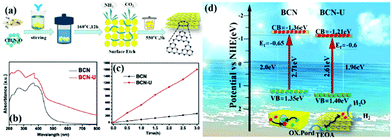 | ||
| Fig. 22 (a) Diagram for the fabrication of porous g-C3N4 nanosheets (BCN-U); (b) UV-vis DRS spectra of bulk g-C3N4 (BCN) and BCN-U; (c) photocatalytic activities of BCN and BCN-U; and (d) band structures and charge separation of BCN and BCN-U. Reprinted from ref. 200, Copyright (2018), with permission from Elsevier. | ||
In addition to increasing the specific surface area and active sites of the samples, the PCN sheets also improve the photocatalytic activity to shorten the photogenerated electron transport path. At this point, PCN nanotubes are different from the others. The PCN nanotubes improve the photocatalytic activity to ensure that the incident light will be reflected many times, thereby increasing the reflection path of light, and promote the absorption of light by the photocatalytic materials. For example, Wang et al.201 developed an easy vapor-deposition method to prepare MCN by using melamine and modified halloysite as the precursor and template, respectively. In comparison with BCN, the encouraging improvement of the photocatalytic hydrogen evolution of MCN can be attributed to the augmentation of specific surface area and the acceleration of charge carrier transfer and separation.
Most previous studies used a hard template method to prepare PCN with a 3D structure. The structure of the resulting samples heavily depends on the hard template structure. For example, Si et al.111 reported that a novel Np-CNM was prepared by using porous silicon as a hard template. However, the hard template method requires removal of certain agents, including HF, NaOH solution, and NH4HF2. This task is harmful to the environment. Nowadays, a new method of using a supramolecular assembly method to prepare PCN with a 3D structure is becoming increasingly popular. For example, Zhao et al.110 successfully synthesized hollow MCNs by a one-step soft templating method. The morphology of the hollow MCNs was controlled by changing the concentration of ionic liquid. The experimental results showed that the as-prepared samples had abundant mesopores with a large specific surface area. This manifestation is attributed to the decomposition of the ionic liquid and the release of volatile domains. The concentration of the solvent and ionic liquid played a key role in the morphology of the as-prepared samples. At low ionic liquid concentration, the as-prepared samples exhibited a hollow mpg-C3N4 spherical structure. By contrast, at high ionic liquid concentration, the CM complex was rearranged to form a flower-like structure. The experimental results showed that the photocatalytic hydrogen evolution reaction rate of the as-prepared hollow mpg-C3N4 sphere samples was almost 30-fold higher than that of traditional BCN. This manifestation may be caused by their large specific surface area and ultrathin nanosheet structure, which are beneficial for promoting light absorption and effective charge separation. Such occurrence may lead to increased photocatalytic H2 evolution rates.
In general, the introduction of surface defects is an effective method to prevent photogenerated carriers from recombining on a photocatalyst surface. Nowadays, surface defects are primarily reflected in structural and N defects.202–205 Urea, melamine, DCDA, and other nitrogenous compounds are the common precursors for the preparation of conventional g-C3N4. Even the g-C3N4 prepared by urea, melamine, DCDA, and other nitrogenous compounds exhibited low photocatalytic activity. However, the modified carbon nitride with high activity can still be prepared by pre-treating urea and melamine. For example, Ruan et al.116 prepared porous defect-rich g-C3N4 by using urea and melamine as the precursor system. A mixture of urea and melamine treated with ethanol can cause structural defects in the product. In this study the structural defects were adjusted by modifying the ratio of urea to melamine. The results showed that the photocatalytic activity of carbon nitride reached a maximum of 3.1 mmol g−1 h−1 with a quantum efficiency of 28% at 420 nm when the ratio of urea to melamine was adjusted to 1![[thin space (1/6-em)]](https://www.rsc.org/images/entities/char_2009.gif) :
:![[thin space (1/6-em)]](https://www.rsc.org/images/entities/char_2009.gif) 2. The increased photocatalytic H2 evolution can be attributed to the larger surface area and more active sites compared with those of BCN.
2. The increased photocatalytic H2 evolution can be attributed to the larger surface area and more active sites compared with those of BCN.
In addition to morphological modification, element doping also plays a key role in improving the photocatalytic activity of hydrogen production of PCN. The introduction of additional atoms can broaden its visible absorption range and modify its electron structure.206 For instance, Yang et al.207 successfully synthesized flower-like P-doped mesoporous g-C3N4 (mpg-C3N4) by a simple supramolecular assembly method. Fig. 23a shows that the CM complex, a supramolecular precursor, was mixed with phosphoric acid. The product was calcined to obtain P-doped mpg-C3N4. The obtained P-doped mpg-C3N4 exhibited a relatively regular flower structure. The prominent photocatalytic hydrogen evolution performance reached 256.4 mmol h−1, which is almost 24-fold higher than that of BCN; this finding is attributed to its broadened visible absorption range and modified electron structure (Fig. 23b–d).
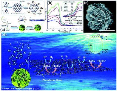 | ||
| Fig. 23 (a) The formation process of phosphorus-doped flower-like g-C3N4 (PCN); (b) UV-vis DRS spectra of carbon nitride samples; (c) SEM image of PCN1.5 (where 1.5 represents the amount of phosphoric acid); and (d) a possible mechanism for the photocatalytic hydrogen evolution reaction with P-doped carbon nitride. Reproduced from ref. 207 with permission from Royal Society of Chemistry. | ||
When two catalysts are combined, the CB and VB of one catalyst are more negative than those of the other catalyst. The two photocatalysts will form a type II heterojunction. For example, Liu et al.208 developed a hard template approach bonded with a hydrothermal method to synthesize mpg-C3N4 nanosheets combined with CdLa2S4 nanocomposites. The obtained CdLa2S4/mpg-C3N4 composites showed significantly enhanced visible-light photocatalytic H2 production activity compared with unitary CdLa2S4 and mpg-C3N4. Fig. 24d shows the possible mechanism of the enhanced photocatalytic H2 production activity. Under visible-light illumination, a type II heterojunction was formed by the interlacing band structures of CdLa2S4 and mpg-C3N4. The presence of a type II heterojunction greatly promotes the transfer of photogenerated electrons and increases the concentration of such electrons involved in the reaction, thus improving the photocatalytic activity.
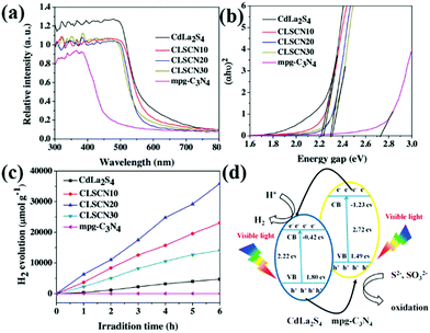 | ||
| Fig. 24 (a) UV-vis diffuse reflectance spectra of CdLa2S4/mesoporous graphitic carbon nitride (mpg-C3N4) composites; (b) band gaps estimated by the Kubelka–Munk function for the as-prepared samples; (c) plots of the photocatalytic H2 evolution amount vs. irradiation time for the as-synthesized samples; and (d) proposed photocatalytic H2 production and charge transfer mechanisms of CdLa2S4/mpg-C3N4 composites. Reprinted from ref. 208, Copyright (2016), with permission from Elsevier. | ||
3.2 Application in the photocatalytic reduction of carbon dioxide
With the development of economy and the intensification of human activities, CO2 in the atmosphere is increasing. The use of CO2 to convert solar energy into usable chemical energy has also been proposed. PCN also has great potential in photocatalytic CO2 reduction because of its suitable band position; the redox potential values of CO2/CO and CO2/CH4 are −0.53 and −0.24 V vs. NHE, pH 7, respectively.139,209–213 For example, Yang et al.139 developed a novel heterojunction (porous g-C3N nanosheets (PCNNS)/Sb-doped SnO2 nanoparticles (SSOP)) constructed from PCNNS and SSOP. A feasible mechanism for the CO2 photocatalytic reduction over the PCNNS/SSOP composite photocatalyst was proposed on the basis of the experimental results (Fig. 25). Under visible-light irradiation, PCNNS were excited to produce photogenerated electrons from the VB to its corresponding CB. Those photogenerated electrons in the CB of PCNNS could then transfer to the CB and the defect levels of SSOP because of their staggered band positions. This occurrence resulted in the effective separation of the photogenerated charges. The photogenerated electrons in the CB can reduce CO2 to CO and CH4 because of the CB location (−0.53 V vs. NHE, pH 7) of SSOP. The optimized PCNNS/SSOP composite photocatalyst exhibited an optimal CO2-reduction rate for CO evolution, which is 21.38 and 12.83 times higher than those of BCN and SSOP, respectively. The CO2-reduction rate for CH4 evolution of the optimized PCNNS/SSOP composite photocatalyst is 3.75-fold higher than that of SSOP.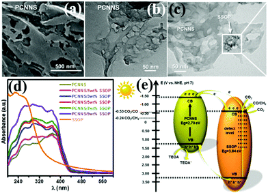 | ||
| Fig. 25 (a) SEM and (b) TEM images of the as-synthesized porous g-C3N4 nanosheet (PCNNS) samples; (c) TEM image of a PCNNS/5 wt% Sb doped SnO2 nanoparticle (SSOP) composite; (d) UV-vis diffuse reflectance spectra of the as-prepared pure PCNNS, PCNNS/SSOP composites with different SSOP contents (1, 3, 5, 7 and 9 wt%) and pure SSOP samples; and (e) schematic energy level diagrams of the pure PCNNS and pure SSOP samples, and the electron transfer dynamics involved in photocatalytic CO2 reduction. Reprinted from ref. 139, Copyright (2017), with permission from Elsevier. | ||
Recently, the CO2 increase has caused global warming to some extent. “Negative carbon economy” has attracted increasing attention because of the effects of global warming.214–216 Reducing the amount of CO2 in the atmosphere is becoming highly urgent. Huo et al.210 designed novel Z-scheme heterostructures between Pg-C3N4 nanosheets and Sn2S3-DETA nanorods for photocatalytic CO2 reduction (PCR). The experimental results exhibited that the Z-scheme heterostructure composite photocatalysts exhibited a higher PCR performance than pure Pg-C3N4 and Sn2S3-DETA. Fig. 26 shows that the optimized Pg-C3N4/Sn2S3-DETA composite photocatalysts displayed high CH4 and CH3OH production rates of 4.84 and 1.35 μmol h−1 g−1, respectively. The superior PCR performance should be ascribed to the formation of Z-scheme heterostructures between the Pg-C3N4 nanosheets and Sn2S3-DETA nanorods. This approach is useful for efficient separation of photogenerated electron–hole pairs. The porous structure of carbon nitride also provided many surface-active sites for photocatalytic reactions.
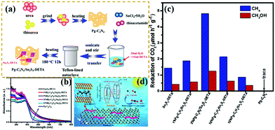 | ||
| Fig. 26 (a) Schematic illustration of the preparation process for porous g-C3N4 (Pg-C3N4)/Sn2S3-DETA; (b) UV-vis DRS spectra of the as-prepared samples; (c) comparison of the photocatalytic CO2 reduction (PCR) rates of different photocatalysts under visible light irradiation; and (d) schematic representation of a Pg-C3N4/Sn2S3-DETA system. Reprinted from ref. 210, Copyright (2018), with permission from Elsevier. | ||
The products of CO2 photocatalytic reduction will change with the change in PCN-based composite photocatalysts. The reduction products, such as CO, NH4, and CH3OH, can be obtained because of the different band positions of PCN-based composite photocatalysts. Although the PCN-based composite photocatalysts have different reduction products of CO2, they all exhibit excellent photocatalytic CO2 reduction activity. The problem caused by CO2 should be dealt with. In the future, CO2 may also become a new form of energy to solve the energy shortage problem.
3.3 Application in the photocatalytic degradation of pollutants
Photocatalytic degradation, an environment-friendly and efficiently advanced oxidation process, has attracted extensive attention.182,217–226 With the development of economy, environmental pollution has seriously damaged the ecological environment and threatened the health and safety of human beings. A green and efficient photocatalyst should be designed to degrade pollutants. For example, Li et al.227 successfully prepared hierarchical Pg-C3N4 foam (FCN) by using low-cost polyurethane sponge as a soft template. In comparison with traditional soft templates, the polyurethane sponge had no carbon residue nor reacted with precursors. Fig. 27 shows that the porous structure consisted of interconnected micron- (1–2 μm) and nano-scale (20–80 nm) pores. This feature is beneficial to increase the number of surface active sites and promote photogenic electron transfer. The experimental results show that the optimized FCN exhibited higher photocatalytic activity for phenol degradation (4 times) than traditional g-C3N4 because of the presence of a porous structure.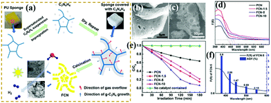 | ||
| Fig. 27 (a) Schematic for the preparation of porous g-C3N4 foam (FCN) materials; (b and c) SEM images of FCN-5 (where 5 represents the heating rate of polyurethane sponge (PU)); (d) UV-vis absorption spectra of the as-prepared samples; (e) photodegradation of phenol over pristine g-C3N4 (PCN) and FCN materials; and (f) AQY for FCN-5 under irradiation with different monochromatic lights. Reprinted from ref. 227, Copyright (2018), with permission from Elsevier. | ||
PCN can potentially solve environmental pollution and the energy crisis because of its excellent optical properties, chemical stability, and environmental friendliness. Therefore, paying attention to the research and development of PCN can lay a foundation for the early solution to these two problems.
4. Conclusion and outlook
In summary, PCN has always been a top research topic in recent years and will be a major one in the future because of its unique optical and chemical properties. Fig. 28 features the main development of PCN in recent years. In this review, we have first introduced two distinct methods to prepare PCN. The first one is a bottom-up approach that involves template and supramolecular self-assembly methods. The other one is a top-down approach, which includes chemical exfoliation and thermal oxidation. The preparation process and formation mechanism are described in detail. Thereafter, the fundamental properties of different morphologies and the functional modification of PCN are also summarized. The functional modification of PCN is emphasized, including heteroatom doping, introduction of surface defects, and heterojunction formation. Finally, the application of PCN-based photocatalysts is introduced in the field of photocatalysis, such as photocatalytic hydrogen production, photocatalytic pollutant degradation, and photocatalytic CO2 reduction.Despite the advances in PCN in recent years, some challenges still remain. In terms of preparation methods, the template method can be used to prepare relatively regular PCN. However, the application of the template method in preparing PCN is restricted by the use of a toxic remover in the hard template method and the release of harmful gas in the soft template method. Although supramolecular self-assembly can avoid toxic removers and harmful gases, the preparation of supramolecular precursors requires the use of organic reagents, which also inhibits the formation of hydrogen bonds in supramolecular precursors. Therefore, stable and easy to remove hard templates, green soft templates, and supramolecular precursors that can be synthesized in water solvents at room temperature should be determined in the future.
The morphological change can also improve the photocatalytic performance of PCN. For example, the PCN with a sheet structure can shorten the transmission path of photogenerated charge carriers. The PCN with a rod structure can effectively transfer photoinduced carriers along the 1D path. The PCN with a hollow sphere structure can reflect incident light many times to improve the light utilization rate. However, the change in morphology can only play an auxiliary role in the photocatalytic activity of PCN. Specifically, the increase of the photocatalytic activity of carbon nitride is obscured. Therefore, the morphological change can have a synergistic effect when combined with heteroatom doping or heterojunction formation to improve the PCN photocatalytic activity in the future.
In the functional modification of PCN, the introduction of surface defects and heteroatom doping can affect the electronic structure of PCN. However, surface defects are primarily reflected in the increase of surface active sites. In heteroatom doping, the effects of distinct doping atoms are different. Some defects affect the highest occupied molecular orbital (HOMO) of carbon nitride, such as S atoms.134 By contrast, other defects affect the lowest unoccupied molecular orbital (LUMO) of carbon nitride, such as P atoms.228 Other defects affect the HOMO and LUMO of carbon nitride, such as O atoms.214 Doping with metal elements is primarily reflected in the promotion of photogenerated electron transfer. This occurrence is similar to that in heterojunction formation. Heterojunctions enhance the photocatalytic activity to promote the separation of photogenerated carriers. Accordingly, the concentration of photogenerated electrons participating in the reaction is increased. Therefore, two-element or even three-element doping can be developed in the future to solve the shortcomings of carbon nitride in various aspects. Combining modified unitary PCN with other photocatalysts or co-catalysts will be a good means to form heterojunctions, which will further improve the photocatalytic activity. Theoretical calculation has great potential in explaining electronic band structures. However, few reports on the theoretical calculation of PCN are available. This situation may lead to the unclear principle of many modification methods for improving the photocatalytic activity. Therefore, future work can be inclined to explain the principle of modified carbon nitride.
Overall, this review summarizes the development of PCN, i.e., synthesis, morphology, modification, and application, in recent years. We believe that PCN can serve as a reference for the development of g-C3N4 and lay a foundation for the design of ideal photocatalysts in the future.
Conflicts of interest
There are no conflicts to declare.Acknowledgements
This work was partially supported by the National Natural Science Foundation of China under Grant No. 51672099 and 21403079, the Sichuan Science and Technology Program under No. 2019JDRC0027, and the Fundamental Research Funds for the Central Universities under No. 2017-QR-25.References
- M. Aleksandrzak, D. Baranowska, T. Kedzierski, K. Sielicki, S. Zhang, M. Biegun and E. Mijowska, Appl. Catal., B, 2019, 257, 117906 CrossRef CAS.
- D. K. Chauhan, S. Jain, V. R. Battula and K. Kailasam, Carbon, 2019, 152, 40–58 CrossRef CAS.
- C. Y. Feng, L. Tang, Y. C. Deng, G. M. Zeng, J. J. Wang, Y. N. Liu, Z. M. Chen, J. F. Yu and J. J. Wang, Appl. Catal., B, 2019, 256, 117827 CrossRef CAS.
- M. S. Nasir, G. R. Yang, I. Ayub, S. Wang, L. Wang, X. J. Wang, W. Yan, S. J. Peng and S. Ramakarishna, Appl. Catal., B, 2019, 257, 117855 CrossRef CAS.
- Y. Li, D. Zhang, X. Feng and Q. Xiang, Chin. J. Catal., 2020, 41, 21–30 CrossRef CAS.
- P. Yadav, S. T. Nishanthi, B. Purohit, A. Shanavas and K. Kailasam, Carbon, 2019, 152, 587–597 CrossRef CAS.
- J. N. Zhu, X. Q. Zhu, F. F. Cheng, P. Li, F. Wang, Y. W. Xiao and W. W. Xiong, Appl. Catal., B, 2019, 256, 117830 CrossRef CAS.
- L. L. Zhang, Z. Q. Wang, C. Hu and B. Y. Shi, Appl. Catal., B, 2019, 257, 117785 CrossRef CAS.
- M. H. Ai, J. W. Zhang, R. J. Gao, L. Pan, X. W. Zhang and J. J. Zou, Appl. Catal., B, 2019, 256, 117805 CrossRef CAS.
- F. Cheng, H. Yin and Q. Xiang, Appl. Surf. Sci., 2017, 391, 432–439 CrossRef CAS.
- Q. Liang, Z. Li, X. Yu, Z. H. Huang, F. Kang and Q. H. Yang, Adv. Mater., 2015, 27, 4634–4639 CrossRef CAS PubMed.
- Y. Li, X. Feng, Z. Lu, H. Yin, F. Liu and Q. Xiang, J. Colloid Interface Sci., 2018, 513, 866–876 CrossRef CAS PubMed.
- K. Qi, Y. Xie, R. Wang, S.-Y. Liu and Z. Zhao, Appl. Surf. Sci., 2019, 466, 847–853 CrossRef CAS.
- Q. Xiang, F. Li, D. Zhang, Y. Liao and H. Zhou, Appl. Surf. Sci., 2019, 495, 143520 CrossRef CAS.
- L. Yang, P. Wang, J. Yin, C. Wang, G. Dong, Y. Wang and W. Ho, Appl. Catal., B, 2019, 250, 42–51 CrossRef CAS.
- W. Iqbal, B. Qiu, Q. Zhu, M. Xing and J. Zhang, Appl. Catal., B, 2018, 232, 306–313 CrossRef CAS.
- K. Maeda, ACS Catal., 2013, 3, 1486–1503 CrossRef CAS.
- H. Kato, K. Asakura and A. Kudo, J. Am. Chem. Soc., 2003, 125, 3082–3089 CrossRef CAS PubMed.
- P. Qiu, C. Xu, H. Chen, F. Jiang, X. Wang, R. Lu and X. Zhang, Appl. Catal., B, 2017, 206, 319–327 CrossRef CAS.
- X. Miao, X. Yue, Z. Ji, X. Shen, H. Zhou, M. Liu, K. Xu, J. Zhu, G. Zhu, L. Kong and S. A. Shah, Appl. Catal., B, 2018, 227, 459–469 CrossRef CAS.
- P.-W. Chen, K. Li, Y.-X. Yu and W.-D. Zhang, Appl. Surf. Sci., 2017, 392, 608–615 CrossRef CAS.
- Y. Zhang, S. Zong, C. Cheng, J. Shi, X. Guan, Y. Lu and L. Guo, Int. J. Hydrogen Energy, 2018, 43, 13953–13961 CrossRef CAS.
- Y. Yang, D. Zhang and Q. Xiang, Nanoscale, 2019, 11, 18797–18805 RSC.
- M. Zhu, S. Kim, L. Mao, M. Fujitsuka, J. Zhang, X. Wang and T. Majima, J. Am. Chem. Soc., 2017, 139, 13234–13242 CrossRef CAS PubMed.
- J. Liu, Y. Liu, N. Liu, Y. Han, X. Zhang, H. Huang, Y. Lifshitz, S.-T. Lee, J. Zhong and Z. Kang, Science, 2015, 347, 970–974 CrossRef CAS PubMed.
- J. Fu, Q. Xu, J. Low, C. Jiang and J. Yu, Appl. Catal., B, 2019, 243, 556–565 CrossRef CAS.
- F. Chen, H. Yang, X. Wang and H. Yu, Chin. J. Catal., 2017, 38, 296–304 CrossRef CAS.
- K. He, J. Xie, M. Li and X. Li, Appl. Surf. Sci., 2018, 430, 208–217 CrossRef CAS.
- G. M. Ba, Z. W. Liang, H. P. Li, N. Du, J. Q. Liu and W. G. Hou, Appl. Catal., B, 2019, 253, 359–368 CrossRef CAS.
- M. J. Liu, S. Wageh, A. A. Al-Ghamdi, P. F. Xia, B. Cheng, L. Y. Zhang and J. G. Yu, Chem. Commun., 2019, 55, 14023–14026 RSC.
- M. Bellardita, E. I. Garcia-Lopez, G. Marci, I. Krivtsov, J. R. Garcia and L. Palmisano, Appl. Catal., B, 2018, 220, 222–233 CrossRef CAS.
- X. Liu, P. Wang, H. Zhai, Q. Zhang, B. Huang, Z. Wang, Y. Liu, Y. Dai, X. Qin and X. Zhang, Appl. Catal., B, 2018, 232, 521–530 CrossRef CAS.
- S. Zhang, J. Li, X. Wang, Y. Huang, M. Zeng and J. Xu, ACS Appl. Mater. Interfaces, 2014, 6, 22116–22125 CrossRef CAS PubMed.
- Z. Zhu, H. Pan, M. Murugananthan, J. Gong and Y. Zhang, Appl. Catal., B, 2018, 232, 19–25 CrossRef CAS.
- S. Zhang, C. Hu, H. Ji, L. Zhang and F. Li, Appl. Surf. Sci., 2019, 478, 304–312 CrossRef CAS.
- C. Dong, Z. Ma, R. Qie, X. Guo, C. Li, R. Wang, Y. Shi, B. Dai and X. Jia, Appl. Catal., B, 2017, 217, 629–636 CrossRef CAS.
- H. Li, L. Z. Wang, Y. D. Liu, J. Y. Lei and J. L. Zhang, Res. Chem. Intermed., 2016, 42, 3979–3998 CrossRef CAS.
- S. Sun and S. Liang, Nanoscale, 2017, 9, 10544–10578 RSC.
- Y. Wang, Q. Jiang, J. K. Shang, J. Xu and Y. X. Li, Acta Phys.-Chim. Sin., 2016, 32, 1913–1928 CAS.
- A. Mishra, A. Mehta, S. Basu, N. P. Shetti, K. R. Reddy and T. M. Aminabhavi, Carbon, 2019, 149, 693–721 CrossRef CAS.
- G. F. Liao, Y. Gong, L. Zhang, H. Y. Gao, G. J. Yang and B. Z. Fang, Energy Environ. Sci., 2019, 12, 2080–2147 RSC.
- T. Wang, C. Y. Nie, Z. M. Ao, S. B. Wang and T. C. An, J. Mater. Chem. A, 2020, 8, 485–502 RSC.
- N. Tian, H. W. Huang, X. Du, F. Dong and Y. H. Zhang, J. Mater. Chem. A, 2020, 8, 11584–11612 RSC.
- Q. Han, N. Chen, J. Zhang and L. T. Qu, Mater. Horiz., 2017, 4, 832–850 RSC.
- Y. Xiao, G. Tian, W. Li, Y. Xie, B. Jiang, C. Tian, D. Zhao and H. Fu, J. Am. Chem. Soc., 2019, 141, 2508–2515 CrossRef CAS PubMed.
- F. Guo, M. Li, H. Ren, X. Huang, K. Shu, W. Shi and C. Lu, Sep. Purif. Technol., 2019, 228, 115770 CrossRef CAS.
- M. Groenewolt and M. Antonietti, Adv. Mater., 2005, 17, 1789–1792 CrossRef CAS.
- M. Peer, M. Lusardi and K. F. Jensen, Chem. Mater., 2017, 29, 1496–1506 CrossRef CAS.
- Z. Zhao, Y. Dai, J. Lin and G. Wang, Chem. Mater., 2014, 26, 3151–3161 CrossRef CAS.
- S. Zhao, Y. Zhang, J. Fang, H. Zhang, Y. Wang, Y. Zhou, W. Chen and C. Zhang, ACS Sustainable Chem. Eng., 2018, 6, 8291–8299 CrossRef CAS.
- S. Obregón, A. Vázquez, M. A. Ruíz-Gómez and V. Rodríguez-González, Appl. Surf. Sci., 2019, 488, 205–212 CrossRef.
- X. H. Li, J. Zhang, X. Chen, A. Fischer, A. Thomas, M. Antonietti and X. Wang, Chem. Mater., 2011, 23, 4344–4348 CrossRef CAS.
- W. Xing, W. Tu, Z. Han, Y. Hu, Q. Meng and G. Chen, ACS Energy Lett., 2018, 3, 514–519 CrossRef CAS.
- S. Zhang, S. Song, P. C. Gu, R. Ma, D. L. Wei, G. X. Zhao, T. Wen, R. Jehan, B. W. Hu and X. K. Wang, J. Mater. Chem. A, 2019, 7, 5552–5560 RSC.
- H. Wei, W. A. McMaster, J. Z. Y. Tan, L. Cao, D. Chen and R. A. Caruso, J. Phys. Chem. C, 2017, 121, 22114–22122 CrossRef CAS.
- R. Hao, G. Wang, H. Tang, L. Sun, C. Xu and D. Han, Appl. Catal., B, 2016, 187, 47–58 CrossRef CAS.
- J. Wang, C. Zhang, Y. Shen, Z. Zhou, J. Yu, Y. Li, W. Wei, S. Liu and Y. Zhang, J. Mater. Chem. A, 2015, 3, 5126–5131 RSC.
- Y. Zheng, L. Lin, B. Wang and X. Wang, Angew. Chem., Int. Ed., 2015, 54, 12868–12884 CrossRef CAS PubMed.
- Y. Zhou, W. Lv, B. Zhu, F. Tong, J. Pan, J. Bai, Q. Zhou and H. Qin, ACS Sustainable Chem. Eng., 2019, 7, 5801–5807 CrossRef CAS.
- Y. Wang, X. Wang, M. Antonietti and Y. Zhang, ChemSusChem, 2010, 3, 435–439 CrossRef CAS PubMed.
- Q. Fan, J. Liu, Y. Yu and S. Zuo, RSC Adv., 2014, 4, 61877–61883 RSC.
- G. Arrachart, C. Carcel, P. Trens, J. J. E. Moreau and M. Wong Chi Man, Chem. – Eur. J., 2009, 15, 6279–6288 CrossRef CAS PubMed.
- T. Aida, E. W. Meijer and S. I. Stupp, Science, 2012, 335, 813–817 CrossRef CAS PubMed.
- M. Shalom, M. Guttentag, C. Fettkenhauer, S. Inal, D. Neher, A. Llobet and M. Antonietti, Chem. Mater., 2014, 26, 5812–5818 CrossRef CAS.
- M. Shalom, S. Inal, C. Fettkenhauer, D. Neher and M. Antonietti, J. Am. Chem. Soc., 2013, 135, 7118–7121 CrossRef CAS PubMed.
- Z. P. Chen, M. Antonietti and D. Dontsova, Chemistry, 2015, 21, 10805–10811 CrossRef CAS PubMed.
- E. E. Simanek, M. Mammen, D. M. Gordon, D. Chin, J. P. Mathias, C. T. Seto and G. M. Whitesides, Tetrahedron, 1995, 51, 607–619 CrossRef CAS.
- Y.-S. Jun, E. Z. Lee, X. Wang, W. H. Hong, G. D. Stucky and A. Thomas, Adv. Funct. Mater., 2013, 23, 3661–3667 CrossRef CAS.
- Y. Ishida, L. Chabanne, M. Antonietti and M. Shalom, Langmuir, 2014, 30, 447–451 CrossRef CAS PubMed.
- A. Ranganathan, V. R. Pedireddi and C. N. R. Rao, J. Am. Chem. Soc., 1999, 121, 1752–1753 CrossRef CAS.
- N. A. Wasio, R. C. Quardokus, R. P. Forrest, C. S. Lent, S. A. Corcelli, J. A. Christie, K. W. Henderson and S. A. Kandel, Nature, 2014, 507, 86–89 CrossRef CAS PubMed.
- G. M. Whitesides, J. P. Mathias and C. T. Seto, Science, 1991, 254, 1312–1319 CrossRef CAS PubMed.
- P. Yang, J. Zhao, W. Qiao, L. Li and Z. Zhu, Nanoscale, 2015, 7, 18887–18890 RSC.
- J. Li, B. Shen, Z. Hong, B. Lin, B. Gao and Y. Chen, Chem. Commun., 2012, 48, 12017–12019 RSC.
- H. J. Li, B. W. Sun, L. Sui, D. J. Qian and M. Chen, Phys. Chem. Chem. Phys., 2015, 17, 3309–3315 RSC.
- D. Tasis, N. Tagmatarchis, A. Bianco and M. Prato, Chem. Rev., 2006, 106, 1105–1136 CrossRef CAS PubMed.
- J. Zhang, H. L. Zou, Q. Qing, Y. L. Yang, Q. W. Li, Z. F. Liu, X. Y. Guo and Z. L. Du, J. Phys. Chem. B, 2003, 107, 3712–3718 CrossRef CAS.
- L. Shi, K. Chang, H. Zhang, X. Hai, L. Yang, T. Wang and J. Ye, Small, 2016, 12, 4431–4439 CrossRef CAS PubMed.
- X. H. Chen, J. T. Xia, J. C. Peng, W. Z. Li and S. S. Xie, Compos. Sci. Technol., 2000, 60, 301–306 CrossRef CAS.
- H. Hiura, T. W. Ebbesen and K. Tanigaki, Adv. Mater., 1995, 7, 275–276 CrossRef CAS.
- X. Zhang, H. Wang, H. Wang, Q. Zhang, J. Xie, Y. Tian, J. Wang and Y. Xie, Adv. Mater., 2014, 26, 4438–4443 CrossRef CAS PubMed.
- Y. Xu, M. Xie, S. Huang, H. Xu, H. Ji, J. Xia, Y. Li and H. Li, RSC Adv., 2015, 5, 26281–26290 RSC.
- P. Niu, L. Zhang, G. Liu and H.-M. Cheng, Adv. Funct. Mater., 2012, 22, 4763–4770 CrossRef CAS.
- J. Zhang, Y. Chen and X. Wang, Energy Environ. Sci., 2015, 8, 3092–3108 RSC.
- X. Li, G. Hartley, A. J. Ward, P. A. Young, A. F. Masters and T. Maschmeyer, J. Phys. Chem. C, 2015, 119, 14938–14946 CrossRef CAS.
- P. Hu, C. Chen, R. Zeng, J. Xiang, Y. Huang, D. Hou, Q. Li and Y. Huang, Nano Energy, 2018, 50, 376–382 CrossRef CAS.
- X. She, L. Liu, H. Ji, Z. Mo, Y. Li, L. Huang, D. Du, H. Xu and H. Li, Appl. Catal., B, 2016, 187, 144–153 CrossRef CAS.
- W. Chen, S.-C. Wu, Z.-J. Xia, G.-B. Huang and J. Hu, J. Alloys Compd., 2019, 809, 151859 CrossRef CAS.
- C. Wang, T. Wu, X. Wang, Q. Wei, Y. Wang, C. Li and D. Sun, Sens. Actuators, B, 2019, 297, 126716 CrossRef CAS.
- B. Shao, X. Liu, Z. Liu, G. Zeng, W. Zhang, Q. Liang, Y. Liu, Q. He, X. Yuan, D. Wang, S. Luo and S. Gong, Chem. Eng. J., 2019, 374, 479–493 CrossRef.
- W. Luo, X. Chen, Z. Wei, D. Liu, W. Yao and Y. Zhu, Appl. Catal., B, 2019, 255, 117761 CrossRef CAS.
- B.-X. Zhou, S.-S. Ding, B.-J. Zhang, L. Xu, R.-S. Chen, L. Luo, W.-Q. Huang, Z. Xie, A. Pan and G.-F. Huang, Appl. Catal., B, 2019, 254, 321–328 CrossRef CAS.
- K. Hu, Z. Wei, Z. Yang, G. Jia, J. Dong, L. Zhu, X. Fan and M. Yao, Chem. Phys. Lett., 2019, 732, 136613 CrossRef CAS.
- Z. X. Zeng, K. X. Li, L. S. Yan, Y. H. Dai, H. Q. Guo, M. X. Huo and Y. H. Guo, RSC Adv., 2014, 4, 59513–59518 RSC.
- K. Li, X. Xie and W. D. Zhang, ChemCatChem, 2016, 8, 2128–2135 CrossRef CAS.
- S. Guo, Z. Deng, M. Li, B. Jiang, C. Tian, Q. Pan and H. Fu, Angew. Chem., Int. Ed., 2016, 55, 1830–1834 CrossRef CAS PubMed.
- Z. Mo, H. Xu, Z. Chen, X. She, Y. Song, J. Wu, P. Yan, L. Xu, Y. Leia, S. Yuan and H. Li, Appl. Catal., B, 2018, 225, 154–161 CrossRef CAS.
- M. Wu, J. Zhang, B.-B. He, H.-W. Wang, R. Wang and Y.-S. Gong, Appl. Catal., B, 2019, 241, 159–166 CrossRef CAS.
- Y. Zhang, J. Di, P. Ding, J. Zhao, K. Gu, X. Chen, C. Yan, S. Yin, J. Xia and H. Li, J. Colloid Interface Sci., 2019, 553, 530–539 CrossRef CAS PubMed.
- F. Ding, P. Chen, F. Liu, L. Chen, J.-K. Guo, S. Shen, Q. Zhang, L.-H. Meng, C.-T. Au and S.-F. Yin, Appl. Surf. Sci., 2019, 490, 102–108 CrossRef CAS.
- X.-C. Yang, Y.-L. Yang, S.-L. Zhang, Y.-F. Liu, S.-J. Fu, M. Zhu, J.-F. Hu, Z.-J. Zhang and J.-T. Zhao, Appl. Surf. Sci., 2019, 490, 592–597 CrossRef CAS.
- W. Xue, D. Huang, J. Li, G. Zeng, R. Deng, Y. Yang, S. Chen, Z. Li, X. Gong and B. Li, Chem. Eng. J., 2019, 373, 1144–1157 CrossRef CAS.
- N. Tian, K. Xiao, Y. Zhang, X. Lu, L. Ye, P. Gao, T. Ma and H. Huang, Appl. Catal., B, 2019, 253, 196–205 CrossRef CAS.
- T. Y. Ma, Y. Tang, S. Dai and S. Z. Qiao, Small, 2014, 10, 2382–2389 CrossRef CAS.
- S. Yang, Y. Gong, J. Zhang, L. Zhan, L. Ma, Z. Fang, R. Vajtai, X. Wang and P. M. Ajayan, Adv. Mater., 2013, 25, 2452–2456 CrossRef CAS PubMed.
- Q. Liu, X. Wang, Q. Yang, Z. Zhang and X. Fang, Appl. Surf. Sci., 2018, 450, 46–56 CrossRef CAS.
- M. Xiao, Z. Wang, M. Lyu, B. Luo, S. Wang, G. Liu, H.-M. Cheng and L. Wang, Adv. Mater., 2018, 31, 1801369 CrossRef PubMed.
- T. Su, Q. Shao, Z. Qin, Z. Guo and Z. Wu, ACS Catal., 2018, 8, 2253–2276 CrossRef CAS.
- P. Yang, H. Ou, Y. Fang and X. Wang, Angew. Chem., Int. Ed., 2017, 56, 3992–3996 CrossRef CAS PubMed.
- S. Zhao, Y. Zhang, Y. Zhou, Y. Wang, K. Qiu, C. Zhang, J. Fang and X. Sheng, Carbon, 2018, 126, 247–256 CrossRef CAS.
- Y. Si, Z. Sun, L. Huang, M. Chen and L. Wu, J. Mater. Chem. A, 2019, 7, 8952–8959 RSC.
- Z. Mo, X. Zhu, Z. Jiang, Y. Song, D. Liu, H. Li, X. Yang, Y. She, Y. Lei, S. Yuan, H. Li, L. Song, Q. Yan and H. Xu, Appl. Catal., B, 2019, 256, 117854 CrossRef CAS.
- Y. Huang, D. Li, Z. Fang, R. Chen, B. Luo and W. Shi, Appl. Catal., B, 2019, 254, 128–134 CrossRef CAS.
- J. Huang, Y. Cao, H. Wang, H. Yu, F. Peng, H. Zou and Z. Liu, Chem. Eng. J., 2019, 373, 687–699 CrossRef CAS.
- J. Tang, Y. Liu, Y. Hu, J. Huang, B. Wang, C. Yang and G. Yang, J. Power Sources, 2019, 434, 226731 CrossRef CAS.
- D. Ruan, S. Kim, M. Fujitsuka and T. Majima, Appl. Catal., B, 2018, 238, 638–646 CrossRef CAS.
- J. Liu, W. Li, L. Duan, X. Li, L. Ji, Z. Geng, K. Huang, L. Lu, L. Zhou, Z. Liu, W. Chen, L. Liu, S. Feng and Y. Zhang, Nano Lett., 2015, 15, 5137–5142 CrossRef CAS PubMed.
- K. Wang, Q. Li, B. Liu, B. Cheng, W. Ho and J. Yu, Appl. Catal., B, 2015, 176, 44–52 Search PubMed.
- N. Sagara, S. Kamimura, T. Tsubota and T. Ohno, Appl. Catal., B, 2016, 192, 193–198 CrossRef CAS.
- Y. Zhang, T. Mori, J. Ye and M. Antonietti, J. Am. Chem. Soc., 2010, 132, 6294–6295 CrossRef CAS PubMed.
- J. Ran, T. Y. Ma, G. Gao, X.-W. Du and S. Z. Qiao, Energy Environ. Sci., 2015, 8, 3708–3717 RSC.
- G. Zhang, M. Zhang, X. Ye, X. Qiu, S. Lin and X. Wang, Adv. Mater., 2014, 26, 805–809 CrossRef CAS PubMed.
- Q. Han, C. Hu, F. Zhao, Z. Zhang, N. Chen and L. Qu, J. Mater. Chem. A, 2015, 3, 4612–4619 RSC.
- D. Zhang, X. Ma, H. Zhang, Y. Liao and Q. Xiang, Mater. Today Energy, 2018, 10, 132–140 CrossRef.
- H. Tang, R. Wang, C. Zhao, Z. Chen, X. Yang, D. Bukhvalov, Z. Lin and Q. Liu, Chem. Eng. J., 2019, 374, 1064–1075 CrossRef CAS.
- X. Wu, F. Chen, X. Wang and H. Yu, Appl. Surf. Sci., 2018, 427, 645–653 CrossRef CAS.
- Z.-F. Huang, J. Song, L. Pan, Z. Wang, X. Zhang, J.-J. Zou, W. Mi, X. Zhang and L. Wang, Nano Energy, 2015, 12, 646–656 CrossRef CAS.
- S. Wang, F. He, X. Zhao, J. Zhang, Z. Ao, H. Wu, Y. Yin, L. Shi, X. Xu, C. Zhao, S. Wang and H. Sun, Appl. Catal., B, 2019, 257, 117931 CrossRef CAS.
- T. Zeng, S. Li, Y. Shen, H. Zhang, H. Feng, X. Zhang, L. Li, Z. Cai and S. Song, Appl. Catal., B, 2019, 257, 117915 CrossRef CAS.
- Z. Chen, T.-T. Fan, X. Yu, Q.-L. Wu, Q.-H. Zhu, L.-Z. Zhang, J.-H. Li, W.-P. Fang and X.-D. Yi, J. Mater. Chem. A, 2018, 6, 15310–15319 RSC.
- M. Jourshabani, Z. Shariatinia and A. Badiei, Langmuir, 2017, 33, 7062–7078 CrossRef CAS PubMed.
- K. Wu, D. Chen, J. Fang, S. Wu, F. Yang, X. Zhu and Z. Fang, Appl. Surf. Sci., 2018, 462, 991–1001 CrossRef CAS.
- F. Yang, J. Ren, Q. Liu, L. Zhang, Y. Chai and W.-L. Dai, J. Energy Chem., 2019, 33, 1–8 CrossRef.
- F. Raziq, M. Humayun, A. Ali, T. Wang, A. Khan, Q. Fu, W. Luo, H. Zeng, Z. Zheng, B. Khan, H. Shen, X. Zu, S. Li and L. Qiao, Appl. Catal., B, 2018, 237, 1082–1090 CrossRef CAS.
- J.-W. Zhang, S. Gong, N. Mahmood, L. Pan, X. Zhang and J.-J. Zou, Appl. Catal., B, 2018, 221, 9–16 CrossRef CAS.
- W. Chen, T. Y. Liu, T. Huang, X. H. Liu and X. J. Yang, Nanoscale, 2016, 8, 3711–3719 RSC.
- S. Le, T. Jiang, Q. Zhao, X. Liu, Y. Li, B. Fang and M. Gong, RSC Adv., 2016, 6, 38811–38819 RSC.
- J. C. Wang, C. X. Cui, Y. Li, L. Liu, Y. P. Zhang and W. Shi, J. Hazard. Mater., 2017, 339, 43–53 CrossRef CAS PubMed.
- L. Yang, J. Huang, L. Shi, L. Cao, H. Liu, Y. Liu, Y. Li, H. Song, Y. Jie and J. Ye, Appl. Catal., B, 2018, 221, 670–680 CrossRef CAS.
- S. Hu, Y. Zhou, M. He, Q. Liao, H. Yang, H. Li, R. Xu and Q. Ding, Mater. Lett., 2018, 231, 171–174 CrossRef CAS.
- Z. Wang, M. Chen, Y. Huang, X. Shi, Y. Zhang, T. Huang, J. Cao, W. Ho and S. C. Lee, Appl. Catal., B, 2018, 239, 352–361 CrossRef CAS.
- L. Yang, J. Huang, L. Shi, L. Cao, Q. Yu, Y. Jie, J. Fei, H. Ouyang and J. Ye, Appl. Catal., B, 2017, 204, 335–345 CrossRef CAS.
- L. Ming, H. Yue, L. Xu and F. Chen, J. Mater. Chem. A, 2014, 2, 19145–19149 RSC.
- J. Li, B. Shen, Z. Hong, B. Lin, B. Gao and Y. Chen, Chem. Commun., 2012, 48, 12017–12019 RSC.
- S. Liu, D. Li, H. Sun, H. M. Ang, M. O. Tade and S. Wang, J. Colloid Interface Sci., 2016, 468, 176–182 CrossRef CAS PubMed.
- Y. Wang, X. Wang and M. Antonietti, Angew. Chem., Int. Ed., 2012, 51, 68–89 CrossRef CAS PubMed.
- Y. Deng, L. Tang, G. Zeng, Z. Zhu, M. Yan, Y. Zhou, J. Wang, Y. Liu and J. Wang, Appl. Catal., B, 2017, 203, 343–354 CrossRef CAS.
- Z. Li, C. Kong and G. Lu, J. Phys. Chem. C, 2016, 120, 56–63 CrossRef CAS.
- D. Ghosh, G. Periyasamy, B. Pandey and S. K. Pati, J. Mater. Chem. C, 2014, 2, 7943–7951 RSC.
- S. Hu, F. Li, Z. Fan, F. Wang, Y. Zhao and Z. Lv, Dalton Trans., 2015, 44, 1084–1092 RSC.
- M. Wu, J.-M. Yan, X.-N. Tang, M. Zhao and Q. Jiang, ChemSusChem, 2014, 7, 2654–2658 CrossRef CAS PubMed.
- B. Yue, Q. Li, H. Iwai, T. Kako and J. Ye, Sci. Technol. Adv. Mater., 2011, 12, 034401 CrossRef PubMed.
- J. Chen, Z. Hong, Y. Chen, B. Lin and B. Gao, Mater. Lett., 2015, 145, 129–132 CrossRef CAS.
- Y. R. Guo, Q. Liu, Z. H. Li, Z. G. Zhang and X. M. Fang, Appl. Catal., B, 2018, 221, 362–370 CrossRef CAS.
- W. Wu, Z. Ruan, J. Li, Y. Li, Y. Jiang, X. Xu, D. Li, Y. Yuan and K. Lin, Nano-Micro Lett., 2019, 11, 10 CrossRef CAS.
- F. Li, P. Zhu, S. Wang, X. Xu, Z. Zhou and C. Wu, RSC Adv., 2019, 9, 20633–20642 RSC.
- X. Ma, Q. Xiang, Y. Liao, T. Wen and H. Zhang, Appl. Surf. Sci., 2018, 457, 846–855 CrossRef CAS.
- L. Cheng, D. Zhang, Y. Liao, F. Li, H. Zhang and Q. Xiang, J. Colloid Interface Sci., 2019, 555, 94–103 CrossRef CAS PubMed.
- R. Shen, C. Jiang, Q. Xiang, J. Xie and X. Li, Appl. Surf. Sci., 2019, 471, 43–87 CrossRef CAS.
- R. Shen, J. Xie, Q. Xiang, X. Chen, J. Jiang and X. Li, Chin. J. Catal., 2019, 40, 240–288 CrossRef CAS.
- Y. Xia, Q. Li, K. Lv and M. Li, Appl. Surf. Sci., 2017, 398, 81–88 CrossRef CAS.
- Q. Xiang, F. Cheng and D. Lang, ChemSusChem, 2016, 9, 996–1002 CrossRef CAS PubMed.
- B. Wu, Y. Li, K. Su, L. Tan, X. Liu, Z. Cui, X. Yang, Y. Liang, Z. Li, S. Zhu, K. W. K. Yeung and S. Wu, J. Hazard. Mater., 2019, 377, 227–236 CrossRef CAS PubMed.
- X. Lu, J. Xie, X. Chen and X. Li, Appl. Catal., B, 2019, 252, 250–259 CrossRef CAS.
- C. Han, T. Zhang, Q. Cai, C. Ma, Z. Tong and Z. Liu, J. Am. Chem. Soc., 2019, 102, 5484–5493 CAS.
- S. Zhang, P. Gu, R. Ma, C. Luo, T. Wen, G. Zhao, W. Cheng and X. Wang, Catal. Today, 2019, 335, 65–77 CrossRef CAS.
- Y. Liu, X. Zeng, X. Hu, J. Hu, Z. Wang, Y. Yin, C. Sun and X. Zhang, Catal. Today, 2019, 335, 243–251 CrossRef CAS.
- Y. J. Ren, D. Q. Zeng and W. J. Ong, Chin. J. Catal., 2019, 40, 289–319 CrossRef CAS.
- N. Xiao, S. S. Li, S. Liu, B. R. Xu, Y. D. Li, Y. Q. Gao, L. Ge and G. W. Lu, Chin. J. Catal., 2019, 40, 289–319 CrossRef.
- Z. Dong, J. Pan, B. Wang, Z. Jiang, C. Zhao, J. Wang, C. Song, Y. Zheng, C. Cui and C. Li, J. Alloys Compd., 2018, 747, 788–795 CrossRef CAS.
- D. Jiang, L. Chen, J. Zhu, M. Chen, W. Shi and J. Xie, Dalton Trans., 2013, 42, 15726–15734 RSC.
- Y.-N. Li, Z.-Y. Chen, M.-Q. Wang, L.-z. Zhang and S.-J. Bao, Appl. Surf. Sci., 2018, 440, 229–236 CrossRef CAS.
- X.-j. Wang, W.-y. Yang, F.-t. Li, Y.-b. Xue, R.-h. Liu and Y.-j. Hao, Ind. Eng. Chem. Res., 2013, 52, 17140–17150 CrossRef CAS.
- F. Ning, M. Shao, C. Zhang, S. Xu, M. Wei and X. Duan, Nano Energy, 2014, 7, 134–142 CrossRef CAS.
- X. Lu, Q. Wang and D. Cui, J. Mater. Sci. Technol., 2010, 26, 925–930 CrossRef CAS.
- Q. Liang, J. Jin, M. Zhang, C. Liu, S. Xu, C. Yao and Z. Li, Appl. Catal., B, 2017, 218, 545–554 CrossRef CAS.
- T. Kanagaraj, S. Thiripuranthagan, S. M. K. Paskalis and H. Abe, Appl. Surf. Sci., 2017, 426, 1030–1045 CrossRef CAS.
- J. Zhang, J. Fu, Z. Wang, B. Cheng, K. Dai and W. Ho, J. Alloys Compd., 2018, 766, 841–850 CrossRef CAS.
- W. Guo, K. Fan, J. Zhang and C. Xu, Appl. Surf. Sci., 2018, 447, 125–134 CrossRef CAS.
- Z. Wang, J. Lv, J. Zhang, K. Dai and C. Liang, Appl. Surf. Sci., 2018, 430, 595–602 CrossRef CAS.
- J. Zhang, J. Lv, K. Dai, Q. Liu, C. Liang and G. Zhu, Ceram. Int., 2017, 43, 1522–1529 CrossRef CAS.
- Y. Shang, X. Chen, W. Liu, P. Tan, H. Chen, L. Wu, C. Ma, X. Xiong and J. Pan, Appl. Catal., B, 2017, 204, 78–88 CrossRef CAS.
- Y. Huo, Y. Yang, K. Dai and J. Zhang, Appl. Surf. Sci., 2019, 481, 1260–1269 CrossRef CAS.
- Q. Xiang, X. Ma, D. Zhang, H. Zhou, Y. Liao, H. Zhang, S. Xu, I. Levchenko and K. Bazaka, J. Colloid Interface Sci., 2019, 556, 376–385 CrossRef CAS PubMed.
- X. Wu, J. Cheng, X. Li, Y. Li and K. Lv, Appl. Surf. Sci., 2019, 465, 1037–1046 CrossRef CAS.
- Q. Xiang, D. Lang, T. Shen and F. Liu, Appl. Catal., B, 2015, 162, 196–203 CrossRef CAS.
- L. Cheng, D. Zhang, Y. Liao, H. Zhang and Q. Xiang, Sol. RRL, 2019, 3, 1900062 CrossRef.
- K. He, J. Xie, Z.-Q. Liu, N. Li, X. Chen, J. Hu and X. Li, J. Mater. Chem. A, 2018, 6, 13110–13122 RSC.
- D. Lang, T. Shen and Q. Xiang, ChemCatChem, 2015, 7, 943–951 CrossRef CAS.
- W. Liu, J. Shen, Q. Liu, X. Yang and H. Tang, Appl. Surf. Sci., 2018, 462, 822–830 CrossRef CAS.
- L. Cheng, X. Li, H. Zhang and Q. Xiang, J. Phys. Chem. Lett., 2019, 10, 3488–3494 CrossRef CAS PubMed.
- X. Liu, F. Pang, M. He and J. Ge, Nano Res., 2017, 10, 3638–3647 CrossRef CAS.
- F. He, G. Chen, Y. Yu, Y. Zhou, Y. Zheng and S. Hao, Chem. Commun., 2015, 51, 425–427 RSC.
- X. She, L. Liu, H. Ji, Z. Mo, Y. Li, L. Huang, D. Du, H. Xu and H. Li, Appl. Catal., B, 2016, 187, 144–153 CrossRef CAS.
- K. Maeda, R. Kuriki, M. Zhang, X. Wang and O. Ishitani, J. Mater. Chem. A, 2014, 2, 15146–15151 RSC.
- W. Liu, J. Shen, X. Yang, Q. Liu and H. Tang, Appl. Surf. Sci., 2018, 456, 369–378 CrossRef CAS.
- Q. L. Xu, B. C. Zhu, B. Cheng, J. G. Yu, M. H. Zhou and W. K. Ho, Appl. Catal., B, 2019, 225, 117770 CrossRef.
- P. F. Xia, M. J. Liu, B. Cheng, J. G. Yu and L. Y. Zhang, ACS Sustainable Chem. Eng., 2018, 6, 8945–8953 CrossRef CAS.
- Q. L. Xu, B. Cheng, J. G. Yu and G. Liu, Carbon, 2017, 118, 241–249 CrossRef CAS.
- J. Bai, C. Yin, H. Xu, G. Chen, Z. Ni, Z. Wang, Y. Li, S. Kang, Z. Zheng and X. Li, J. Colloid Interface Sci., 2018, 532, 280–286 CrossRef CAS PubMed.
- W. Wang, Z. Shu, J. Zhou, T. Li, P. Duan, Z. Zhao, Y. Tan, C. Xie and S. Cui, Appl. Clay Sci., 2018, 158, 143–149 CrossRef CAS.
- D. Zhang, L. Liu, S. Xu, S. Du, W. Dong and J. Gong, J. Cryst. Growth, 2018, 486, 1–9 CrossRef CAS.
- N. Sun, Y. Liang, X. Ma and F. Chen, Chem. – Eur. J., 2017, 23, 15466–15473 CrossRef CAS PubMed.
- H. Yu, R. Shi, Y. Zhao, T. Bian, Y. Zhao, C. Zhou, G. I. N. Waterhouse, L.-Z. Wu, C.-H. Tung and T. Zhang, Adv. Mater., 2017, 29, 1605148 CrossRef PubMed.
- H. Yu, L. Shang, T. Bian, R. Shi, G. I. N. Waterhouse, Y. Zhao, C. Zhou, L.-Z. Wu, C.-H. Tung and T. Zhang, Adv. Mater., 2016, 28, 5080–5086 CrossRef CAS PubMed.
- G. Dong, K. Zhao and L. Zhang, Chem. Commun., 2012, 48, 6178–6180 RSC.
- H. Yang, Y. Zhou, Y. Wang, S. Hu, B. Wang, Q. Liao, H. Li, J. Bao, G. Ge and S. Jia, J. Mater. Chem. A, 2018, 6, 16485–16494 RSC.
- H. Liu, Z. Xu, Z. Zhang and D. Ao, Appl. Catal., B, 2016, 192, 234–241 CrossRef CAS.
- S. Guo, H. Zhang, P. Yang, Y. Chen, X. Yu, B. Yu, Y. Zhao, Z. Yang and Z. Liu, Catal. Sci. Technol., 2019, 9, 2485–2492 RSC.
- Y. Huo, J. Zhang, K. Dai, Q. Li, J. Lv, G. Zhu and C. Liang, Appl. Catal., B, 2019, 241, 528–538 CrossRef CAS.
- Y. Wang, Q. Xia, X. Bai, Z. Ge, Q. Yang, C. Yin, S. Kang, M. Dong and X. Li, Appl. Catal., B, 2018, 239, 196–203 CrossRef CAS.
- Q. Xiang, B. Cheng and J. Yu, Angew. Chem., Int. Ed., 2015, 54, 11350–11366 CrossRef CAS PubMed.
- L. Cheng, Q. Xiang, Y. Liao and H. Zhang, Energy Environ. Sci., 2018, 11, 1362–1391 RSC.
- M.-H. Sun, S.-Z. Huang, L.-H. Chen, Y. Li, X.-Y. Yang, Z.-Y. Yuan and B.-L. Su, Chem. Soc. Rev., 2016, 45, 3479–3563 RSC.
- T. Nakajima, Y. Tamaki, K. Ueno, E. Kato, T. Nishikawa, K. Ohkubo, Y. Yamazaki, T. Morimoto and O. Ishitani, J. Am. Chem. Soc., 2016, 138, 13818–13821 CrossRef CAS PubMed.
- J. Low, J. Yu, M. Jaroniec, S. Wageh and A. A. Al-Ghamdi, Adv. Mater., 2017, 29, 1601694 CrossRef PubMed.
- Z. Ma, C. Zeng, L. Hu, Q. Zhao, Q. Yang, J. Niu, B. Yao and Y. He, Appl. Surf. Sci., 2019, 484, 489–500 CrossRef CAS.
- L. Shi, F. Wang, L. Liang, K. Chen, M. Liu, R. Zhu and J. Sun, Catal. Commun., 2017, 89, 129–132 CrossRef CAS.
- X. Song, Q. Yang, X. Jiang, M. Yin and L. Zhou, Appl. Catal., B, 2017, 217, 322–330 CrossRef CAS.
- H. Wang, M. Li, H. Li, Q. Lu, Y. Zhang and S. Yao, Mater. Des., 2019, 162, 210–218 CrossRef CAS.
- J. Xiao, Y. Xie, F. Nawaz, Y. Wang, P. Du and H. Cao, Appl. Catal., B, 2016, 183, 417–425 CrossRef CAS.
- J. Xu, Z. Wang and Y. Zhu, ACS Appl. Mater. Interfaces, 2017, 9, 27727–27735 CrossRef CAS PubMed.
- Y. Yang, C. Zhang, D. Huang, G. Zeng, J. Huang, C. Lai, C. Zhou, W. Wang, H. Guo, W. Xue, R. Deng, M. Cheng and W. Xiong, Appl. Catal., B, 2019, 245, 87–99 CrossRef CAS.
- Y. Zeng, X. Liu, C. Liu, L. Wang, Y. Xia, S. Zhang, S. Luo and Y. Pei, Appl. Catal., B, 2018, 224, 1–9 CrossRef CAS.
- Y. Zhou, J. Li, C. Liu, P. Huo and H. Wang, Appl. Surf. Sci., 2018, 458, 586–596 CrossRef CAS.
- A. Zhu, L. Qiao, Z. Jia, P. Tan, Y. Liu, Y. Ma and J. Pan, Dalton Trans., 2017, 46, 17032–17040 RSC.
- Y. Li, Z. Ruan, Y. He, J. Li, K. Li, Y. Jiang, X. Xu, Y. Yuan and K. Lin, Appl. Catal., B, 2018, 236, 64–75 CrossRef CAS.
- F. Hu, W. Luo, Y. Hu, H. Dai and X. Peng, J. Alloys Compd., 2019, 794, 594–605 CrossRef CAS.
| This journal is © The Royal Society of Chemistry 2020 |

