 Open Access Article
Tetraarylborate polymer networks as single-ion conducting solid electrolytes†
Jeffrey F.
Van Humbeck
a,
Michael L.
Aubrey
b,
Alaaeddin
Alsbaiee
c,
Rob
Ameloot
 d,
Geoffrey W.
Coates
c,
William R.
Dichtel
c and
Jeffrey R.
Long
*be
aDepartment of Chemistry, Massachusetts Institute of Technology, 77 Massachusetts Avenue, Cambridge, Massachusetts, USA 02139
bDepartment of Chemistry, University of California, Berkeley, California, USA 94720-1462. E-mail: jrlong@berkeley.edu; Tel: +1 5106420860
cDepartment of Chemistry and Chemical Biology, Baker Laboratory, Cornell University, Ithaca, New York, USA 14853-1301
dCentre for Surface Chemistry and Catalysis, University of Leuven, Kasteelpark Arenberg 23, 3001 Leuven, Belgium
eDivision of Materials Sciences, Lawrence Berkeley National Laboratory, Berkeley, California, USA 94720
First published on 23rd June 2015
Abstract
A new family of solid polymer electrolytes based upon anionic tetrakis(phenyl)borate tetrahedral nodes and linear bis-alkyne linkers is reported. Sonogashira polymerizations using tetrakis(4-iodophenyl)borate, tetrakis(4-iodo-2,3,5,6-tetrafluorophenyl)borate and tetrakis(4-bromo-2,3,5,6-tetrafluorophenyl)borate delivered highly cross-linked polymer networks with both 1,4-diethynylbeznene and a tri(ethylene glycol) substituted derivative. Promising initial conductivity metrics have been observed, including high room temperature conductivities (up to 2.7 × 10⁻⁴ S cm−1), moderate activation energies (0.25–0.28 eV), and high lithium ion transport numbers (up to tLi+ = 0.93). Initial investigations into the effects of important materials parameters such as bulk morphology, porosity, fluorination, and other chemical modification, provide starting design parameters for further development of this new class of solid electrolytes.
Introduction
Emerging battery technologies using lithium metal or high-energy alloys at the anode promise cells with unprecedented energy densities.1 Their successful development will allow more power to be generated from renewable but intermittent sources.2 The redesign of many current cell components that are incompatible with these materials constitutes a major challenge for current research,3 and includes identifying replacements for the electrolytes now used in lithium-ion intercalation cells.4 Commercial devices rely on organic electrolyte solutions with lithium salts of simple non-coordinating anions (e.g. LiPF6) dissolved in highly polar and coordinating solvents, such as organic carbonates.4 These solutions present numerous safety and performance concerns.5 The lack of mechanical resistance in the electrolyte leads to device short circuits from lithium dendrite growth upon repeated charge/discharge cycles.6 Additionally, mobile counteranions in solution polarize the electrolyte, which decreases the operating voltage of the cell, potentially detracting from its lifetime and capacity as anions that have migrated to the anode decompose into insoluble materials such as LiF.7Several strategies are now being pursued to address these limitations. Anchoring the counteranions into a polymeric structure renders them immobile, providing so-called ‘single-ion’ conducting electrolytes.8 In theory, this approach prevents depletion of anions near the anode while charging. Such depletion produces a substantial electric field, which has been predicted to increase the rate of lithium dendrite formation.9 It has also been suggested that a mechanically resistant solid electrolyte with sufficient shear modulus (G′ > 7 GPa) could prevent lithium dendrites from crossing the cell and contacting the cathode.10 Indeed, a particular block copolymer (PS-b-PEO) that used a rigid polystyrene block to reinforce the conductive poly(ethylene oxide) fraction displayed improved resistance to dendrite penetration,11a although low modulus cross-linked PE-PEO materials also exhibited excellent dendrite growth resistance.11b Solid electrolytes that apply both strategies might provide excellent protection against both dendrite growth and cell failure from mechanical trauma.12
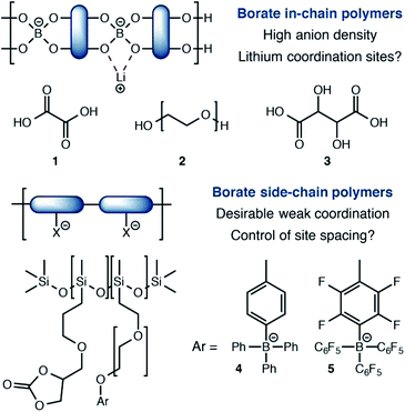
Among single-ion conducting electrolytes based upon organic polymers, anionic tetracoordinate borate centers have been studied in a number of contexts (Fig. 1). For example, borates are often incorporated into linear polymers, condensed from multifunctional alcohols13 and/or carboxylic acids.14 Capping or plasticizing agents such as oxalic acid (1) or polyethylene glycols (2) further modify their performance. A noteworthy and exceptionally anion-dense material utilized tartaric acid (3) as the boron-coordinating component.15 Although these approaches yield high anion densities, they also present stable coordination sites for lithium, which favor tight ion pairing that slows Li+ conduction. The recent work of Colby16 reports borate centers that do not interact with lithium strongly. Calculations suggested that siloxane polymers bearing tetraarylborate substituents (4) or their perfluorinated analogs (5) would interact weakly with Li+ to provide highly conductive electrolytes. However, conductivities well below 10−6 S cm−1 were first observed, which increased to only 10−5 S cm−1 upon addition of a plasticizer. For these materials, it is possible that the distance between borate centers is too large for efficient site-to-site Li+ hopping, which calculations have predicted to be a critical feature for effective single-ion polymer electrolytes.17
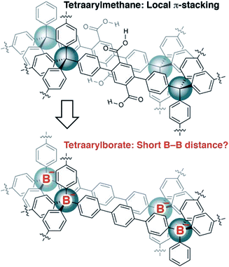
Recently, we reported the synthesis of porous organic polymers that display exceptional ammonia adsorption, apparently as a result of the interpenetration of individual networks (Fig. 2).18 Interpenetration of the networks places two or more carboxylic acid functional groups in close proximity, allowing for the cooperative enhancement of effective acidity. Making a conceptual substitution, we hypothesized that the tetraarylborates incorporated into a similar interpenetrated network would be held sufficiently close to provide highly conductive solid electrolytes. Herein, we report our successful realization of such materials and demonstrate that they are amenable to straightforward chemical modification, making these polymers an intriguing platform for solid electrolyte development.
Results and discussion
At the outset of our investigations, only a single example of a fourfold cross coupling reaction occurring at a tetraarylborate center had been reported (i.e., 6 → 7, Scheme 1).19 We investigated the polymerization of both lithium tetraarylborate 6, as well as its triethylammonium analog 8. Buchwald's second generation XPhos precatalyst20 was used under Sonogashira cross-coupling conditions similar to those known to be compatible with potassium aryltrifluoroborates,21 which provided productive polymerizations with 1,4-diethynylbenzene (9). The resulting insoluble polymers exhibited elemental analyses and infrared spectra consistent with the expected structures, suggesting a high extent of reaction. In contrast to previous reports of neutral phenylene ethynylene-linked porous polymers,22 these polymers were non-porous, as determined by nitrogen gas adsorption measurements performed at 77 K. In addition, the lack of peaks arising from powder X-ray diffraction suggests that the polymers do not adopt a specific network structure (e.g., diamondoid, etc.). We assume an irregular, densely packed and cross-linked material. Although these materials display no permanent porosity, the triethylammonium cations initially delivered with monomer 8 could be easily exchanged with LiOH, offering a means to use other basic metal salts (e.g., NaOH, KOH) to generate a family of solid electrolytes from a single parent polymer.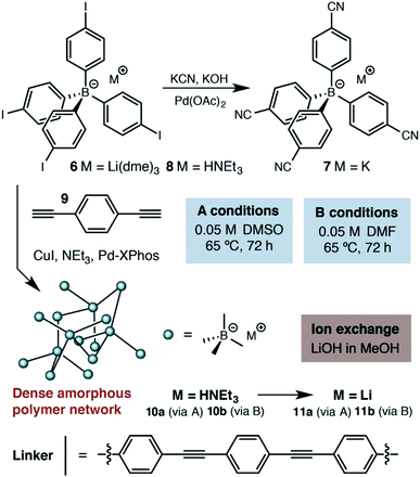 | ||
| Scheme 1 Synthetic approach to the first generation solid lithium electrolyte based on a (proteo)phenylborate monomer. | ||
Accordingly, we focused our initial investigations on polymers derived from triethylammonium borate building blocks. Notably, materials polymerized from DMSO solutions (10a) showed a moderate ionic conductivity of 3.6 × 10⁻⁵ S cm−1 at 27 °C (Fig. 3) after a rigorous sequence of ion exchange (11a), washing with low boiling solvents (MeOH, THF), drying in vacuo, and readsorption of small quantities of propylene carbonate. During our initial attempts to improve the conductivity of this material by optimizing the synthetic procedure, we were confronted by a striking result: while polymers produced in DMF solution (10b and 11b) presented elemental analysis and infrared spectra indistinguishable from the polymers produced in DMSO, they were universally non-conductive (<10−8 S cm−1). SEM images of these materials, conversely, did provide noteworthy contrast (Fig. 4). Conductive materials synthesized in DMSO have a smooth, continuous appearance, whereas the nonconductive polymers prepared in DMF appear rough on the micron scale. Our hypothesis for the effect of this morphology change on conductivity will be discussed further below.
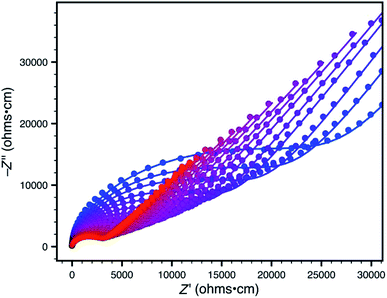 | ||
| Fig. 3 Variable-temperature AC impedance spectra for 11a taken from 300 K (blue points) to 373 K (red points) in 5 K intervals from 303 K on. Lines represent fit to an equivalent circuit diagram shown in the ESI.† | ||
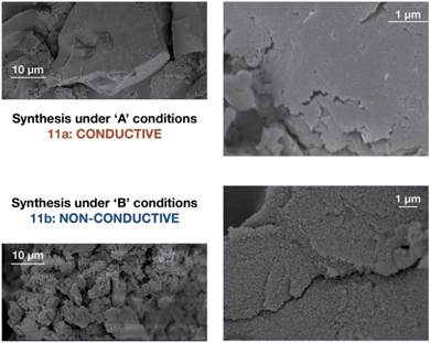 | ||
| Fig. 4 Scanning electron micrographs of borate polymers produced in DMSO (11a above) and DMF (11b below). | ||
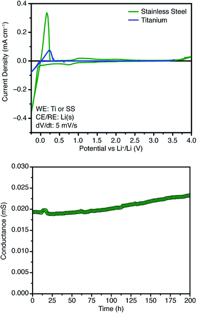
Further attempts to improve the conductivity of these materials through optimization of the synthetic procedure failed, so we next sought polymers with improved conductivity by weakening the lithium–borate interaction through perfluorination of the aromatic rings of the borate anions.23 Polymerization of perfluorinated arylborate monomer 12 under our standard conditions again provided a non-porous cross-linked polymer (Scheme 2, 13). After exchange of the triethylammonium cations to Li+, the resulting polymer (14), exhibited nearly an order of magnitude higher ionic conductivity of 2.7 × 10⁻⁴ S cm−1 at 28 °C. This value approaches that necessary for incorporation into working Li-ion battery cells.4 Cyclic voltammetry measurements using both stainless steel and titanium working electrodes also suggested that this initial material represented an appropriate starting point for solid electrolyte development (Fig. 5). Our initial fluorinated polymer (14) shows oxidative stability to approximately 3.5–3.7 V (vs. Li/Li+) at 90 °C. This may be directly applicable to cells incorporating iron phosphate cathodes,24 but is lower than expected considering the constituent parts have been reported in electrolytes with superior oxidative stabilities. The observed electrochemical reactivity may be the result of trace impurities in the synthesized material. Additionally, this material displayed acceptable initial stability to lithium metal. A symmetric Li(s)|electrolyte|Li(s) cell was constructed, and the ionic conductivity was measured every hour for 200 hours total. Over this period, no decrease in total conductance (i.e. including ionic and interfacial impedance) was observed. With the perfluorinated borate node identified as a suitable initial building block for a solid electrolyte, we were next able to shift our attention to varying the network structure through changes in polymerization conditions, as well as the structure of the linear bis-alkyne linker.
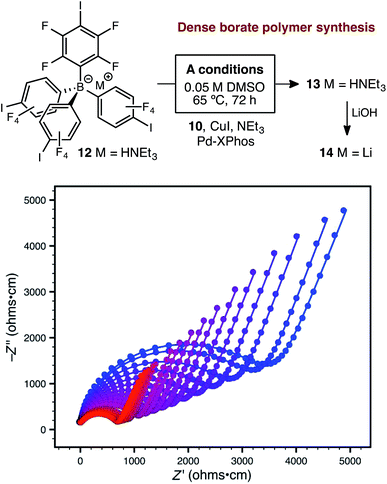 | ||
| Scheme 2 Synthetic approach to perfluorinated polymer 14 and variable-temperature ac impedance spectra taken from 300 K (blue circles) to 373 K (red circles) in 5 K intervals from 303 K on. Lines represent fit to an equivalent circuit diagram shown in the ESI.† | ||
Synthetic conditions that delivered porous anionic polymers were identified by utilizing the corresponding brominated monomer 15, which more closely resembles those described by Thomas for a similar porous polymer linked by 1,3,5-triethynylbenzene.25 Under these conditions, the resulting tetraarylborate polymer (16) displayed permanent porosity (Scheme 3). Therefore, the precise synthetic conditions, rather than the network topology, were responsible for the lack of permanent porosity in polymers 11 and 14. After soaking with excess LiPF6 to exchange any transition metal or organic cation impurities and subsequent thorough washing to remove excess lithium, BET surfaces areas on the order of 480 m2 g−1 were measured (see ESI†). The particle morphology of these samples was also rough (see Fig. S15†), similar to the non-conductive, non-porous samples of 14. Likewise, the porous materials proved to be over an order of magnitude less conductive than their non-porous analog 14 (1.4 × 10⁻⁵ S cm−1 for 16vs. 2.7 × 10⁻⁴ S cm−1 for 14). In fact, in this case, the fluorinated polymer 16 displays lower conductivity than the non-fluorinated analog 11a prepared from DMSO. Surprisingly, while dense fluorinated polymer 14 and its porous analog 16 differ in terms of bulk conductivity by over an order of magnitude, they display approximately the same activation energy (Fig. 6). Therefore, the overall particle morphology, not permanent porosity, appears to be the most useful predictor of bulk conductivity across a pressed pellet.
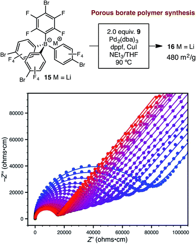 | ||
| Scheme 3 Synthetic approach to porous polymer 16 and variable-temperature ac impedance spectra taken from 300 K (blue circles) to 373 K (red circles) in 5 K intervals from 303 K on. Lines represent fit to an equivalent circuit diagram shown in the ESI.† | ||
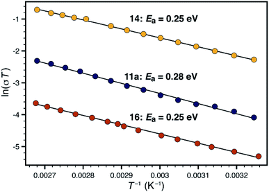 | ||
| Fig. 6 Comparison of activation energies for non-porous polymers 11a (blue) and 14 (yellow), and porous polymer 16 (red). | ||
When considering transport through the polymer particles, two opposing features must be considered. While the non-porous materials may feature a favorable average anion-to-anion distance, and a higher density of charge carriers, the resulting conduction pathway could be highly tortuous or otherwise hindered. The porous materials might feature open transport pathways, but would require a longer ion hopping distance. In our case, the higher spatial concentration of charge carriers in the dense materials seems to lead to higher performance in polymer 14. However, these considerations still cannot explain the dramatic difference in conductivity between rough and smooth materials (i.e.11avs.11b).
An additional, and perhaps more compelling explanation, however, is that bulk conductivity is highly dependent on surface conduction pathways. A mechanism based predominantly on grain boundary conduction would help to explain the overwhelming dependence of conductivity on morphology, where chemically identical polymers 11a and 11b differ in conductivity by over four orders of magnitude. The porous and non-porous materials would still feature different densities of charge carriers at the grain boundaries, allowing for large differences in bulk conductivity values in materials with identical activation energies (i.e. 14vs.16). We currently favor the following: the micron-sized particles imaged in Fig. 4 are not single polymer particles, but instead, are aggregates of much smaller individual particles. In the case of highly conductive materials such as 11a or 14, efficient packing of exceedingly small particles allows for a high density of surface conduction pathways. The 'rough' nature of non-conductive materials such as 12b is actually the visualization of individual polymer particles, which by simple geometry, feature fewer unbroken conduction pathways between the electrodes. This type of behavior would not be unprecedented. For example, CaF2 displays greater than an order of magnitude increase in fluoride ion conductivity upon decreasing the average crystallite size from 200 nm to 9 nm.26
As has been very well demonstrated in the context of block copolymers,27 ethylene glycol domains might provide effective conduction pathways for lithium ions, potentially in the absence of organic solvents, even if Li+ ion conduction occurred only along the interparticle boundaries. We therefore tethered two tri(ethylene glycol) moieties to the 1,4-diethynybenzene linker (17, Scheme 4) in order to evaluate this possibility. Our standard synthetic procedure using triethylammonium borate 12 provided the expected polymer in reasonable yield. However, we were surprised to find that no significant ion exchange occurred upon exposure to lithium hydroxide. Therefore, we generated the lithium-containing material 19 by polymerizing lithium borate 18, which proved to be free of nitrogen-containing impurities (i.e., triethylammonium cations generated during the Sonogashira polymerization) by elemental analysis.
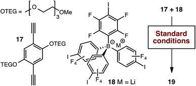 | ||
| Scheme 4 Alternative synthetic approach for the production of tri(ethylene glycol) substituted polymer 19. | ||
Although glycol-containing polymer 19 was not conductive without additional solvent, it did yield an important performance contrast with 14 when incorporated in symmetric Li(s)|borate polymer|Li(s) cells.
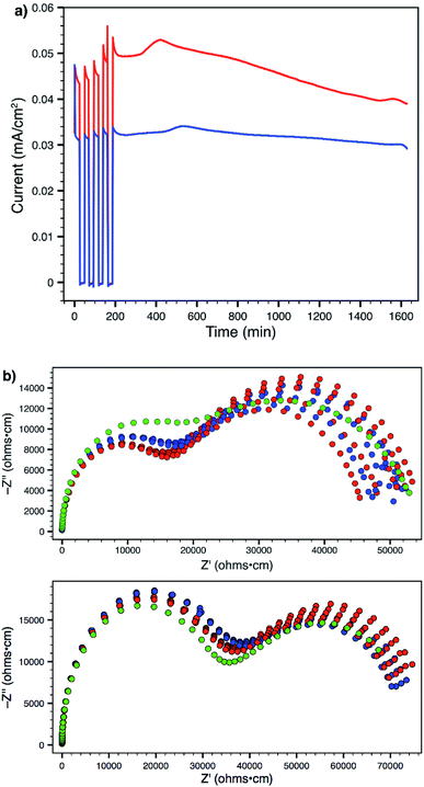
Using a 300 mV applied potential (versus open circuit), we subjected polymers 14 and 19 to four 22 min potential steps and relaxations, followed by a 24 h hold, as an initial assessment of the lithium transference number and stability towards lithium metal under operating conditions (Fig. 7a). Polymer 14 exhibited higher ionic conductivity and larger current in response to the applied voltage. However, it also displayed greater current decay during both the 22 minute steps (indicating a lower transference number) as well as over the course of the entire experiment (indicating lower stability to lithium metal). Comparison of the current between the beginning and end of the potential step yields a transference number (tLi+) of 0.89 for 14 and 0.93 for 19 (average of four pulses). At the end of every step and relaxation, as well as at the end of the entire experiment, ac impedance spectra were collected (Fig. 7b), which also indicate that polymer 19 is more stable to the experimental conditions. Both materials showed little or no change in interfacial impedance, supporting the technique used for calculating transference number;28 tri(ethylene glycol) substituted polymer 19 actually displayed a slight increase in ionic conductivity over the course of the experiment (green data). This behaviour was in sharp contrast to that of 14, which suffered an obvious decrease. The ability to make a meaningful impact on such material parameters through straightforward chemical substitution of one of the monomer units should provide a direct avenue to further improve the performance of these materials and single-ion conductors.
Conclusions and outlook
Many traditional heteroatom-containing polymers, such as polyethylene oxide, polyacrylates, polyacrylamides, polyacrylonitrile, polystyrenesulfonate, or polyvinylidene fluoride have formed the basis of novel electrolytes for lithium ion batteries, either as pure components,29 as composite materials with inorganic filler,30 or as gel electrolytes.31 Here, we have introduced a new organic polymer electrolyte, which has strong single ion-conducting character (tLi+ 0.89–0.93), moderate activation energies (0.25–0.28 eV), and promising room temperature conductivities (up to 2.7 × 10⁻⁴ S cm−1). While a full evaluation of the mechanical properties of these polymers has not been completed, their 3D-crosslinked nature is comparable in many senses to metal–organic frameworks, where Young's moduli around 10 GPa have already been measured,32 and shear moduli above 10 GPa have been predicted computationally for a number of frameworks.33 Although analogous measurements have not been made on PAF-type porous materials, initial computational work suggests that these materials should display similar rigidity.34 Although the most reasonable current mechanism for conductivity appears to invoke the particle surface exclusively, chemical modification of the monomer units provides a straightforward approach to further tune performance. With conductivity metrics that are already competitive with more mature polymer platforms, further investigations based upon non-coordinating arylborate building blocks should prove to be a promising new direction in solid electrolyte design.Acknowledgements
Initial work on borate polymers 10, 11, and 14 was funded by the Center for Gas Separations Relevant to Clean Energy Technologies, an Energy Frontier Research Center funded by the U.S. Department of Energy, Office of Science, Office of Basic Energy Sciences from award DE-SC0001015. Further research towards functionalized materials, such as 19, and ongoing work, is being funded by Bosch through a Bosch Energy Research Network (BERN) grant. A. A., G. W. C., and W. R. D. acknowledge support from the National Science Foundation (NSF) under the Center for Sustainable Polymers CHE-1413862. Jordan Axelson is thanked for assistance in gathering elemental analyses and 13C NMR spectra. We further thank Arkema for fellowship support of M. L. A.Notes and references
- C.-X. Zu and H. Li, Energy Environ. Sci., 2011, 4, 2614 CAS.
- (a) J. Cabana, L. Monconduit, D. Larcher and M. R. Palacín, Adv. Mater., 2010, 22, E170 CrossRef CAS PubMed; (b) D. Larcher, S. Beattie, M. Morcrette, K. Edström, J.-C. Jumas and J.-M. Tarascon, J. Mater. Chem., 2007, 17, 3759 RSC; (c) C.-M. Park, J.-H. Kim, H. Kim and H.-J. Sohn, Chem. Soc. Rev., 2010, 39, 3115 RSC; (d) F. Cheng and J. Chen, Chem. Soc. Rev., 2012, 41, 2172 RSC.
- F. Cheng, J. Liang, Z. Tao and J. Chen, Adv. Mater., 2011, 23, 1695 CrossRef CAS PubMed.
- J. B. Goodenough and Y. Kim, Chem. Mater., 2009, 22, 587 CrossRef.
- K. Xu, Chem. Rev., 2004, 104, 4303 CrossRef CAS PubMed.
- (a) I. Yoshimatsu, T. Hirai and J. Yamaki, J. Electrochem. Soc., 1988, 162, 2422 CrossRef; (b) J. M. Tarascon and M. Armand, Nature, 2001, 414, 359 CrossRef CAS PubMed.
- P. Arora, R. E. White and M. Doyle, J. Electrochem. Soc., 1998, 145, 3647 CrossRef CAS.
- D. T. Hallinan Jr and N. P. Balsara, Annu. Rev. Mater. Res., 2013, 43, 503 CrossRef.
- (a) J.-N. Chazalviel, Phys. Rev. A, 1990, 42, 7355 CrossRef CAS PubMed; (b) M. Rosso, T. Gobron, C. Brissot, J.-N. Chazalviel and S. Lascaud, J. Power Sources, 2001, 97–8, 804 CrossRef.
- C. Monroe and J. Newman, J. Electrochem. Soc., 2005, 152, A396 CrossRef CAS.
- (a) G. M. Stone, S. A. Mullin, A. A. Teran, D. T. Hallinan Jr, A. M. Minor, A. Hexemer and N. P. Balsara, J. Electrochem. Soc., 2012, 159, A222 CrossRef CAS; (b) R. Khurana, J. L. Schaefer, L. A. Archer and G. W. Coates, J. Am. Chem. Soc., 2014, 136, 7395 CrossRef CAS PubMed.
- S. C. Levy, J. Power Sources, 1997, 68, 75 CrossRef CAS.
- For particularly relevant examples, see: (a) W. Xu, M. D. Williams and C. A. Angell, Chem. Mater., 2002, 14, 401 CrossRef CAS; (b) S. Tabata, T. Hirakimoto, H. Tokuda, M. A. B. H. Susan and M. Watanabe, J. Phys. Chem. B, 2004, 108, 19518 CrossRef CAS; (c) Y. S. Zhu, X. J. Wang, Y. Y. Hou, X. W. Gao, L. L. Liu, Y. P. Wu and M. Shimizu, Electrochim. Acta, 2013, 87, 113 CrossRef CAS.
- For particularly relevant examples, see: (a) X.-G. Sun, C. L. Reeder and J. B. Kerr, Macromolecules, 2004, 37, 2219 CrossRef CAS; (b) X.-G. Sun and J. B. Kerr, Macromolecules, 2006, 39, 362 CrossRef CAS; (c) Y. S. Zhu, X. W. Gao, X. J. Wang, Y. Y. Hou, L. L. Liu and W. P. Wu, Electrochem. Commun., 2012, 22, 29 CrossRef CAS.
- X. Wang, Z. Liu, C. Zhang, Q. Kong, J. Yao, P. Han, W. Jiang, H. Xu and G. Cui, Electrochim. Acta, 2013, 92, 132 CrossRef CAS.
- (a) U. H. Choi, S. Liang, M. V. O'Reilly, K. I. Winey, J. Runt and R. H. Colby, Macromolecules, 2014, 47, 3145 CrossRef CAS; (b) S. Liang, U. H. Choi, W. Liu, J. Runt and R. H. Colby, Chem. Mater., 2012, 24, 2316 CrossRef CAS.
- K.-J. Lin, K. Li and J. K. Maranas, RSC Adv., 2013, 3, 1564 RSC.
- J. F. van Humbeck, T. M. McDonald, X. Jing, B. M. Wiers, G. Zhu and J. R. Long, J. Am. Chem. Soc., 2014, 136, 2432 CrossRef CAS PubMed.
- N. Malek, T. Maris, M. Simard and J. D. Wuest, J. Am. Chem. Soc., 2005, 127, 5910 CrossRef CAS PubMed.
- T. Kinzel, Y. Zhang and S. L. Buchwald, J. Am. Chem. Soc., 2010, 132, 14073 CrossRef CAS PubMed.
- D.-S. Kim and J. Ham, Org. Lett., 2010, 12, 1092 CrossRef CAS PubMed.
- (a) A. Laybourn, R. Dawson, R. Clowes, T. Hasell, A. I. Cooper, Y. Z. Khimyak and D. J. Adams, Polym. Chem., 2014, 5, 6325 RSC; (b) J. R. Holst, E. Stöckel, D. J. Adams and A. I. Cooper, Macromolecules, 2010, 43, 8531 CrossRef CAS; (c) J.-X. Jiang, A. Trewin, F. Su, C. D. Wood, H. Niu, J. T. A. Jones, Y. Z. Khimyak and A. I. Cooper, Macromolecules, 2009, 42, 2658 CrossRef CAS; (d) E. Stöckel, X. Wu, A. Trewin, C. D. Wood, R. Clowes, N. L. Campbell, J. T. A. Jones, Y. Z. Khimyak, D. J. Adams and A. I. Cooper, Chem. Commun., 2009, 212 RSC; (e) W. Lu, D. Yuan, D. Zhao, C. I. Schilling, O. Plietzsch, T. Muller, S. Bräse, J. Guenther, J. Blümel, R. Krishna, Z. Li and H.-C. Zhou, Chem. Mater., 2010, 22, 5964 CrossRef CAS.
- W. E. Piers and T. Chivers, Chem. Soc. Rev., 1997, 26, 345 RSC.
- A. K. Padhi, K. S. Nanjundaswamy and J. B. Goodenough, J. Electrochem. Soc., 1997, 144, 1188 CrossRef CAS.
- S. Fischer, J. Schmidt, P. Strauch and A. Thomas, Angew. Chem., Int. Ed., 2013, 52, 12174 CrossRef CAS PubMed.
- (a) W. Puin, S. Rodewald, R. Ramlau, P. Heitjans and J. Maier, Solid State Ionics, 2000, 131, 159 CrossRef CAS; (b) J. Maier, Nat. Mater., 2005, 4, 805 CrossRef CAS PubMed.
- For pertinent reviews, see: (a) A.-V. Ruzette and L. Leibler, Nat. Mater., 2005, 4, 19 CrossRef CAS PubMed; (b) J. Y. Song, Y. Y. Wang and C. C. Wan, J. Power Sources, 1999, 77, 183 CrossRef CAS.
- P. G. Bruce, J. Evans and C. A. Vincent, Solid State Ionics, 1988, 28–30, 918 CrossRef.
- J. W. Fergus, J. Power Sources, 2010, 195, 4554 CrossRef CAS.
- A. M. Stephan and K. S. Nahm, Polymer, 2006, 47, 5952 CrossRef CAS.
- A. M. Stephan, Eur. Polym. J., 2006, 42, 21 CrossRef.
- S. Bundschuh, O. Kraft, H. K. Arslan, H. Gliemann, P. G. Weidler and C. Wöll, Appl. Phys. Lett., 2012, 101, 101910 CrossRef.
- S. S. Han and W. A. Goddard III, J. Phys. Chem. C, 2007, 111, 15185 CAS.
- L. Huang, Z. Xiang and D. Cao, J. Mater. Chem. A, 2013, 1, 3851 CAS.
Footnote |
| † Electronic supplementary information (ESI) available: Adsorption isotherms, IR spectra, synthetic procedures, characterization data, equivalent circuit diagrams and additional SEM images. See DOI: 10.1039/c5sc02052b |
| This journal is © The Royal Society of Chemistry 2015 |

