DOI:
10.1039/C5RA16538E
(Paper)
RSC Adv., 2015,
5, 89689-89697
Electrochemical capacitance of a carbon quantum dots–polypyrrole/titania nanotube hybrid
Received
17th August 2015
, Accepted 27th September 2015
First published on 30th September 2015
Abstract
A carbon quantum dots modified polypyrrole/titania (CQDs–PPy/TiO2) nanotube hybrid was designed as a supercapacitor electrode material for energy storage. CQDs–PPy/TiO2 was prepared by incorporating CQDs-hybridized PPy into a well-aligned titania nanotube array. CQDs–PPy/TiO2 exhibited a highly-ordered heterogeneous coaxial nanotube structure. A CQDs hybridized modification could improve the electrical conductivity of PPy. The charge transfer resistance decreased from 22.4 mΩ cm−2 to 9.3 mΩ cm−2 and the ohmic resistance decreased from 0.817 to 0.154 Ω cm−2 when PPy/TiO2 was converted into the CQDs–PPy/TiO2 nanotube hybrid. The specific capacitance was accordingly enhanced from 482 F g−1 (or 161 mF cm−2) for PPy/TiO2 to 849 F g−1 (or 212 mF cm−2) for CQDs–PPy/TiO2 at a current density of 0.5 A g−1. The capacitance retention was slightly increased from 78.5% to 89.3% after 2000 cycles at a high current density of 20 A g−1. The effective incorporation of CQDs into PPy could simultaneously increase the electrochemical capacitance and cycle stability of PPy, leading to a superior electrochemical performance. A flexible solid-state supercapacitor based on the CQDs–PPy nanohybrid exhibited the stable capacitive performance in both planar and bent states. CQDs-hybridized PPy presented promising applications as a supercapacitor electrode material for energy storage.
1. Introduction
Nowadays, conducting polymers have been widely explored for high performance pseudocapacitors because of their excellent energy storage capacity, low cost, high availability and environmental friendliness.1–6 Polypyrrole (PPy) has a unique π-conjugated system and can provide an effective route for the flow of electronic charges.7 PPy has been extensively studied for electrochemical energy storage application.8,9 The microstructure of PPy is the crucial issue to determine its electrochemical performance.10 Nanostructured electrode materials generally exhibit superior properties compared to their bulk counterparts due to their larger surface area and shorter charge transfer pathway.11,12 The well-aligned titania (TiO2) nanotube array has been explored as the support of electrodes because of the high surface area and chemical/electrochemical stability.13 The highly ordered TiO2 nanotube array with the controlled morphologies can be well prepared by an electrochemical anodization method.14,15 The hybrid of PPy and TiO2 with a well-designed nanostructure and high surface area can be regarded as a suitable electrode material for electrochemical supercapacitors.16 However, the main drawback using PPy as a supercapacitor electrode is mainly due to its inherent low electrical conductivity and poor stability during the cycling process.17 Several approaches have been proposed to overcome these shortcomings, which include using the substrate of titanium nitride to improve conductivity5,18–21 and adding conductive nanoparticles to improve the rate of electron transport.22–26 Patil et al. have reported the formation of a polypyrrole/polyacrylic acid/silver composite electrode by chemical polymerization via a simple and cost effective dip coating technique.27 Dhibar et al. have fabricated a silver–polyaniline/multiwalled carbon nanotubes nanocomposite by a low-cost and simple process.28 Wei et al. have directly deposited polypyrrole–silver composites on nickel foam via the redox reaction between pyrrole and silver nitrate.29 A synergistic effect between PPy and conductive nanoparticles has been presumed to enhance the mechanical and conducting properties. Commonly, carbon nanomaterials, such as carbon quantum dots, carbon nanotubes and graphene, have attracted great interest due to high conductivity, long cycle life and good cycling stability for supercapacitor applications.30–32 However, the drawback of low capacitance still needs to be overcome. The overall aim of this study is to develop a conductive hybrid material to improve supercapacitance performance and the cycling stability of PPy. Water-soluble CQDs was used to directly incorporate into bulk PPy to form a highly conductive CQDs–PPy composite film during the electropolymerization process.
In this study, the CQDs–PPy/TiO2 nanotube hybrid was synthesized by incorporating CQDs-hybridized PPy into a TiO2 nanotube array using an electrochemical polymerization method. Highly conductive CQDs were used to improve the electrical conductivity and electroactivity of PPy. TiO2 nanotube hybrid as an electrode substrate was used to improve the utilization of PPy. Therefore, CQDs–PPy/TiO2 nanotube hybrid is expected to exhibit superior capacitance performance and good cycling stability as well.
2. Experimental
2.1 Materials
Titanium sheet (Ti, purity > 99.6%, thickness 0.2 mm) was purchased from Good fellow Cambridge Ltd. Pyrrole monomer (Py, purity > 98%), carbon rod (C, purity > 99.9%) and other chemicals (analytical grade) were purchased from Sinopharm chemical company and used without further purification. All aqueous solutions were prepared with double-distilled water.
2.2 Synthesis of CQDs–PPy/TiO2 nanotube hybrid
CQDs–PPy/TiO2 nanotube hybrid was synthesized using a TiO2 nanotube array as an electrode substrate. First, the TiO2 nanotube array was directly formed on a Ti sheet by an anodization process, which was conducted at 30 V for 2 h in a water and ethylene glycol mixture (volume ratio, 50/50) containing 0.2 M ammonium fluoride and 0.5 M phosphoric acid. An annealing treatment at 450 °C for 2 h was conducted to form an anatase TiO2 nanotube array. Then, a normal pulse voltammetry deposition method was adapted to synthesize CQDs–PPy/TiO2 nanotube hybrid in a three-electrode system using a TiO2 nanotube array as a working electrode, Pt as a counter electrode and Hg/Hg2Cl2 as a reference electrode. The aqueous reaction solution contained 0.001 M carbon quantum dots, 0.15 M pyrrole monomer and 0.1 M lithium perchlorate (LiClO4) supporting electrolyte. PPy/TiO2 nanotube hybrid was also prepared in the same abovementioned aqueous solution without carbon quantum dots. The pulse potential was increased from 0.7 to 1.1 V with a pulse potential increase of 0.001 V. The pulse width was 0.06 s and the pulse period was 4 s. The as-formed CQDs–PPy/TiO2 and PPy/TiO2 nanotube hybrid was repeatedly washed with double-distilled water and finally dried at room temperature. The flexible supercapacitor application was investigated using the CQDs–PPy nanohybrid as a freestanding film electrode. A flexible solid-state supercapacitor was constructed using the CQDs–PPy nanohybrid film as freestanding film electrode. First, CQDs–PPy nanohybrid film was fabricated by dissolving the TiO2 template from CQDs–PPy/TiO2 nanotube hybrid in 2.0 M hydrofluoric acid aqueous solution. PVA/H2SO4 gel electrolyte was prepared according to the previously reported method.3 CQDs–PPy nanohybrid film electrode was fabricated by spreading two pieces of CQDs–PPy nanohybrid films on both sides of a porous dialysis membrane. Herein, the porous dialysis membrane was initially saturated with PVA/H2SO4 gel electrolyte. The flexible solid-state supercapacitor was assembled by wrapping the CQDs–PPy nanohybrid film electrode with polyethylene terephthalate (PET) film, and connecting the CQDs–PPy nanohybrid film electrode with copper wires.
2.3 Characterization and electrochemical measurements
The surface morphology and microstructure of the electrode materials were investigated using field emission scanning electron microscopy (FESEM, Zeiss Ultra-Plus) and transmission electron microscopy (TEM, JEM-2100). Raman spectroscopy was performed using a Raman spectrometer (Raman, Renishaw Invia Reflex System) in the range of 100–2000 cm−1. This device was equipped with a He–Ne laser beam operating at a 785 nm wavelength. Electrochemical analysis and measurements were carried out using an electrochemical workstation (CHI760C, CH Instruments) in a conventional three-electrode system with a Pt sheet as a counter electrode, KCl-saturated calomel electrode as a reference electrode, and CQDs–PPy/TiO2 and PPy/TiO2 nanotube hybrid as a working electrode. The cyclic voltammetry (CV) was conducted in 1 M H2SO4 electrolyte solution. The galvanostatic charge–discharge (GCD) measurements were performed in 1 M H2SO4 electrolyte solution under a controlled current density and potential window. Electrochemical impedance spectroscopy (EIS) measurements were implemented at 0.2 V vs. SCE with an ac-voltage amplitude of 5 mV over the frequency range of 0.01–100![[thin space (1/6-em)]](https://www.rsc.org/images/entities/char_2009.gif) 000 Hz after cyclic voltammetry tests in 1 M Na2SO4 electrolyte solution by using an electrochemical analyzer (IM6e ZAHNER Elektrik, Germany). The electrochemical measurement of flexible CQDs–PPy supercapacitor was conducted using a two-electrode testing system.
000 Hz after cyclic voltammetry tests in 1 M Na2SO4 electrolyte solution by using an electrochemical analyzer (IM6e ZAHNER Elektrik, Germany). The electrochemical measurement of flexible CQDs–PPy supercapacitor was conducted using a two-electrode testing system.
3. Results and discussion
3.1 Electrochemical deposition process
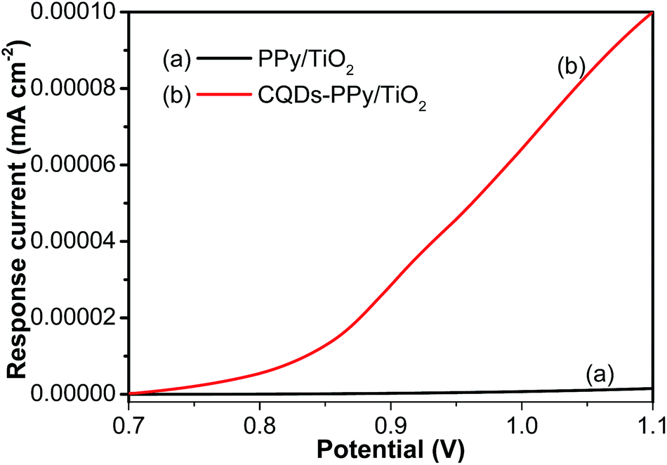
Fig. 1 shows the response current curves of the CQDs–PPy/TiO2 and PPy/TiO2 nanotube hybrid during the electropolymerization synthesis process. The increase in current was insignificant when the initial electrode potential was increased from 0.7 to 0.80 V. The electrochemical polymerization reaction of pyrrole monomer occurs predominately at an anodic potential above 0.8 V vs. SCE. The response current was very low in this initial reaction period below, i.e. 0.8 V. A quick enhancement of the response current could be then achieved when the electrode potential was further increased from 0.8 to 1.1 V. This indicates that the ohmic resistance of as-formed CQDs–PPy/TiO2 and PPy/TiO2 gradually decreases along with continuous electrodeposition of PPy on a TiO2 nanotube array.16 Comparatively, the response current was increased from 7.7 × 10⁻⁸ mA cm−2 for PPy/TiO2 to 5.5 × 10⁻⁶ mA cm−2 for CQDs–PPy/TiO2 at a critical potential of 0.7 V. The presence of CQDs in the pyrrole monomer electrolyte could effectively promote the electropolymerization reaction, leading to the formation of a highly conductive CQDs–PPy/TiO2 electrode material.
 |
| | Fig. 1 Response current curves of (a) PPy/TiO2 and (b) CQDs–PPy/TiO2 nanotube hybrid in a normal pulse voltammetry deposition process. | |
3.2 Microstructure characterization
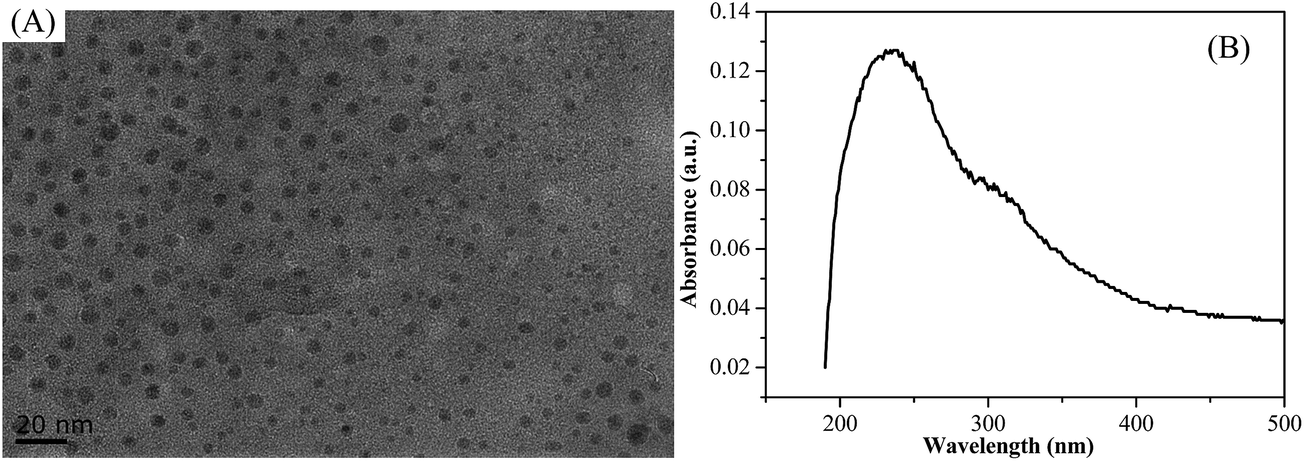
TEM and SEM were employed to investigate the morphologies and microstructures of CQDs and CQDs–PPy/TiO2 nanotube hybrid. Fig. 2(A) shows TEM images of the CQDs. It can be seen that the CQDs had a spherical shape and a narrow particle distribution of 3–7 nm. All the CQDs were uniformly dispersed and separated from each other without any aggregation. Fig. 2(B) shows the UV-Vis absorption spectrum of CQDs. The appearance of maximum absorption wavelength at 235 nm is ascribed to the formation of CQDs.33,34
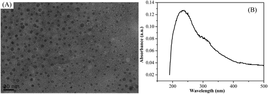 |
| | Fig. 2 (A) TEM image and (B) UV-Vis absorption spectrum of CQDs in an aqueous solution. | |
Fig. 3 shows SEM images of a TiO2 nanotube array and CQDs–PPy/TiO2 nanotube hybrid. TiO2 has a well-ordered and independent nanotube array structure with an average inner diameter of 120–150 nm, a wall thickness of 10–20 nm and a total length of 1.1 μm (Fig. 3(A and B)). CQDs–PPy/TiO2 exhibited a highly-ordered heterogeneous coaxial nanotube structure and all these nanotube walls were inclined to bond together. An average wall thickness of about 65–115 nm was found with an inner nanotube diameter of 35–90 nm. The total length of CQDs–PPy/TiO2 was approximately 1.2 μm, which was close to or a little higher than the length of the bare TiO2 nanotubes. The ordered and coaxial CQDs–PPy/TiO2 nanotube hybrid provided an effective interface area to shorten the ion diffusion path and electron transfer path, which was beneficial to form a good electrically conductive channel for supercapacitor applications.
 |
| | Fig. 3 SEM images of (A) top surface view and (B) cross-section view of TiO2 nanotube array; (C) top surface view and (D) cross-section view of CQDs–PPy/TiO2 nanotube hybrid. | |
3.3 Raman spectroscopy analysis
Raman spectroscopy measurements were used to confirm the formation of the as-prepared CQDs–PPy/TiO2 nanotube hybrid. Fig. 4 shows the Raman spectra of CQDs, PPy and CQDs–PPy/TiO2 in the range of 100–2000 cm−1. Regarding CQDs, two characteristic Raman scattering peaks at 1376 and 1572 cm−1 are ascribed to the disordered D band and the ordered G band, respectively.35 The broad peak at around 450 cm−1 is ascribed to the as-anodized amorphous TiO2 nanotube sheet substrate that was used to support the CQDs. For the PPy, the Raman scattering peak at 1602 cm−1 is assigned to the C![[double bond, length as m-dash]](https://www.rsc.org/images/entities/char_e001.gif) C stretching vibration. The peak at 1485 cm−1 is assigned to C–C stretching vibration. The peak at 1396 cm−1 is assigned to the C–N stretching vibration. The peak at 1245 cm−1 represents the C–H in-plane bending vibration. The peaks at 1043 and 930 cm−1 are assigned to C–H ring deformation vibration.36,37 In view of the CQDs–PPy/TiO2 nanotube hybrid, the main Raman scattering peaks were located at 1590, 1373 and 935 cm−1. Comparatively, the characteristic Raman peaks of the CQDs–PPy/TiO2 nanotube hybrid were very similar to those of CQDs and PPy. This proves that CQDs–PPy/TiO2 nanotube hybrid included CQDs and PPy on the base of the TiO2 nanotube array through an electro-polymerization deposition process.
C stretching vibration. The peak at 1485 cm−1 is assigned to C–C stretching vibration. The peak at 1396 cm−1 is assigned to the C–N stretching vibration. The peak at 1245 cm−1 represents the C–H in-plane bending vibration. The peaks at 1043 and 930 cm−1 are assigned to C–H ring deformation vibration.36,37 In view of the CQDs–PPy/TiO2 nanotube hybrid, the main Raman scattering peaks were located at 1590, 1373 and 935 cm−1. Comparatively, the characteristic Raman peaks of the CQDs–PPy/TiO2 nanotube hybrid were very similar to those of CQDs and PPy. This proves that CQDs–PPy/TiO2 nanotube hybrid included CQDs and PPy on the base of the TiO2 nanotube array through an electro-polymerization deposition process.
 |
| | Fig. 4 Raman spectra of the CQDs, PPy and CQDs–PPy/TiO2 nanotube hybrid. | |
3.4 Electrochemical impedance spectroscopy analysis
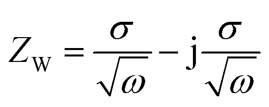
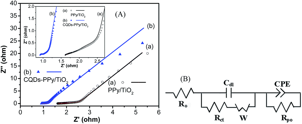
Electrochemical impedance spectroscopy measurements were carried out to evaluate the charge transfer and ion diffusion properties of electrode materials. Fig. 5 shows Nyquist plots and an equivalent circuit of CQDs–PPy/TiO2 and PPy/TiO2 nanotube hybrid at an ac-voltage amplitude of 5 mV and frequency range of 100 kHz to 10 MHz in 1 M H2SO4 aqueous electrolyte. Nyquist plots of CQDs–PPy/TiO2 and PPy/TiO2 nanotube hybrid showed a small semicircle in the high frequency region and a straight line along the imaginary axis in the low frequency region. The intersection of the curves at the real impedance axis in the high-frequency region reflects total ohmic resistance (Ro), including resistance of electrolyte, intrinsic resistance of electrode material, and contact resistance at interface of electroactive material and current collector. The high-frequency impedance arc is attributed to the charge-transfer resistance (Rct) between electroactive PPy and electrolyte during the electrochemical process. The double layer capacitance (Cdl) is attributed to the charge close to the porous interface of the nanotube hybrid. The Warburg element (W) represents the mass transport of reactants to and/or products from the electrode surface that may determine the electrochemical reaction rate of electroactive materials.38 The constant phase elements (CPE) are used to account for the double layer capacitance and pseudocapacitance. The pore resistance (Rpo) represents the electron transfer resistance in the nanotube hybrid.39 The detailed fitting results of equivalent circuit parameters are summarized in Table 1. Ro of CQDs–PPy/TiO2 and PPy/TiO2 nanotube hybrid was 0.154 and 0.817 Ω cm−2, respectively. The corresponding Rct was 0.00931 and 0.02241 Ω cm−2, respectively. These results clearly demonstrate that CQDs improved the electrical conductivity of the CQDs–PPy/TiO2 nanotube hybrid, resulting in a higher charge transfer rate than PPy/TiO2. Cdl was 0.248 and 0.579 mF cm−2 for the CQDs–PPy/TiO2 and PPy/TiO2 nanotube hybrid, respectively. This indicates that PPy/TiO2 had a more porous interface than CQDs–PPy/TiO2 due to partial nanotubes being fully covered by PPy. The Warburg element represents the mass diffusion of reactant species in a finite or semi-infinite medium in the low frequency region.40 The corresponding Warburg impedance can be expressed by eqn (1) as follows:| |
 | (1) |
where σ is the Warburg coefficient and ω is angular frequency (ω = 2πf). W is defined by three values. W-R is the diffusion resistance and W-T is the diffusion time constant. W-P is a fractional exponent, which has a value near 0.5 with regard to the finite length diffusion characteristic.41 In general, CPE in equivalent circuit in place of a capacitor is used to compensate for non-homogeneity in the system. CPE was related to the following factors such as inhomogeneity at electrode–electrolyte interface, porosity, nature of electrode, and dynamic disorder associated with diffusion.8 CPE is defined by eqn (2) as follows:| |
 | (2) |
where Q is the frequency independent constant related to the surface and electrode substance and ω represents the angular frequency. n is a variable between 1 and 0, which is related to a non-uniform distribution due to roughness and/or the surface porosity. CPE shows different responses depending on this n value. n = 0 represents the pure resistance, whereas n = 1 represents the ideal capacitor response and n = 0.5 indicates Warburg impedance behavior. However, n > 0.5 represents moderate capacitor behavior. Herein, the n value was 0.999 and 0.962 for the CQDs–PPy/TiO2 and PPy/TiO2 nanotube hybrid, respectively. This indicates that the CQDs–PPy/TiO2 nanotube hybrid had better capacitor behavior. Rpo was 17.9 and 115 Ω cm−2 for CQDs–PPy/TiO2 and PPy/TiO2 nanotube hybrid, respectively. Ro, Rct and Rpo values could be directly used to evaluate the electrical conductivity of electrode materials. CQDs modification to PPy obviously improved its electrical conductivity, thus causing an effective pathway for charge transfer through electroactive PPy and leading to the high capacitance performance of the CQDs–PPy/TiO2 nanotube hybrid.
 |
| | Fig. 5 (A) Nyquist plots and (B) equivalent circuit of CQDs–PPy/TiO2 and PPy/TiO2 nanotube hybrid in 1 M H2SO4 solution. The inset in (A) shows the magnified Nyquist plot in high frequency range. | |
Table 1 Fitting values of equivalent circuit elements of CQDs–PPy/TiO2 and PPy/TiO2 nanotube hybrid
| Equivalent circuit elements |
Ro (Ω m−2) |
Rct (Ω cm−2) |
Cdl (mF cm−2) |
CPE (S sn cm−2) |
n |
Rpo (Ω cm−2) |
W-R (Ω cm−2) |
W-T (s) |
W-P |
| CQDs–PPy/TiO2 |
0.154 |
0.00931 |
0.000248 |
0.633 |
0.999 |
17.9 |
0.098 |
0.452 |
0.434 |
| CQDs–PPy |
0.817 |
0.02241 |
0.000579 |
0.563 |
0.962 |
32.7 |
0.382 |
2.281 |
0.368 |
3.5 Cyclic voltammetry analysis
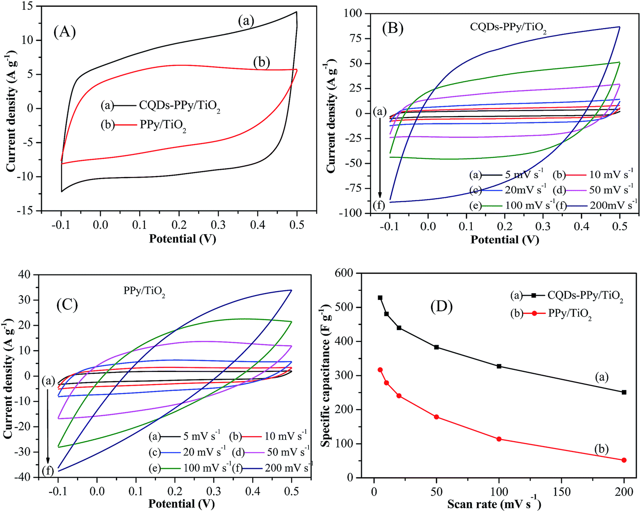
Cyclic voltammetry measurements were carried out to evaluate the modification effect of CQDs on the electrochemical performance of PPy. Fig. 6(A) shows CV curves of CQDs–PPy/TiO2 and the PPy/TiO2 nanotube hybrid at a scan rate of 20 mV s−1 in 1 M H2SO4 electrolyte solution with a potential range from −0.1 to 0.5 V. CV curves exhibited a quasi-rectangular shape and near mirror-image symmetry with respect to the zero-current line, demonstrating a capacitive behavior. The current density and the enclosed area of the CV curve of the CQDs–PPy/TiO2 nanotube hybrid was much larger than that of PPy/TiO2, revealing a higher electrical conductivity and capacitive performance. The specific capacitance is calculated using eqn (3) as follows:| |
 | (3) |
where ∫idν is the integrated area of the CV curves; m is the mass of the electroactive material in the electrode; ΔV is the scanned potential window and ν is the scan rate.
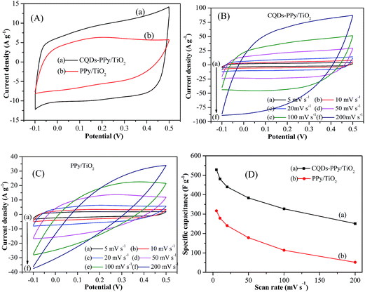 |
| | Fig. 6 (A) CV curves of CQDs–PPy/TiO2 and PPy/TiO2 nanotube hybrid in 1 M H2SO4 electrolyte solution at scan rate of 20 mV s−1; CV curves of (B) CQDs–PPy/TiO2 and (C) PPy/TiO2 nanotube hybrid at different scan rates; (D) corresponding specific capacitance in terms of CV scan rate. | |
The calculated specific capacitance was increased from 241 F g−1 for PPy/TiO2 to 440 F g−1 for the CQDs–PPy/TiO2 nanotube hybrid at a scan rate of 20 mV s−1. The enhanced capacitance performance of the CQDs–PPy/TiO2 nanotube hybrid was attributed to a positive synergistic effect between CQDs and PPy. The incorporation of CQDs into PPy could provide a conductive channel, rendering fast electron transfer in the CQDs–PPy/TiO2 nanotube hybrid.42
Fig. 6(B and C) shows the CV curves of CQDs–PPy/TiO2 and PPy/TiO2 nanotube hybrid at different scan rates. When the scan rate was increased from 5 to 200 mV s−1, the CV curve of the CQDs–PPy/TiO2 nanotube hybrid mostly kept a quasi-rectangular shape with small distortion, indicating good capacitive behavior for the CQDs–PPy/TiO2 nanotube hybrid. The proportionality of the peak current density with the scan rate implies that the CQDs–PPy/TiO2 nanotube hybrid had low ohmic resistance and good rate capabilities. Comparatively, the CV curves of PPy/TiO2 nanotube hybrid also exhibited a quasi-rectangular shape at low scan rates from 5 to 50 mV s−1, indicating its capacitive behavior. However, due to the low conductivity of PPy/TiO2, the shape of the CV curves gradually deviated from a typical rectangular shape when the scan rate was increased from 100 to 200 mV s−1, presenting more resistor element properties involved in the capacitor element. Fig. 6(D) shows the specific capacitance of CQDs–PPy/TiO2 and PPy/TiO2 nanotube hybrid in terms of CV scan rate. The specific capacitance of the CQDs–PPy/TiO2 nanotube hybrid decreased from 529 to 251 F g−1 when the scan rate was increased from 5 to 200 mV s−1, keeping 47.5% capacitance retention. Comparatively, the specific capacitance of the PPy/TiO2 nanotube hybrid dropped from 317 to 52 F g−1, representing only 16.4% capacitance retention. Accordingly, the CQDs–PPy/TiO2 had a higher capacitance and better rate capability than PPy/TiO2.
The scan rate plays an important role in the process of electron transfer and electrolyte ion diffusion into the electrode material. In general, the specific capacitance decreased with the increase of scan rate. At low scan rates, electrolyte ion diffusion becomes sufficient towards external surface and inner active sites of electrode material. More complete redox reaction usually contributes to a higher capacitance. At high scan rates, sufficient ion diffusion of electrolyte could delay the doping/dedoping process of PPy, resulting in a low capacitance. The inherent low electrical conductivity of bulk PPy causes high resistance for electron transfer. CQDs with superior electrical conductivity, number of carriers and charge carrier mobility pave the continuous electron transfer channels for CQDs–PPy/TiO2 nanotube hybrid. The presence of CQDs in bulk PPy promoted electron transfer from PPy to current collector during electrochemical reaction process, which ultimately improved current density and specific capacitance.27
3.6 Galvanostatic charge–discharge performance
Galvanostatic charge–discharge measurement was performed to further investigate the electrochemical capacitance performance of CQDs–PPy/TiO2 and PPy/TiO2 nanotube hybrid electrodes. The specific capacitance is calculated using eqn (4) as follows:| |
 | (4) |
where Cm is the specific capacitance, I is the current of charge–discharge, Δt is the discharge time, ΔV is the scanned potential window, and m is the mass of active material in the electrode.
Fig. 7(A) displays the GCD curves of CQDs–PPy/TiO2 and PPy/TiO2 nanotube hybrid electrodes at a current density of 0.5 A g−1. Both GCD curves exhibit the near triangle shapes, presenting a reversible and fast ion doping/dedoping PPy. The specific capacitance increased from 482 F g−1 (or 161 mF cm−2) for PPy/TiO2 to 849 F g−1 (or 212 mF cm−2) for CQDs–PPy/TiO2. CQDs in the hybrid material served as a conductive path for electron shuttling during the charge–discharge process. CQDs-hybridized PPy decreased the electron transfer resistance and interfacial contact resistance, which integratively promoted the electrochemical capacitance.
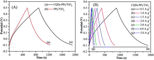 |
| | Fig. 7 (A) GCD curves of CQDs–PPy/TiO2 and PPy/TiO2 nanotube hybrid at 0.5 A g−1 in 1 M H2SO4 electrolyte solution; (B) GCD curves of CQDs–PPy/TiO2 at a current density of 0.5–5.0 A g−1. | |
In addition, voltage drop across internal resistance (IR drop) was observed with the initial discharge curves. IR drop roughly reflects the internal resistance of the electrode materials. It involves electronic resistance related to electroactive materials and ionic resistance related to electrolyte conductivity and ion mobility. IR drop was 2.1 mV and 16.8 mV for CQDs–PPy/TiO2 and PPy/TiO2 nanotube hybrid, demonstrating the superior electrical conductivity of CQDs–PPy/TiO2. The negligible IR drop of CQDs–PPy/TiO2 nanotube hybrid indicated its high electrical conductivity of CQDs–PPy. Obvious IR drop of PPy/TiO2 nanotube hybrid was ascribed to the large internal resistance of PPy. Fig. 7(B) shows the GCD curves of CQDs–PPy/TiO2 nanotube hybrid electrode at different current densities from 0.5 to 5 A g−1. At low current densities of 0.5 and 1 A g−1, the GCD curves were straight and had a very symmetric nature, suggesting a good reversibility and good coulombic efficiency during GCD processes. When increasing the current density from 1.5 and 5 A g−1, a small IR drop was observed on the initial discharge curves. However, GCD curves were still symmetrical, indicating a reversible electrochemical behavior. The specific capacitance of the CQDs–PPy/TiO2 nanotube hybrid dropped from 849 to 533 F g−1 (also 212 to 133 mF cm−2) when the current density was increased from 0.5 to 5 A g−1, indicating a good capacitance retention of 62.8%. Such capacitance is comparable to or even higher than the reported results. For instance, Dhibar et al. fabricated a silver–polyaniline/multiwalled carbon nanotubes nanocomposite and reported the highest specific capacitance of 528 F g−1 at a 5 mV s−1 scan rate in 1 M KCl solution.28 Wei et al. deposited polypyrrole–silver composites on a nickel foam via the redox reaction between pyrrole and silver nitrate and reported the highest specific capacitance of 493 F g−1 in 0.5 M K2SO4 electrolyte at a current density of 1 A g−1.29
Good long-term cycle stability is required for supercapacitor applications. Fig. 8(A and B) show the cycling stability of CQDs–PPy/TiO2 and PPy/TiO2 nanotube hybrid at a high current density of 20 A g−1 for 2000 cycles. The specific capacitance of the CQDs–PPy/TiO2 nanotube hybrid decreased from 317 to 283 F g−1 (also 79.3 to 70.8 mF cm−2), presenting an 89.3% retention capacity. Comparatively, the specific capacitances of the PPy/TiO2 nanotube hybrid decreased from 107 to 84 F g−1 (also 35.7 to 28.1 mF cm−2), presenting a 78.5% retention capacity. The inset image of Fig. 8(A and B) reveals the CQDs–PPy/TiO2 and PPy/TiO2 nanotube hybrid with 100 charge–discharge cycles at different current densities. The capacitance decay of the CQDs–PPy/TiO2 nanotube hybrid at a current density of 2, 4, 6, 8 and 10 A g−1 was 0.5%, 0.66%, 1%, 0.85% and 2.1%, respectively. Comparatively, the capacitance decay of the PPy/TiO2 nanotube hybrid at current densities of 2, 4, 6, 8 and 10 A g−1 was 1%, 2.5%, 2.3%, 1.1% and 2.8%, respectively. The CQDs–PPy/TiO2 nanotube hybrid exhibited slightly better rate capability. Usually, PPy-based electrode material usually suffers from poor cycling stability because the swelling and shrinking of PPy could lead to polymer degradation. However, the CQDs–PPy/TiO2 exhibited good cycling stability when CQDs was incorporated into PPy. CQDs provided a robust support for PPy, thus enhancing the mechanical strength and preventing PPy from severely swelling and shrinking during the cycling charge–discharge process. Therefore, the CQDs–PPy/TiO2 nanotube hybrid exhibited a better stability than the PPy/TiO2 nanotube hybrid.
 |
| | Fig. 8 (A and B) Galvanostatic charge–discharge cycling stability of CQDs–PPy/TiO2 and PPy/TiO2 nanotube hybrid at a current density of 20 A g−1 for 2000 cycles. The inset in (A and B) shows the cycling stability of CQDs–PPy/TiO2 and PPy/TiO2 nanotube array electrodes at different current density; (C) Ragone plots of the CQDs–PPy/TiO2 nanotube hybrid. | |
In addition, the energy density and the power density are also important parameters to evaluate the energy storage of supercapacitor electrode materials. They can be calculated using the following eqn (5) and (6):
| |
 | (5) |
| |
 | (6) |
where
E is the energy density,
P is the power density,
I is the current of charge–discharge, Δ
t is the discharge time, Δ
V is the scanned potential window, and
m is the mass of active material in the electrode.
Fig. 8(C) shows the Ragone plot (power density vs. energy density) of the CQDs–PPy/TiO2 nanotube hybrid calculated from GCD curves. The CQDs–PPy/TiO2 nanotube hybrid exhibited an energy density of 42.5 W h kg−1 at a power density of 150 W kg−1, whereas it still maintained a 26.5 W h kg−1 capacity at a high power density of 1500 W kg−1. The CQDs–PPy/TiO2 nanotube hybrid electrode with a high energy density suggests its unique capability to meet the requirement for high capacitance and long cycling life. The uniform ordered structure of the CQDs–PPy nanohybrid provided a highly accessible electrochemical surface for utilizing the full active sites of PPy. The effective incorporation CQDs into PPy could simultaneously increase electrochemical capacitance and cycle stability of PPy, leading to a superior electrochemical performance.
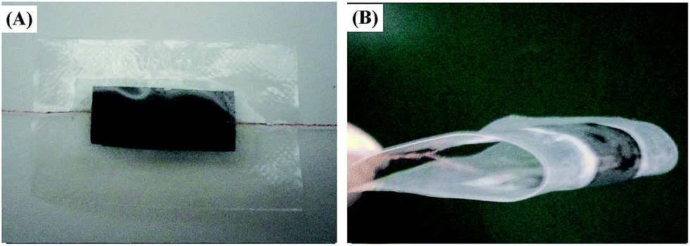
3.7 Flexible all-solid-state supercapacitor
A flexible solid-state supercapacitor was also investigated using the CQDs–PPy nanohybrid, which was fabricated by removing the TiO2 template from the CQDs–PPy/TiO2. Fig. 9 shows images of a flexible CQDs–PPy supercapacitor in both planar and bent state. As-fabricated, the CQDs–PPy supercapacitor had total area of 13 cm × 30 mm and a total thickness of 0.6 mm. The supercapacitor could be fully folded to 180° and achieve a stable charge–discharge process, demonstrating the good flexibility of this supercapacitor.
 |
| | Fig. 9 Images of flexible CQDs–PPy supercapacitor in (A) planar state and (B) bent state. | |
The electrochemical performance of the CQDs–PPy supercapacitor was also investigated. Fig. 10(A) shows the CV curves of CQDs–PPy supercapacitor at a scan rate of 20 mV s−1 when this supercapacitor keeps at a planar state and bent state. The CQDs–PPy supercapacitor exhibited the similar capacitance performance by comparing the integral areas of CV curves. The corresponding specific capacitance was estimated to be 5.92 and 6.09 F g−1, confirming an excellent mechanical stability and flexibility of this CQDs–PPy supercapacitor. Fig. 10(B) shows CV curves of the CQDs–PPy supercapacitor at different current densities. The shape of the CV curves indicates the characteristic supercapacitor behavior. The specific capacitance decreased from 20 to 1.1 F g−1 when the scan rate was increased from 5 to 200 mV s−1. Such a capacitance decrease along with increasing scan rate is attributed to the inner active sites in the gel electrolyte not being able to sustain fast redox transitions at high scan rates.
 |
| | Fig. 10 CV curves of flexible CQDs–PPy supercapacitor (A) at a planar state and bent state, (B) at different scan rates. | |
Fig. 11 displays a GCD curve for a flexible CQDs–PPy supercapacitor in a potential window from −0.6 to 0.6 V. The shape of the GCD curve indicates the dominant contribution of pseudocapacitance. Obvious IR drop revealed the larger ohmic internal resistance using a gel electrolyte rather than an aqueous electrolyte. On the other hand, the potential window of the CQDs–PPy all-solid-state supercapacitor had been obviously increased. The specific capacitances of CQDs–PPy supercapacitor was 14.5 F g−1 at a current density of 0.02 A g−1. This flexible CQDs–PPy supercapacitor exhibited much higher capacitance than our previously reported flexible PPy supercapacitor, which was 13 F g−1 at low current density of 0.005 A g−1.9 It demonstrates a high possibility for this CQDs–PPy supercapacitor to be used for flexible electronic devices in the future.
 |
| | Fig. 11 GCD curve of flexible CQDs–PPy supercapacitor at a current density of 0.02 A g−1. | |
4. Conclusions
A CQDs–PPy/TiO2 nanotube hybrid was fabricated as a supercapacitor electrode material by the controlled electrochemical synthesis route. The CQDs–PPy/TiO2 nanotube hybrid presented a highly ordered and heterogeneous coaxial nanotube structure. CQDs hybridizing modification could improve the electrical conductivity of PPy. The charge transfer resistance decreased from 22.4 mΩ cm−2 to 9.3 mΩ cm−2 and the ohmic resistance decreased from 0.817 to 0.154 Ω cm−2 when PPy/TiO2 was converted into the CQDs–PPy/TiO2 nanotube hybrid. The specific capacitance was promoted from 482 F g−1 (or 161 mF cm−2) for PPy/TiO2 to 849 F g−1 (or 212 mF cm−2) for CQDs–PPy/TiO2 in 1.0 M H2SO4 electrolyte solution at a current density of 0.5 A g−1. The capacitance retention was slightly increased from 78.5% to 89.3% after 2000 cycles at a high current density of 20 A g−1. The flexible all-solid-state supercapacitor based on a CQDs–PPy nanohybrid electrode and PVA/H2SO4 gel electrolyte exhibited a specific capacitance of 14.5 F g−1 at a current density of 0.02 A g−1 and stable capacitive performance at planar and bent state. The effective incorporation CQDs into PPy could simultaneously increase electrochemical capacitance and cycle stability of PPy, leading to a superior electrochemical performance. CQDs-hybridized PPy is promising for applications as a supercapacitor electrode material for energy storage.
Acknowledgements
The study was supported by the National Natural Science Foundation of China (No. 21373047 and 20871029), the Program for New Century Excellent Talents in University of the State Ministry of Education (No. NCET-08-0119), and the Science & Technology Program of Suzhou City (No. ZXG2012026, SYN201208, SYG201017).
Notes and references
- Y. J. Peng, T. H. Wu, C. T. Hsu, S. M. Li, M. G. Chen and C. C. Hu, J. Power Sources, 2014, 272, 970 CrossRef CAS PubMed.
- H. Mudila, V. Joshi, S. Rana, M. G. H. Zaidi and S. Alam, Carbon Letters, 2014, 15, 171 CrossRef.
- Y. Xie, H. Du and C. Xia, Microporous Mesoporous Mater., 2015, 204, 163 CrossRef CAS PubMed.
- Y. Xie, C. Xia, H. Du and W. Wang, J. Power Sources, 2015, 286, 561 CrossRef CAS PubMed.
- C. Xia, Y. Xie, H. Du and W. Wang, J. Nanopart. Res., 2015, 17, 30 CrossRef.
- C. Xia, Y. Xie, W. Wang and H. Du, Synth. Met., 2014, 192, 93 CrossRef CAS PubMed.
- W. H. Sun, Z. L. Mo, H. L. Li, Y. Sun and Y. Q. Zhou, Polym. Eng. Sci., 2014, 54, 2731 CAS.
- H. Du, Y. Xie, C. Xia, W. Wang and F. Tian, New J. Chem., 2014, 38, 1284 RSC.
- H. Du, Y. Xie, C. Xia, W. Wang, F. Tian and Y. Zhou, Mater. Lett., 2014, 132, 417 CrossRef CAS PubMed.
- Y. Xie, D. Wang, Y. Zhou, H. Du and C. Xia, Synth. Met., 2014, 198, 59 CrossRef CAS PubMed.
- S. B. Ye and J. C. Feng, ACS Appl. Mater. Interfaces, 2014, 6, 9671 CAS.
- Y. Xie and Y. Zhan, J. Porous Mater., 2015, 22, 403 CrossRef CAS.
- A. H. P. de Oliveira and H. P. de Oliveira, J. Power Sources, 2014, 268, 45 CrossRef CAS PubMed.
- Y. Xie and W. Wang, J. Chem. Technol. Biotechnol., 2015 DOI:10.1002/jctb.4737.
- W. Wang, Y. Xie, Y. Wang, H. Du, C. Xia and F. Tian, Microchim. Acta, 2014, 181, 381 CrossRef CAS.
- Y. Xie and H. Du, J. Solid State Electrochem., 2012, 16, 2683 CrossRef CAS.
- W. Khoh and J. Hong, Colloids Surf., A, 2014, 456, 26 CrossRef CAS PubMed.
- Y. Xie and X. Fang, Electrochim. Acta, 2014, 120, 273 CrossRef CAS PubMed.
- F. Tian, Y. Xie, H. Du, Y. Zhou, C. Xia and W. Wang, RSC Adv., 2014, 4, 41856 RSC.
- Y. Xie, F. Song, C. Xia and H. Du, New J. Chem., 2015, 39, 604 RSC.
- Y. Xie, Y. Wang and H. Du, Mater. Sci. Eng., B, 2013, 178, 1443 CrossRef CAS PubMed.
- K. B. Xu, X. J. Huang, Q. Liu, R. J. Zou, W. Y. Li, X. J. Liu, S. J. Li, J. M. Yang and J. Q. Hu, J. Mater. Chem. A, 2014, 2, 16731 CAS.
- H. H. Zhou, G. Y. Han, Y. M. Xiao, Y. Z. Chang and H. J. Zhai, J. Power Sources, 2014, 263, 259 CrossRef CAS PubMed.
- Y. Xie and Y. Meng, RSC Adv., 2014, 4, 41734 RSC.
- Y. Xie, Y. Jin, Y. Zhou and Y. Wang, Appl. Surf. Sci., 2014, 313, 549 CrossRef CAS PubMed.
- W. Wang, Y. Xie, C. Xia, H. Du and F. Tian, Microchim. Acta, 2014, 181, 1325 CrossRef CAS.
- D. S. Patil, S. A. Pawar, R. S. Devan, M. G. Gang, Y. R. Ma, J. H. Kim and P. S. Patil, Electrochim. Acta, 2013, 105, 569 CrossRef CAS PubMed.
- S. Dhibar and C. K. Das, Ind. Eng. Chem. Res., 2014, 53, 3495 CrossRef CAS.
- J. T. Wei, G. Z. Xing, L. Gao, H. Suo, X. P. He, C. Zhao, S. Li and S. X. Xing, New J. Chem., 2013, 37, 337 RSC.
- S. Chen and I. Zhitomirsky, Mater. Lett., 2014, 135, 47 CrossRef CAS PubMed.
- X. Wu, X. Hong, Z. Luo, K. S. Hui, H. Chen, J. Wu, K. N. Hui, L. Li, J. Nan and Q. Zhang, Electrochim. Acta, 2013, 89, 400 CrossRef CAS PubMed.
- B. Andres, S. Forsberg, A. Paola Vilches, R. Zhang, H. Andersson, M. Hummelgård, J. Bäckström and H. Olin, Nord. Pulp Pap. Res. J., 2012, 27, 481 CAS.
- X. F. Chen, W. X. Zhang, Q. J. Wang and J. Y. Fan, Carbon, 2014, 79, 165 CrossRef CAS PubMed.
- Q. L. Zhao, Z. L. Zhang, B. H. Huang, J. Peng, M. Zhang and D. W. Pang, Chem. Commun., 2008, 5116 RSC.
- L. Wang, Y. L. Wang, T. Xu, H. B. Liao, C. J. Yao, Y. Liu, Z. Li, Z. W. Chen, D. Y. Pan, L. T. Sun and M. H. Wu, Nat. Commun., 2014, 5, 6357 Search PubMed.
- Y. K. Lee, K. J. Lee, D. S. Kim, D. J. Lee and J. Y. Kim, Synth. Met., 2010, 160, 814 CrossRef CAS PubMed.
- S. Bose, T. Kuila, M. E. Uddin, N. H. Kim, A. K. T. Lau and J. H. Lee, Polym. J., 2010, 51, 5921 CAS.
- A. M. Dhirde, N. V. Dale, H. Salehfar, M. D. Mann and T. H. Han, IEEE Trans. Energ. Convers., 2010, 25, 778 CrossRef.
- R. F. Li, Z. G. Li, Y. Y. Zhu and K. Qi, J. Alloys Compd., 2013, 580, 327 CrossRef CAS PubMed.
- W. J. Kuang, J. A. Mathews, M. L. Taylor and D. D. Macdonald, Electrochim. Acta, 2014, 136, 493 CrossRef CAS PubMed.
- C. Xia, Y. Xie, Y. Wang, W. Wang, H. Du and F. Tian, J. Appl. Electrochem., 2013, 43, 1225 CrossRef CAS.
- Y. S. Lim, Y. P. Tan, H. N. Lim, N. M. Huang, W. T. Tan, M. A. Yarmo and C. Y. Yin, Ceram. Int., 2014, 40, 3855 CrossRef CAS PubMed.
|
| This journal is © The Royal Society of Chemistry 2015 |
Click here to see how this site uses Cookies. View our privacy policy here.