Amorphous CoFe(OH)x hollow hierarchical structure: an efficient and durable electrocatalyst for oxygen evolution reaction†
Xiaoyang
Yue
a,
Wentao
Ke
a,
Minghua
Xie
 b,
Xiaoping
Shen
 *a,
Zhenyu
Yan
a,
Zhenyuan
Ji
a,
Guoxing
Zhu
a,
Keqiang
Xu
a and
Hu
Zhou
c
aSchool of Chemistry and Chemical Engineering, Jiangsu University, Zhenjiang 212013, P. R. China. E-mail: xiaopingshen@163.com
bKey Laboratory for Advanced Technology in Environmental Protection of Jiangsu Province, Yancheng Institute of Technology, Yancheng 224051, P. R. China
cSchool of Environmental and Chemical Engineering, Jiangsu University of Science and Technology, Zhenjiang 212003, P. R. China
First published on 22nd November 2019
Abstract
Developing novel earth-abundant electrocatalysts with highly efficient and durable activity for the oxygen evolution reaction (OER) is in great demand in the clean hydrogen production. Herein, an amorphous mixed cobalt–iron hydroxide (CoFe(OH)x) with a uniform hollow hierarchical structure is exploited and applied in the OER. The amorphous structure can supply abundant defects and reaction sites, and the hollow hierarchical microspheres with numerous vertically grown nanosheets on the shell can provide sufficient contact between electrolyte and active species, thus exposing abundant accessible active sites for electrocatalysis. As a result, the as-prepared CoFe(OH)x exhibits a superior electrocatalytic OER activity in alkaline medium with a low overpotential of 293 mV at a current density of 10 mA cm−2 and a small Tafel slope of 67.4 mV dec−1. CoFe(OH)x also shows significantly enhanced OER activity compared to Co(OH)2 owing to its optimized electronic structure and conductivity tuned by the introduction of Fe. The turnover frequency of CoFe(OH)x (55.7 × 10⁻³ s−1) is 8.8 times larger than that of Co(OH)2 (6.3 × 10⁻³ s−1). This work paves a way for rational design of hollow structured bimetal hydroxides with enhanced electrocatalytic performance.
1. Introduction
Electrocatalytic water splitting is an effective and artificially controllable way to obtain clean and sustainable hydrogen energy, which is considered as one of the most promising alternatives to traditional fossil fuels.1,2 However, due to the sluggish reaction kinetics caused by the multi-electron transfer process and the oxygen–oxygen bond formation, the oxygen evolution reaction (OER) has been regarded as the bottleneck of water splitting systems.3 Currently, the noble metal oxide RuO2 is used as a commercial OER catalyst because of its high performance. However, its limited reserves and high cost make it unfavorable for large-scale application.4,5 From this perspective, the development of non-precious metal alternatives with earth-abundant elements is highly desirable and imperative. In recent years, extensive endeavors have been devoted to development of transition metal-based catalysts, especially Co, Ni, and Fe-based catalysts, usually in the forms of metal oxides, metal (oxy)hydroxides, metal sulfides, metal borides and metal phosphides or phosphates.6–11 Although some significant progress has been achieved, the construction of highly efficient and durable OER catalysts with earth-abundant elements still remains a great challenge.12 Generally speaking, Fe, Co and Ni-based electrocatalysts with only a single metal usually encounter severe agglomeration, corrosion of the active metal component and leaching of anions (i.e. S and P) during the preparation or electrocatalytic course.13 To address these issues, a lot of efforts have been made on the rational design of multi-metal catalysts from the viewpoints of their enhanced conductivity, stability, and synergistic effect between different metals by simply adjusting elemental doping or chemical composition.14,15 Recent work has demonstrated that a superior activity toward the OER can be achieved from bimetal materials as compared to their single metal counterparts.16 It is acknowledged that the presence of a bimetal center is likely to lower the thermodynamic barrier during proton-coupled electron transfer pre-equilibrium and boost the formation of O–O bonds.17 Though it still remains vague to identify the catalytically active sites for bimetallic or multi-metal catalysts, the formation of metal species with higher valence and their effects under oxidative conditions are clear, which is also crucial to expediting the OER.18 Yan et al.19 exploited multiple 2D atomic-thick bimetal nanosheets and provided a detailed understanding of the electronic structures of layered double hydroxide (LDH) nanostructures from a theoretical perspective, verifying the high electron conductivity of Co- and Fe-based LDHs for the OER process.Currently, metal electrocatalysts with amorphous crystal structures are attracting special attention due to their superior electrochemical properties over their crystalline counterparts.20,21 It is believed that amorphous materials can provide more electrochemically active sites or defect sites than their crystal counterparts, which can significantly enhance the electrocatalytic performance. In addition, amorphous materials usually possess extraordinary structural stability and strong corrosion resistance, thus achieving robust cycling stability under harsh operating environments.22–24 Furthermore, intrinsic properties such as the superhydrophilic nature, and even the underwater superaerophobic nature, can be achieved by construction of an amorphous structure, which can directly accelerate the bubble nucleation and release in the OER process.25 For instance, Gao et al.22 reported an amorphous mixed-metal (Ni–Fe) hydroxide with high durability under a continuous long-term operation test for over 24 hours. Balram et al.20 reported an amorphous α-phase mixed nickel–cobalt hydroxide with a superhydrophilic nature, delivering a low overpotential of 255 mV to achieve a current density of 10 mA cm−2. Besides, electrocatalytic materials with expected morphologies or structures are also crucial to the catalytic activity.26,27 The relationship between the structures and properties of these nanomaterials has become one of the central issues in the scientific community. Electrocatalytic materials with various morphologies have been developed in recent years, such as the needle-like morphology, nanosheets and hollow structures.28–31 Among them, hollow or cage-like structures with thin shells, large inner cavities and tailored compositions have attracted growing interest owing to their low density, high permeability and large specific surface area, which can promote intimate contact between active species and electrolyte species, thus maximizing catalyst accessibility.32,33
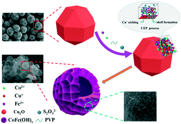
In this paper, an efficient and robust bimetal hydroxide catalyst, amorphous CoFe(OH)x hollow hierarchical microspheres, was successfully fabricated via a template-assisted route inspired by Pearson's principle with Cu2O polyhedra as the sacrificial template (Scheme 1). The as-synthesized CoFe(OH)x delivers an overpotential as low as 293 mV at a current density of 10 mA cm−2 with a Tafel value of 67.4 mV dec−1 in 1.0 M KOH, which outshines the commercial precious metal RuO2 catalyst and most of the metal hydroxide electrocatalysts reported so far. Impressively, the electrocatalytic activity exhibits even a little improvement after a long-term stability test, indicating an outstanding durability. Furthermore, it is verified that there exists a synergistic interaction between Co2+ and Fe3+, and the electronic structure of CoFe(OH)x can be tuned by introducing an appropriate amount of Fe while maintaining its hollow hierarchical structure.
2. Experimental
2.1. Materials
CoCl2·6H2O (A.R.), CuCl2·2H2O (A.R.), FeCl3·6H2O (A.R.), Na2S2O3·7H2O (A.R.), ascorbic acid (A.R.), NaOH (A.R.), KOH (A.R.) and polyvinyl pyrrolidone (PVP, G.R.) were purchased from Sinopharm Chemical Reagent Co. Ltd. Commercial RuO2 (A.R.) was purchased from Alfa Aesar Chemical Co. Ltd., China. All the chemicals in the experiment were used as initially received. Deionized (DI) water was used throughout the experiments.2.2. Syntheses
![[thin space (1/6-em)]](https://www.rsc.org/images/entities/char_2009.gif) :
:![[thin space (1/6-em)]](https://www.rsc.org/images/entities/char_2009.gif) 1) to form a uniform Cu2O dispersion by ultrasonication, into which a certain amount of PVP was added, followed by the addition of CoCl2·6H2O and FeCl3·6H2O. The mixture was stirred at room temperature for 30 min. After that, 50 mL of 1 M Na2S2O3 aqueous solution was added dropwise. Then the reaction was continued until the brick red color thoroughly disappeared. Eventually, CoFe(OH)x hollow microspheres were successfully fabricated. The as-obtained products were labeled CoFe(OH)x-1, CoFe(OH)x-2 and CoFe(OH)x-3 for different molar ratios of Co to Fe of 9.5
1) to form a uniform Cu2O dispersion by ultrasonication, into which a certain amount of PVP was added, followed by the addition of CoCl2·6H2O and FeCl3·6H2O. The mixture was stirred at room temperature for 30 min. After that, 50 mL of 1 M Na2S2O3 aqueous solution was added dropwise. Then the reaction was continued until the brick red color thoroughly disappeared. Eventually, CoFe(OH)x hollow microspheres were successfully fabricated. The as-obtained products were labeled CoFe(OH)x-1, CoFe(OH)x-2 and CoFe(OH)x-3 for different molar ratios of Co to Fe of 9.5![[thin space (1/6-em)]](https://www.rsc.org/images/entities/char_2009.gif) :
:![[thin space (1/6-em)]](https://www.rsc.org/images/entities/char_2009.gif) 0.5, 9
0.5, 9![[thin space (1/6-em)]](https://www.rsc.org/images/entities/char_2009.gif) :
:![[thin space (1/6-em)]](https://www.rsc.org/images/entities/char_2009.gif) 1 and 8
1 and 8![[thin space (1/6-em)]](https://www.rsc.org/images/entities/char_2009.gif) :
:![[thin space (1/6-em)]](https://www.rsc.org/images/entities/char_2009.gif) 2, respectively. For comparison, Co(OH)2 hollow microspheres were also synthesized by the same method but without the addition of FeCl3·6H2O. Besides, p-Co(OH)2 was also synthesized by the precipitation method via directly mixing CoCl2·6H2O and KOH solution.
2, respectively. For comparison, Co(OH)2 hollow microspheres were also synthesized by the same method but without the addition of FeCl3·6H2O. Besides, p-Co(OH)2 was also synthesized by the precipitation method via directly mixing CoCl2·6H2O and KOH solution.
2.3. Electrochemical measurements
All electrochemical measurements were carried out on a CHI 760E electrochemical analyzer with 1 M KOH as an electrolyte in a three-electrode system, in which a carbon rod was used as the counter electrode, an Ag/AgCl electrode filled with saturated KCl solution as the reference electrode and a polished glassy carbon rotating disk electrode (GCE, d = 5 mm) covered with the active material as the working electrode. To obtain uniform catalyst inks, 2 mg of the ground sample was dispersed in a mixed solution consisting of 10 μL of Nafion solution and 490 μL of ethanol, followed by sonication for 30 min. Immediately after polishing the GCE, 15.0 μL of the solution was drop cast and naturally dried. Polarization curves were recorded by linear sweep voltammetry (LSV) at a scan rate of 5 mV s−1 with 95% IR compensation. Electrochemical impedance spectroscopy (EIS) was studied in a frequency range from 105 to 0.1 Hz. Potentials are referenced to the reversible hydrogen electrode (RHE) through the following calculation:| ERHE = EAg/AgCl + 0.059 pH + EθAg/AgCl |
The turnover frequency (TOF), mass activity and specific activity are obtained according to the following equations:35,36
| TOF = jS/(4Fn); |
| Mass Activity = j/m; |
| Specific Activity = j/(10m SBET); |
![[thin space (1/6-em)]](https://www.rsc.org/images/entities/char_2009.gif) 485 C mol−1) is the Faraday constant, the number 4 means 4 electrons per O2 molecule, and n is the molar number of metal ions calculated from the catalyst loading density. Assuming that all the Co and Fe ions in the catalysts are catalytically active and accessible for catalyzing the OER, TOF values, strictly speaking the lowest TOF values, were obtained from the above formula.
485 C mol−1) is the Faraday constant, the number 4 means 4 electrons per O2 molecule, and n is the molar number of metal ions calculated from the catalyst loading density. Assuming that all the Co and Fe ions in the catalysts are catalytically active and accessible for catalyzing the OER, TOF values, strictly speaking the lowest TOF values, were obtained from the above formula.
2.4. Instrumentation and characterization
The phase structures of the as-synthesized samples were examined by X-ray diffraction (XRD, Bruker D8 ADVANCE) at a scanning rate of 7° min−1 with Cu-Kα radiation (λ = 1.5406 Å). The Brunauer–Emmett–Teller (BET) surface area was determined at 77 K using a Micromeritics ASAP 2020 apparatus. The X-ray photoelectron spectroscopy (XPS) measurements were performed on a Thermo ESCALAB 250XI spectrometer. Scanning electron microscopy (SEM, JSM-6480) and transmission electron microscopy (TEM, JEM-2100) were used to observe the morphologies and microstructures of the as-prepared samples. Elemental analysis was conducted on an elemental analyzer (FLASH1112A), and the contents of metal ions in the composites were determined using an inductively coupled plasma optical emission spectrometer (ICP-OES, Vista-MPX).3. Results and discussion
3.1. Synthesis and characterization
As depicted in Scheme 1, by employing Na2S2O3 as the coordinating etchant, the Cu2O polyhedral template can be gradually etched because of the much stronger affinity between Cu+ and S2O32− than that between Cu+ and O2− within Cu2O. Meanwhile, OH− will be continuously generated, and then combines with Co2+ and Fe3+ around the etching interface to form the corresponding metal hydroxides. It should be mentioned that the hydrolysis of S2O32− also plays a certain role in promoting the formation of metal hydroxides. In fact, to obtain well-defined and high-quality products, it is necessary to introduce PVP and a non-aqueous solvent of ethanol into the reaction system, which can significantly restrain the release of OH−, and thus lower the etching rate of Cu2O. Through the coordinating etching and precipitation processes, the CoFe(OH)x hollow microspheres with an amorphous structure were formed. The related reactions are listed below:29| Cu2O + xS2O32− + H2O → [Cu2(S2O32−)x]2−2x + 2OH− | (1) |
| S2O32− + H2O ⇌ HS2O3− + OH− | (2) |
| Co2+ + Fe3+ + xOH− → CoFe(OH)x | (3) |
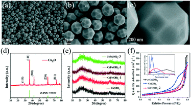
As shown in Fig. 1a–c, the as-synthesized Cu2O exhibits a well-defined polyhedral morphology with a size of ca. 1.5 μm. All the diffraction peaks of the XRD pattern (Fig. 1d) can be well indexed to cuprite phase Cu2O (JCPDS, No. 77-0199).34 The CoFe(OH)x hollow microspheres with an amorphous structure were obtained through coordinating etching of the Cu2O template, as revealed by the XRD patterns in Fig. 1e. The specific surface areas and porosity of the as-prepared samples were investigated by nitrogen adsorption–desorption (Fig. 1f). The specific surface areas of CoFe(OH)x-2, Co(OH)2 and p-Co(OH)2 are 92.8, 122.2 and 82.7 m2 g−1, respectively. The smaller specific surface area of CoFe(OH)x-2 than that of Co(OH)2 is probably due to the bigger average pore size after the introduction of Fe. The average pore diameter of CoFe(OH)x-2 is 14.6 nm, which is much larger than that of Co(OH)2 (9.6 nm). The much larger specific surface area of Co(OH)2 than p-Co(OH)2 can be ascribed to its hollow structure, which is favorable for boosting the contact area between the electrolyte and active species and more exposed active sites.
The morphology and microstructure of the as-synthesized samples were investigated by SEM and TEM. As shown in Fig. 2, for CoFe(OH)x-2, the uniform hollow quasi-spherical structure with vertically grown nanosheets on the shell was obtained with Cu2O polyhedra as the template. The morphology of the polyhedral template can be inherited by CoFe(OH)x-2, as revealed by the particles with some obvious angularities. The formation of the quasi-spherical structure can be attributed to the overgrowth of metal hydroxides on the template surface. The hollow structure has an average particle size of ca. 1.6 μm and a shell thickness of ca. 100 nm, and consists of numerous ultrathin nanosheets with a thickness of ca. 9 nm grown vertically on the shell, which endows the as-prepared CoFe(OH)x-2 with more exposed active sites. The corresponding elemental mapping images of Fe, Co and O with uniform distribution demonstrated the formation of mixed cobalt–iron hydroxide (Fig. 2d–j and S2†). Besides, it should be noted that there exist Cu, C and S elements, which could result from the residual Na2S2O3 etchant, PVP and [Cu2(S2O3)x]2−2x adsorbed on the sample.34 The actual contents of Co and Fe in CoFe(OH)x-2 were determined to be 45.12 wt% and 4.89 wt%, respectively, corresponding to the Co/Fe molar ratio of 8.74![[thin space (1/6-em)]](https://www.rsc.org/images/entities/char_2009.gif) :
:![[thin space (1/6-em)]](https://www.rsc.org/images/entities/char_2009.gif) 1, which is in good agreement with the feeding amounts of Co and Fe (9
1, which is in good agreement with the feeding amounts of Co and Fe (9![[thin space (1/6-em)]](https://www.rsc.org/images/entities/char_2009.gif) :
:![[thin space (1/6-em)]](https://www.rsc.org/images/entities/char_2009.gif) 1 in molar ratio) in the raw materials. The Co/Fe molar ratios of CoFe(OH)x-1, CoFe(OH)x-2 and CoFe(OH)x-3 are 16.65
1 in molar ratio) in the raw materials. The Co/Fe molar ratios of CoFe(OH)x-1, CoFe(OH)x-2 and CoFe(OH)x-3 are 16.65![[thin space (1/6-em)]](https://www.rsc.org/images/entities/char_2009.gif) :
:![[thin space (1/6-em)]](https://www.rsc.org/images/entities/char_2009.gif) 1, 8.74
1, 8.74![[thin space (1/6-em)]](https://www.rsc.org/images/entities/char_2009.gif) :
:![[thin space (1/6-em)]](https://www.rsc.org/images/entities/char_2009.gif) 1 and 3.80
1 and 3.80![[thin space (1/6-em)]](https://www.rsc.org/images/entities/char_2009.gif) :
:![[thin space (1/6-em)]](https://www.rsc.org/images/entities/char_2009.gif) 1, respectively (Table S1†). The samples of Co(OH)2 and CoFe(OH)x-1 also show similar hollow quasi-spherical structures with almost the same size of about 1.6 μm (Fig. S1†). However, CoFe(OH)x-3 shows severe agglomeration and collapse of the hollow structures, probably due to the introduction of a very high amount of Fe (Fig. S1e–f†), while p-Co(OH)2 synthesized by the precipitation method shows a sheet-like morphology (Fig. S3†).
1, respectively (Table S1†). The samples of Co(OH)2 and CoFe(OH)x-1 also show similar hollow quasi-spherical structures with almost the same size of about 1.6 μm (Fig. S1†). However, CoFe(OH)x-3 shows severe agglomeration and collapse of the hollow structures, probably due to the introduction of a very high amount of Fe (Fig. S1e–f†), while p-Co(OH)2 synthesized by the precipitation method shows a sheet-like morphology (Fig. S3†).
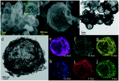 | ||
| Fig. 2 (a and b) SEM images and (c and d) TEM images of CoFe(OH)x-2, and (e–j) its elemental mapping images for Co, Fe, O, Cu, C and S. | ||
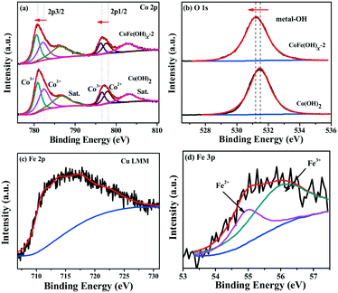
The surface composition and chemical states of CoFe(OH)x-2 and Co(OH)2 were investigated by XPS measurement. The full XPS spectra of CoFe(OH)x-2 and Co(OH)2 (Fig. S4†) reaffirm the expected elements in the two samples. Besides, the elements Cu, S and C were also detected for both samples, which is mainly due to their adsorption towards residual Na2S2O3, PVP and [Cu2(S2O3)x]2−2x, well consistent with the elemental mapping results (Fig. 2e–j). The high-resolution Co 2p3/2 spectrum of CoFe(OH)x-2 (Fig. 3a) yields two deconvoluted peaks at 780.6 and 782.1 eV with a satellite located at 786.3 eV, corresponding to Co3+ and Co2+, respectively, which has a little shift to lower binding energy compared to that of Co(OH)2. We infer that this phenomenon is mainly ascribed to the introduction of Fe in CoFe(OH)x-2. Fe with high valence can act as an electron withdrawing group towards the Co ions, thus weakening the binding force of Co ions to extra-nuclear electrons, correspondingly leading to the lower binding energy. The O 1s high-resolution spectra (Fig. 3b) of CoFe(OH)x-2 and Co(OH)2 exhibit a single peak at 531.2 eV and 531.5 eV, respectively, which represents metal–OH bonds. The shift to lower binding energy for metal–OH bonds in CoFe(OH)x-2 is favorable for the formation of intermediate catalytic metal species with high valence states such as CoOOH and FeOOH, which is necessary and indispensable for the OER.37,38 For the Fe 2p high-resolution spectrum (Fig. 3c), the peak cannot be accurately deconvoluted due to the overlapping Cu LMM Auger region.32 Therefore, the Fe 3p high-resolution spectrum was collected, which was deconvoluted into two peaks at 54.9 and 56.0 eV, corresponding to Fe2+ and Fe3+ (Fig. 3d). It is obvious that there exists a synergistic interaction among Co and Fe ions, which could tune the electronic structure of CoFe(OH)x for more efficient OER.
3.2. Electrocatalytic performance
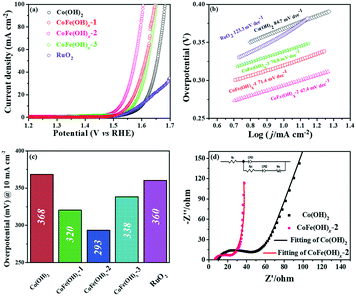
The electrocatalytic properties of the as-synthesized samples were systematically investigated in 1 M KOH solution with commercial RuO2 as the benchmark under identical test conditions. Among all the samples, CoFe(OH)x-2 exhibits the best OER catalytic performance, delivering an overpotential value of 293 mV at a current density of 10 mA cm−2, which is much lower than those of Co(OH)2 (368 mV) and commercial RuO2 (360 mV) (Fig. 4a and c). Therefore, the composition of the catalysts plays an essential role in their catalytic properties.18 In this study, with the increase in content of Fe, the OER catalytic performance of CoFe(OH)x firstly increases and then decreases (Fig. 4a and c), indicating that an appropriate proportion of Fe to Co is important for optimizing the electrocatalytic activity.39,40 It is worth noting that Co(OH)2 with a hollow structure exhibits a comparable electrocatalytic performance to commercial RuO2, while p-Co(OH)2 without a hollow structure presents a worse catalytic activity (390 mV) (Fig. S5†). Therefore, it is obvious that the unique hollow microstructure is conducive to improving the OER activity. To investigate the reaction kinetics, Tafel slopes were obtained by fitting the LSV curves with the Tafel formula η = b![[thin space (1/6-em)]](https://www.rsc.org/images/entities/char_2009.gif) log
log![[thin space (1/6-em)]](https://www.rsc.org/images/entities/char_2009.gif) j + a (where η (V) is the overpotential, j (mA cm−2) is the current density and b (mV dec−1) is the Tafel slope). In Fig. 4b, CoFe(OH)x-2 exhibits the smallest Tafel value of 67.4 mV dec−1, revealing its superior reaction kinetics compared to those of CoFe(OH)x-1 (71.4 mV dec−1), CoFe(OH)x-3 (70.0 mV dec−1), Co(OH)2 (84.7 mV dec−1) and commercial RuO2 (123.3 mV dec−1). The catalytic performance of CoFe(OH)x-2 is also comparable and even superior to those of the state-of-the-art Co, Fe, and Ni-based catalysts reported previously (Table S2†). It should be mentioned that for most of the catalysts, the electrocatalytic activity measured with a GCE is often much lower than those measured with Ni foam, Cu foam and other metal electrodes. It is widely acknowledged that the electrical conductivity of Co-based materials can be improved by the incorporation of Fe.19 As illustrated by the EIS measurement and fitted data shown in Fig. 4d, CoFe(OH)x-2 exhibits a lower Rct value of 16.83 Ω compared with pure Co(OH)2 (30.87 Ω), indicating that more efficient charge transfer can be achieved after the introduction of Fe, which results in the enhanced catalytic activity. Furthermore, the turnover frequency (TOF), mass activity and specific activity were also measured to evaluate the OER performances of the as-prepared samples.41,42 As shown in Table 1, CoFe(OH)x-2 reveals the highest TOF value of 55.7 × 10⁻³ s−1 at a given overpotential of 0.35 V, which is 8.8 times that of Co(OH)2-2 (6.3 × 10⁻³ s−1). Actually, not all the Co and Fe ions in the catalysts are catalytically active and accessible for stimulating the OER, and thus the TOF value obtained based on this calculation demonstrates the lowest one. Similarly, the mass activity and specific activity of CoFe(OH)x-2 were calculated to be 183.4 A g−1 and 0.198 mA cm−2, respectively, which are 8.9 and 11.6 times those of Co(OH)2. Considering the smaller specific surface area of CoFe(OH)x-2 than that of Co(OH)2, the much higher specific activity of CoFe(OH)x-2 demonstrates that the incorporation of Fe can largely facilitate the intrinsic electrocatalytic activity of Co(OH)2.
j + a (where η (V) is the overpotential, j (mA cm−2) is the current density and b (mV dec−1) is the Tafel slope). In Fig. 4b, CoFe(OH)x-2 exhibits the smallest Tafel value of 67.4 mV dec−1, revealing its superior reaction kinetics compared to those of CoFe(OH)x-1 (71.4 mV dec−1), CoFe(OH)x-3 (70.0 mV dec−1), Co(OH)2 (84.7 mV dec−1) and commercial RuO2 (123.3 mV dec−1). The catalytic performance of CoFe(OH)x-2 is also comparable and even superior to those of the state-of-the-art Co, Fe, and Ni-based catalysts reported previously (Table S2†). It should be mentioned that for most of the catalysts, the electrocatalytic activity measured with a GCE is often much lower than those measured with Ni foam, Cu foam and other metal electrodes. It is widely acknowledged that the electrical conductivity of Co-based materials can be improved by the incorporation of Fe.19 As illustrated by the EIS measurement and fitted data shown in Fig. 4d, CoFe(OH)x-2 exhibits a lower Rct value of 16.83 Ω compared with pure Co(OH)2 (30.87 Ω), indicating that more efficient charge transfer can be achieved after the introduction of Fe, which results in the enhanced catalytic activity. Furthermore, the turnover frequency (TOF), mass activity and specific activity were also measured to evaluate the OER performances of the as-prepared samples.41,42 As shown in Table 1, CoFe(OH)x-2 reveals the highest TOF value of 55.7 × 10⁻³ s−1 at a given overpotential of 0.35 V, which is 8.8 times that of Co(OH)2-2 (6.3 × 10⁻³ s−1). Actually, not all the Co and Fe ions in the catalysts are catalytically active and accessible for stimulating the OER, and thus the TOF value obtained based on this calculation demonstrates the lowest one. Similarly, the mass activity and specific activity of CoFe(OH)x-2 were calculated to be 183.4 A g−1 and 0.198 mA cm−2, respectively, which are 8.9 and 11.6 times those of Co(OH)2. Considering the smaller specific surface area of CoFe(OH)x-2 than that of Co(OH)2, the much higher specific activity of CoFe(OH)x-2 demonstrates that the incorporation of Fe can largely facilitate the intrinsic electrocatalytic activity of Co(OH)2.
| Catalysts | η 10 (mV) | Mass activity at η = 350 mV (A g−1) | Specific activity (mA cm−2) | TOF at η = 350 mV (s−1) |
|---|---|---|---|---|
| p-Co(OH)2 | 390 | 14.92 | 0.018 | 3.9 × 10⁻³ |
| Co(OH)2 | 368 | 20.56 | 0.017 | 6.3 × 10⁻³ |
| CoFe(OH)x-2 | 293 | 183.4 | 0.198 | 55.7 × 10⁻³ |
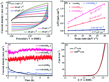
The electrochemically active specific surface area (ECSA) is a useful parameter to make an evaluation on the surface reactivity of the catalysts, which is proportional to the electric double layer capacitance (Cdl) according to the equation “ECSA = S × Cdl/Cs”,19,43 where S (0.196 cm2) is the surface area of the glassy carbon rotating disk electrode (d = 5 mm) and Cs is the capacitance of an atomically smooth planar surface of the material per unit area under identical electrolyte conditions. In an alkaline electrolyte, an average value of Cs = 0.040 mF cm−2 is used in this work based on previously reported Co-based OER catalysts.16 The Cdl values of these materials were determined from CV curves of the composites obtained at different sweep rates (5–30 mV s−1) in a potential window free of Faradaic processes (Fig. 5a and S6†). The Cdl values of CoFe(OH)x-1, CoFe(OH)x-2 and CoFe(OH)x-3 are 26.5 mF cm−2, 50.1 mF cm−2 and 3.06 mF cm−2, respectively, while the Cdl value of Co(OH)2 is only 2.57 mF cm−2. Therefore the corresponding ECSAs of CoFe(OH)x-1, CoFe(OH)x-2, CoFe(OH)x-3 and Co(OH)2 are obtained to be 129.8, 245.5, 15.0, and 12.6 cm2 (Fig. 5b). It is worth noting that the as-prepared CoFe(OH)x-2 exhibits the highest ECSA value, which is nearly 19.5 times that of pure Co(OH)2. The significantly improved active specific surface area of CoFe(OH)x-2 accounts for its extraordinary electrocatalytic performance, which can be mainly attributed to the tunable electronic structure by the introduction of Fe.44
The electrochemical stability of CoFe(OH)x-2 was evaluated by both a long-term test and cycling test. For the long-term test, it can be clearly seen that there is a continuous current decay for Co(OH)2. After incorporation of Fe, the current densities almost remained stable and even showed a little enhancement after 10 hours' operation, revealing that the introduction of Fe can effectively enhance the catalytic stability of Co(OH)2 (Fig. 5c). This improvement can be further confirmed by the long-term cycling test of CoFe(OH)x, which was performed at a scan speed of 100 mV s−1 between 1.0 and 1.53 V versus RHE in a 1.0 M KOH electrolyte. The LSV curve after 1000 CV cycles slightly shifts to lower potential compared to the initial one, demonstrating its enhanced electrocatalytic activity after the long-term cycling test (Fig. 5d).
4. Conclusion
In summary, we constructed an amorphous bimetal hydroxide electrocatalyst with a unique hollow and hierarchical structure via a simple template-assisted route. The amorphous structure provides abundant electrocatalytically active sites. Meanwhile, benefiting from its hollow structure with nanoporosity as well as numerous vertically grown nanosheets on the shell, sufficient contact between electrolyte species and active sites can be achieved, thus exposing abundant accessible active sites. Furthermore, the incorporation of Fe not only largely enhanced its intrinsic catalytic activity but also the long-term stability. Harvesting all these advantages, the as-prepared CoFe(OH)x-2 exhibits an excellent electrocatalytic OER activity in alkaline solution, requiring an overpotential as low as 293 mV to achieve a current density of 10 mA cm−2 and a small Tafel slope of 67.4 mV dec−1. This work paves an effective way for rational design of amorphous bimetal hydroxides with a hollow and hierarchical structure as efficient and durable electrocatalysts.Conflicts of interest
There are no conflicts to declare.Acknowledgements
We gratefully acknowledge financial support from the National Natural Science Foundation of China (No. 21875091 and 21776115), the Natural Science Foundation of Jiangsu Province (No. BK20171295 and BK20161343), and the Joint Open Fund of Jiangsu Collaborative Innovation Center for Ecological Building Material and Environmental Protection Equipments, and the Key Laboratory for Advanced Technology in Environmental Protection of Jiangsu Province (JH201804).Notes and references
- B. Obama, Science, 2017, 355, 126 CrossRef CAS PubMed
.
- G. Zhang, Y. S. Feng, W. T. Lu, D. He, C. Y. Wang, Y. K. Li, X. Y. Wang and F. F. Cao, ACS Catal., 2018, 8, 5431 CrossRef CAS
.
- T. Audichon, T. W. Napporn, K. B. Kokoh, C. Canaff, C. Comminges and K. B. Kokoh, J. Phys. Chem. C, 2016, 120, 2562 CrossRef CAS
.
- Y. J. Tang, H. J. Zhu, L. Z. Dong, A. M. Zhang, S. L. Li, J. Liu and Y. Q. Lan, Appl. Catal., B, 2019, 528 CrossRef CAS
.
- W. Ma, R. Ma, C. Wang, J. Liang, X. Liu, K. Zhou and T. Sasaki, ACS Nano, 2015, 9, 1977 CrossRef CAS PubMed
.
- H. Liang, F. Meng, M. Cabán-Acevedo, L. Li, A. Forticaux, L. Xiu, Z. Wang and S. Jin, Nano Lett., 2015, 15, 1421 CrossRef CAS PubMed
.
- J. M. V. Nsanzimana, V. Reddu, Y. Peng, Z. Huang, C. Wang and X. Wang, Chem. – Eur. J., 2018, 24, 18502 CrossRef CAS PubMed
.
- G. F. Chen, T. Y. Ma, Z. Q. Liu, N. Li, Y. Z. Su, K. Davey and S. Z. Qiao, Adv. Funct. Mater., 2016, 26, 3314 CrossRef CAS
.
- D. Das, S. Santra and K. K. Nanda, ACS Appl. Mater. Interfaces, 2018, 10, 35025 CrossRef CAS PubMed
.
- Y. Yang, K. Zhang, H. Lin, X. Li, H. C. Chan, L. Yang and Q. Gao, ACS Catal., 2017, 7, 2357 CrossRef CAS
.
- H. Zhang, X. Li, A. Hähnel, V. Naumann, C. Lin, S. Azimi, S. L. Schweizer, A. W. Maijenburg and R. B. Wehrspohn, Adv. Funct. Mater., 2018, 28, 1 Search PubMed
.
- T. Tang, W. J. Jiang, S. Niu, N. Liu, H. Luo, Q. Zhang, W. Wen, Y. Y. Chen, L. B. Huang, F. Gao and J. S. Hu, Adv. Funct. Mater., 2018, 28, 1 Search PubMed
.
- B. W. Zhang, Y. H. Lui, A. P. S. Gaur, B. L. Chen, X. H. Tang, Z. Y. Qi and S. Hu, ACS Appl. Mater. Interfaces, 2018, 10, 8739 CrossRef CAS PubMed
.
- M. Li, L. Tao, X. Xiao, X. Jiang, M. Wang and Y. Shen, ACS Sustainable Chem. Eng., 2019, 7, 4784 CrossRef CAS
.
- L. M. Cao, J. W. Wang, D. C. Zhong and T. B. Lu, J. Mater. Chem. A, 2018, 6, 3224 RSC
.
- P. Babar, A. Lokhande, H. H. Shin, B. Pawar, M. G. Gang, S. Pawar and J. H. Kim, Small, 2018, 14, 1 CrossRef PubMed
.
- D. Li, H. Baydoun, C. U. N. Verani and S. L. Brock, J. Am. Chem. Soc., 2016, 138, 4006 CrossRef CAS PubMed
.
- Y. Yang, L. Dang, M. J. Shearer, H. Sheng, W. Li, J. Chen, P. Xiao, Y. Zhang, R. J. Hamers and S. Jin, Adv. Energy Mater., 2018, 8, 1 Search PubMed
.
- R. Gao, H. Zhang and D. P. Yan, Nano Energy, 2017, 31, 90 CrossRef CAS
.
- A. Balram, H. Zhang and S. Santhanagopalan, ACS Appl. Mater. Interfaces, 2017, 9, 28355 CrossRef CAS PubMed
.
- Z. G. Guo, W. Ye, X. Y. Fang, J. Wan, Y. Y. Ye, Y. Y. Dong, D. Cao and D. P. Yan, Inorg. Chem. Front., 2019, 6, 687 RSC
.
- Y. Q. Gao, X. Y. Liu and G. W. Yang, Nanoscale, 2016, 8, 5015 RSC
.
- S. Yan, K. P. Abhilash, L. Tang, M. Yang, Y. Ma, Q. Xia, Q. Guo and H. Xia, Small, 2019, 15, 1 Search PubMed
.
- D. C. Liu, L. M. Cao, Z. M. Luo, D. C. Zhong, J. B. Tan and T. B. Lu, J. Mater. Chem. A, 2018, 6, 24920 RSC
.
- Z. Lu, W. Zhu, X. Yu, H. Zhang, Y. Li, X. Sun, X. Wang, H. Wang, J. Wang, J. Luo, X. Lei and L. Jiang, Adv. Mater., 2014, 26, 2683 CrossRef CAS PubMed
.
- X. Yang, J. Chen, Y. Chen, P. Feng, H. Lai, J. Li and X. Luo, Nano-Micro Lett., 2018, 10, 1 CrossRef PubMed
.
- R. Gao and D. P. Yan, Adv. Energy Mater., 2019, 1900954 CrossRef
.
- M. Yang, X. Fu, M. Shao, Z. Wang, L. Cao, S. Gu, M. Li, H. Cheng, Y. Li, H. Pan and Z. Lu, ChemElectroChem, 2019, 6, 2050 CrossRef CAS
.
- L. Yang, L. Chen, D. Yang, X. Yu, H. Xue and L. Feng, J. Power Sources, 2018, 392, 23 CrossRef CAS
.
- H. Yang, J. Xie, S. J. Bao and C. M. Li, J. Colloid Interface Sci., 2015, 457, 212 CrossRef CAS PubMed
.
- L. Yang, B. Zhang, W. Ma, Y. Du, X. Han and P. Xu, Mater. Chem. Front., 2018, 2, 1523 RSC
.
- J. Sheng, J. Chen, J. Kang, Y. Yu, N. Yan, X. Z. Fu, R. Sun and C. P. Wong, ChemCatChem, 2019, 11, 2520 CrossRef CAS
.
- C. Wang, H. Su, Y. Ma, D. Yang, Y. Dong, D. Li, L. Wang, Y. Liu and J. Zhang, ACS Appl. Mater. Interfaces, 2018, 10, 28679 CrossRef CAS PubMed
.
- J. Nai, Y. Tian, X. Guan and L. Guo, Pearson's principle inspired generalized strategy for the fabrication of metal hydroxide and oxide nanocages, J. Am. Chem. Soc., 2013, 135, 16082 CrossRef CAS PubMed
.
- Y. Li, L. Zhang, X. Xiang, D. P. Yan and F. Li, J. Mater. Chem. A, 2014, 2, 13250 RSC
.
- X. Y. Yue, C. S. Song, Z. Y. Yan, X. P. Shen, W. T. Ke, Z. Y. Ji, G. X. Zhu, A. H. Yuan, J. Zhu and B. L. Li, Appl. Surf. Sci., 2019, 493, 963 CrossRef CAS
.
- J. Chen, F. Zheng, S. Zhang, A. Fisher, Y. Zhou, Z. Wang, Y. Li, B. Xu, J. Li and S. Sun, ACS Catal., 2018, 8, 11342 CrossRef CAS
.
- M. S. Burke, M. G. Kast, L. Trotochaud, A. M. Smith and S. W. Boettcher, J. Am. Chem. Soc., 2015, 137, 3638 CrossRef CAS PubMed
.
- D. Friebel, M. W. Louie, M. Bajdich, K. E. Sanwald, Y. Cai, A. M. Wise, M.-J. Cheng, D. Sokaras, T.-C. Weng, R. Alonso-Mori, R. C. Davis, J. R. Bargar, J. K. Nørskov, A. Nilsson and A. T. Bell, J. Am. Chem. Soc., 2015, 137, 1305 CrossRef CAS PubMed
.
- J. S. Kim, B. Kim, H. Kim and K. Kang, Recent Progress on Multimetal Oxide Catalysts for the Oxygen Evolution Reaction, Adv. Energy Mater., 2018, 8, 1 Search PubMed
.
- H. Zou, B. He, P. Kuang, J. Yu and K. Fan, ACS Appl. Mater. Interfaces, 2018, 10, 22311 CrossRef CAS PubMed
.
- G. X. Zhu, X. L. Xie, X. Y. Li, Y. J. Liu, X. P. Shen, K. Q. Xu and S. W. Chen, ACS Appl. Mater. Interfaces, 2018, 10, 19258 CrossRef CAS PubMed
.
- Q. Qin, L. L. Chen, T. Wei, Y. M. Wang and X. E. Liu, Catal. Sci. Technol., 2019, 9, 1595 RSC
.
- R. Gao and D. P. Yan, Nano Res., 2018, 11, 1183 CrossRef
.
Footnote |
| † Electronic supplementary information (ESI) available. See DOI: 10.1039/c9cy02092f |
| This journal is © The Royal Society of Chemistry 2020 |

