
 Open Access Article
 This Open Access Article is licensed under a Creative Commons Attribution-Non Commercial 3.0 Unported Licence
High speed microturbine mixer for kinetically controlled synthesis†
Avery E. England *ab,
Scott D. Collins‡
ab,
Christopher L. Emmerlinga,
Michael D. Masonc and
Rosemary L. Smith*bd
*ab,
Scott D. Collins‡
ab,
Christopher L. Emmerlinga,
Michael D. Masonc and
Rosemary L. Smith*bd
aDepartment of Chemistry, University of Maine, Orono, Maine 04469, USA. E-mail: avery.england@maine.edu
bMicroInstruments and Systems Laboratory (MISL), University of Maine, Orono, Maine 04469, USA. E-mail: rosemary.smith@maine.edu
cDepartment of Chemical and Biomedical Engineering, University of Maine, Orono, Maine 04469, USA
dDepartment of Electrical and Computer Engineering, University of Maine, Orono, Maine 04469, USA
First published on 11th July 2025
Abstract
The design, fabrication, simulation, and experimental characterization of a microfabricated, fluidically-driven microturbine mixer are presented. The mixer was engineered to achieve rapid mixing (<1 ms), enabling control over kinetically-limited chemical reactions. The microturbine is microfabricated in silicon using a sequence of photolithographic patterning and deep reactive ion etching (DRIE) steps. The device features two fluidic inlets, each supplying chemical reagents, that drive a microturbine through momentum transfer, generating shear forces within the reaction chamber to induce mixing. By systematically varying the flow rates of the reagents, the rotational velocities of the microturbine were experimentally and computationally determined. Mixing profiles were analyzed using fluorescence colocalization, an established biological imaging technique that was adopted for this application. Characterization results were leveraged to optimize the synthesis of ultra-small, monodisperse silver nanoparticles (AgNPs), i.e. particles of 1 nm to 3 nm in diameter. These nanoparticles have very large surface-to-volume ratios, making them ideal candidates for applications in catalysis, sensing, and antimicrobial agents. The microturbine mixer provides a scalable and reproducible method for the production of ultra-small AgNPs through precise control of mixing conditions, overcoming challenges associated with traditional synthesis routes that struggle to attain size control, size distribution and reproducibility.
1 Introduction
High-speed mixing of reagents is an indispensable requirement for chemical or biochemical reactions where the product is determined by a kinetic pathway over thermodynamics. For example, in the case of ultra-small silver nanoparticles (i.e., 1–3 nm in diameter),1,2 the rate of mixing is known to have a direct influence over the size and distribution of the nanoparticles.3 Traditional mixing methods, e.g. stirring, cannot produce the highly homogenous and nearly instantaneous mixing requirements of these kinetically controlled systems. To address this issue, microfluidic mixers have been investigated as a means to achieve rapid and precise mixing at the microscopic scale.Various types of micromixers have been developed to reduce mixing times to the sub millisecond range. They can typically be divided into two categories: passive and active micromixers. Passive micromixers are widely used due to their relative ease of fabrication. They primarily rely upon input pressure to drive flow and the structuring of the channels to enhance mixing. Common passive micromixers incorporate features such as T-junctions,4,5 hydrodynamic focusing,6,7 zigzag,8 herringbones,9 and spirals.10,11 While passive micromixers are often more cost efficient and easier to implement, they typically do not induce turbulence and therefore, mixing is perpetually limited by the diffusion of the reagents within the system. To overcome diffusion limitations, active micromixers utilize externally supplied forces such as acoustics,12–14 electric fields,15–17 or magneto-hydrodynamics18 to induce mixing. However, these methods typically add complexity to the fabrication and/or implementation, and the same forces used to drive active mixers can have deleterious effects on the chemical or biochemical synthesis pathways or products.
To address this issue, micromixers featuring a “quasi-active” rotor have been demonstrated, utilizing momentum transfer from the fluids themselves to enhance mixing. In 2009, Kim et al.19 reported the fabrication of a fluid-driven rotor with five blades, achieving rotational velocities of approximately 4200 rpm within a flow rate range of 4.5 to 27 ml min−1. Another fluid-driven rotor design was more recently reported,20 fabricated in glass using a unique glass etching technique and requiring no assembly. The operational flow rate range was comparable to Kim et al.'s,19 between 1.5 and 30 mL min−1, with an estimated rotational velocity around 1666 rpm, though they report that precise measurements were hindered by technical limitations. Mixing times for these devices were not included in these reports.
This paper introduces a fluid-driven rotor that enables controllable rotational velocities between 20![[thin space (1/6-em)]](https://www.rsc.org/images/entities/char_2009.gif) 000 and 60000 rpm, yielding a significant improvement over previous designs in mixing efficiency. This advanced capability leads to dramatically reduced mixing times, achieving ≥90% mixing in the sub millisecond time range. The rotor's effectiveness in converting fluidic kinetic energy to mechanical energy stems from design elements inspired by the Banki-water turbine,21 which is specifically engineered to harness energy from fluid forces impacting rotor blades.
000 and 60000 rpm, yielding a significant improvement over previous designs in mixing efficiency. This advanced capability leads to dramatically reduced mixing times, achieving ≥90% mixing in the sub millisecond time range. The rotor's effectiveness in converting fluidic kinetic energy to mechanical energy stems from design elements inspired by the Banki-water turbine,21 which is specifically engineered to harness energy from fluid forces impacting rotor blades.
The device's rapid mixing makes it possible to study kinetically limited reactions, such as the synthesis of ultra-small silver nanoparticles (AgNPs). These nanoparticles are of significant interest due to their antimicrobial properties,22,23 size-dependent fluorescence,24,25 and distinctive optical,26,27 electronic,28 and catalytic characteristics.29,30 Previous studies using small angle x-ray scattering have shown that during a bottom up synthesis of AgNPs, the reaction time required to go from ultra-small AgNPs (<3 nm) to classical AgNPs (>5 nm) occurs within 4 ms, with the smallest particles formed in <1 ms.31
While previous groups have introduced microfluidic mixers for AgNP synthesis, to our knowledge, the smallest reproducible size range synthesized in these devices has been 2–6 nm,32–34 likely due to the challenges inherent in managing the rapid reaction kinetics. Implementing our microfluidically driven rotor, this daunting problem has been overcome. Nanoparticles sizes in the 1–3 nm range are reproducibly achieved by varying the rotational speeds of the rotor, demonstrating a significant advancement in controlling the AgNP synthesis process.
2 Experimental
2.1 Mixer design
The microturbine design presented here is loosely based on the Banki water turbine.21 Also known as a cross-flow water turbine, it is renowned for its simple engineering design and high energy transfer efficiency. Fig. 1 shows a closeup image of the microturbine mixer. It has two fluidic inlets (inlet 1 and inlet 2) converging at a T-junction into a driving nozzle that directs flow onto the rotor blades. The kinetic energy of the fluids is converted to mechanical energy as the momentum of the water strikes the blades, causing the rotor to turn. The rotational motion of the rotor mixes the fluids as they enter and cross the turbine. Geometric dimensions and other design parameters for the microturbine mixer, and the Banki turbine, are provided in Table 1 for comparison. | ||
| Fig. 1 (Left) 3D rendering of the microturbine mixer with perspective view of rotor (inset). (Right) Drawing of the fluid flow profile through the mixer depicting entrained and crossflow paths. | ||
| Description | Banki | Microturbine |
|---|---|---|
| Ratio of blade length to rotor radius (r2/r1) | 0.66 | 0.5 |
| Blade radius of curvature (Rv) | 155 μm | 207 μm |
| Jet width (t) | 85 μm | 50 μm |
| Jet angle (α) | 16° | 21° |
| Number of blades (N) | 21 | 18 |
Banki water turbines are designed to have a cross-flow water pattern. Upon entering the turbine, water is deflected by the first blade and flows across the turbine. It is again deflected by the second blade as the rotor turns and moves it into the same position. However, under certain conditions,35 such as very high flow rates, an alternative entrained flow pattern can occur. When the flow pattern is entrained, the fluid is dragged along within the blades and is flung out tangentially at the outlet (Fig. 1).
To simplify fabrication, bearings were omitted from the microturbine design, which increases stiction during startup and friction between the rotor and stator during operation. To address this and improve mixer performance, modifications were made to the Banki water turbine design (Table 2). The presented design consists of a rotor with a 207 μm radius of curvature and 18 blades, chosen to maximize the surface area available for momentum transfer while allowing sufficient spacing between blades for high throughput fluidic flow without increasing resistance. While too few blades can lead to pulsating motion, an excessive number of blades can cause significant friction losses.21 Given that the system already experiences increased friction due to the absence of bearings, the number of blades was reduced from 21 to 18. The diameter of the fluidic inlet nozzle was selected to be 50 μm, which is equivalent to the narrowest space between rotor blades as opposed to the calculated 85 μm for a Banki water turbine. The input angle tangent to the point of contact to the rotor (Fig. 1) was increased to 21° from the Banki design angle of 16° to increase yield in the fabrication process with minimal loss in mechanical efficiency (emax = 82.7% versus emax = 87.8% respectively). The stator height is 280 μm and the total rotor height (base + blades) is 270 μm, to create a 10 μm clearance between the rotor-stator assembly and glass top which encloses theturbine. COMSOL simulations were run to assess the improvement in microturbine performance using these modifications to the Banki design. The simulation results show an increase in rotational velocity of 42% (36500 RPM to 63000 RPM) and 39% increase in entrained flow for the microturbine over Banki (ESI†). This leads to increased mixing speed due to eddy currents between rotor blades.
| Feature | Width (μm) | Height (μm) |
|---|---|---|
| Nozzle | 50 | 170 |
| Rotor | 950 | 270 |
| Stator | 1100 | 280 |
:1 H2SO4:H2O2 solution, followed by rinsing with deionized water (Fig. 2l).
 | ||
| Fig. 2 Abbreviated fabrication process for microturbine mixer. | ||
Device assembly was accomplished by manually inserting the free rotors into the turbine stator. To fluidically seal the device, a 500 μm thick glass wafer (Pyrex 7740, Corning) was anodically bonded to the polished side of the silicon substrate at 395 C and 1000 V (Fig. 2m and n). Oxide was intentionally left on the rotor top surface to prevent bonding to the glass and to serve as a protective coating on the blades during operation. Bonded wafers were then mechanically diced to separate the microfluidic chips.
 | ||
| Fig. 3 Connections to the microfluidic device using a pressure-sealed jig. | ||
2.2 Mixer characterization
 | ||
| Fig. 4 Diagram of rotational velocity measurement set-up. | ||
Pearson's correlation coefficient (PCC) was calculated to measure the pixel-by-pixel covariance in the signal levels of the individual fluorescein and rhodamine fluorescent images.36
 | (1) |
![[F with combining macron]](https://www.rsc.org/images/entities/i_char_0046_0304.gif) and
and ![[R with combining macron]](https://www.rsc.org/images/entities/i_char_0052_0304.gif) refer to the mean intensities of the fluorescein and rhodamine channels, respectively, throughout the defined region of an image.
refer to the mean intensities of the fluorescein and rhodamine channels, respectively, throughout the defined region of an image.
The fractional overlap of the two fluorescent probes were determined using the Mander's co-localization coefficient (MCC),36 in order to gain insights into the trajectories of each inlet fluid in the mixing process, independent of the relative intensity difference between fluorophores. Mander's coefficients are divided into two variables, M1 and M2, where M1 quantifies the fraction of the first fluorescence signal (e.g., rhodamine) that overlaps with the second fluorescence signal (e.g., fluorescein), and M2 quantifies the inverse.
 | (2) |
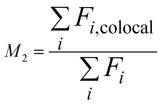 | (3) |
Values for Mander's coefficients range from 0 to 1, where 0 indicates no pixel overlap and 1 indicates full pixel overlap.
The angular acceleration of the rotor was determined using the solid mechanics interface and setting the boundary load condition, S·n, to be:
| S·n = −P·A·n | (4) |
2.3 Silver nanoparticle synthesis
Deionized (DI) water (R = 18 MΩ) was used throughout all nanoparticle syntheses. All inlet solutions were filtered through a 0.22 μm filter to remove any particulates that could interfere with nanoparticle synthesis or characterization. All chemicals used were of analytical grade. AgNP reactions were carried out through the reduction of AgNO3 (Acros) with NaBH4 (Sigma). For all syntheses results presented here, 3 mM NaBH4 was injected into inlet 1, while 0.5 mM of AgNO3 was injected into inlet 2 (Fig. 1). The flow rates into each inlet were equal in all experiments. For instance, a total flow rate of 8 mL min−1 consisted of each reagent flowing at a rate of 4 mL min−1. Reacted samples were capped with 0.6 mM tri-sodium citrate (Sigma) off-chip immediately after collection. Devices were rigorously cleaned between each synthesis run to remove any trapped particles or residual reagents. Trapped material was readily cleared away using the appropriate solvents, including strong oxidizers which do not attack silicon or glass.3 Results and discussion
3.1 Rotational velocity measurements
The experimental measurement of the angular velocity of the microturbine with the inlet flow rate rotational velocity measurement of the rotor provided valuable insights for the control of mixing time. Fig. 5 plots the rotational speed of the rotor versus total inlet flow rate. The results are reproducible at flow rates ranging from 4.5 mL min−1 to 7.5 mL min−1, corresponding to an increase in rotational speed from 20000 rpm to 60000 rpm. The overall reduction in rotational speed obtained experimentally versus that predicted by simulation is attributed to the frictional forces between the rotor and the stator, which were not accounted for in the COMSOL model. Friction is expected to have a more pronounced affect at lower flow rates, as was observed experimentally. When the rotational speed falls below 20000 rpm, the rotor would frequently stall.
 | ||
| Fig. 5 Experimentally and computationally determined (COMSOL Multiphysics) rotational velocities as a function of flow rate. Experimental data is plotted as average velocity of 5 runs: error bars represent range of values. | ||
When the spin speeds exceeds 60000 rpm, the rate of increase in rotational speed with flow rate decreases. This phenomenon has been supported by previous studies,35 which reveal that as the turbine's angular velocity increases, a greater portion of the fluid volume becomes entrained (Fig. 1). This flow mode is less efficient than the crossflow at energy extraction. Both the experimental outcomes and simulation data reveal a consistent trend of reduced momentum transfer efficiency at these elevated flow rates. Moreover, at these heightened flow rates, there is a significant increase in the standard deviation of the measurements. This variability is likely due to cavitation resulting from the pressure inside the microturbine dropping below the vapor pressure of water,39 creating vibrations that affect rotational velocity and reproducibility. This is supported by COMSOL modeling of the pressure inside the microturbine, which drops sufficiently at such high flow rates to allow fluid phase transitions (ESI,† S2).
3.2 Co-localization analysis of mixing
To analyze mixing efficiency, co-localization fluorescence imaging was applied to analyze the spatial distribution of two fluorescent dyes within a defined volume as they exited the rotor. The Pearson correlation coefficient (PCC) was determined within the region of interest (ROI), defined to be within a distance of 0 to 800 μm from the fluid point of exit at the edge of the turbine down the outlet channel (Fig. 6). At the turbine outlet (0 μm), the PCC was 0.78, resulting from the different flow patterns: fluorescein mostly follows a crossflow pattern, while rhodamine is mostly entrained flow, which becomes distributed across the channel as it exits. This is confirmed by the Mander's M2 coefficient at this point, which is 0.55, showing that rhodamine is present in nearly twice the volume of the channel as fluorescein. Mixing improves rapidly as the fluid travels down the outlet channel. PCC increases to 0.90 at a distance of 100–200 μm and reaches 0.93 between 200–300 μm, indicating nearly complete, homogeneous mixing. In comparison, at low flow velocities (stationary rotor) a laminated flow profile is obtained (Fig. 6a) with a PCC of only 0.02 at 800 μm down the outlet channel, as mixing is only by molecular diffusion. With the rotor spinning, a reduced velocity zone forms at 400 μm down the outlet channel, which according to the Mander's coefficient, is predominantly populated by Rhodamine, as shown in Fig. 6c. This is where rhodamine is concentrated before the rotor starts to spin, and becomes entrapped when the rotor is spinning. However, beyond 500 μm, the PCC values stabilize, to values comparable to those at 100 μm from the outlet. These findings are in good agreement with mixing profiles obtained using COMSOL Multiphysics simulations, shown in Fig. 6b and d. In the simulation (Fig. 6d), the low velocity zone has a concentration of 0 mM, since the entire device's initial fluid concentration was set to 0 mM in the model, instead of the laminated concentration profile obtained in experiment.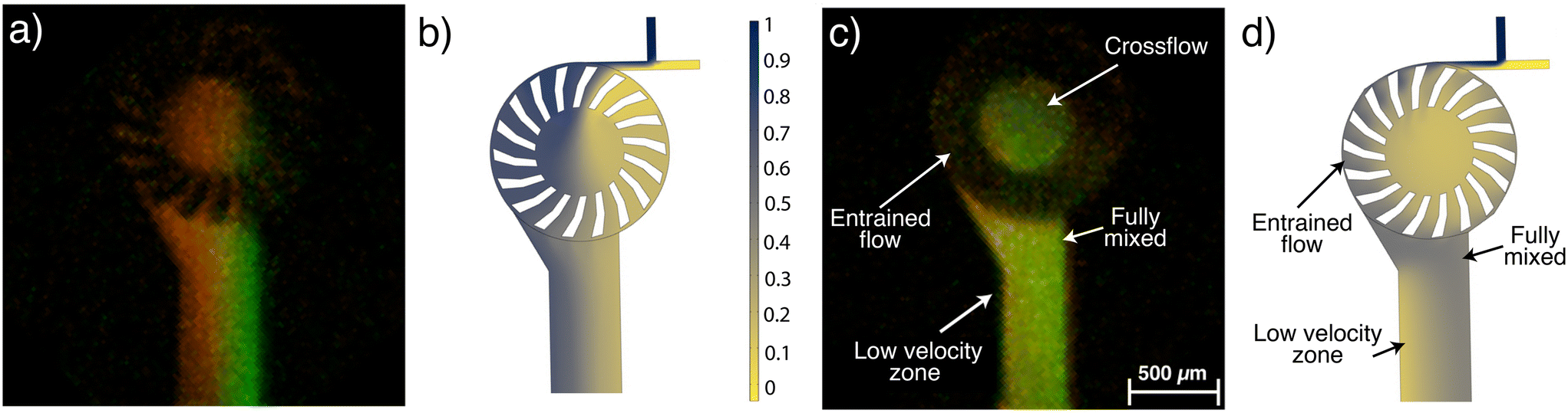 | ||
| Fig. 6 Mixing profiles of (a) experimental and (b) simulated fluids, showing lamination for stationary rotor. (c) Merged channels of steady state flow (7 mL min−1 total, rotor spinning) and (d) simulated. The fluorescence image resolution is approximately 3.6 μm per pixel. | ||
This in-depth understanding of the fluid flow pattern within the microturbine mixer was key to optimizing the experimental protocol for ultra-small silver nanoparticles (AgNPs) synthesis (section 3.4).
3.3 Determination of mixing time
For such a complex mixing profile, some assumptions were made in order to estimate the time required to achieve ≥90% mixing. The mixer was divided into three sections, each of which contributes to mixing. The first section is where the two fluids initially meet within the driving nozzle. The second section is within the turbine, and the final section is the initial 100 μm of outlet channel, where 90% mixing is achieved according to the co-localization analysis (Fig. 7). Residence times in each section were calculated based on flow rate. The nozzle residence time is simply the nozzle fluid volume divided by flow rate. The rotor residence time is determined by the crossflow fluid volume, calculated with COMSOL Multiphysics (ESI,† Fig. S3–S5). Simulation results show that the entrained flow becomes fully mixed before exiting the rotor by means of fluidic vortices generated between the blades. Therefore, the crossflow residence time is deemed to be the limiting factor. The time required to travel 100 μm down the outlet channel is the volume of that outlet channel section divided by flow rate. Fig. 8 plots the mixing times for each region of the mixer as a function of flow rate. For a total inlet flow rate between 4–9 ml min−1, the calculated time to achieve ≥90% mixing is 0.580–0.290 ms, respectively. This is comparable to mixing times reported for some other high-speed microfluidic mixers that also report achieving ≥90% mixing across the full width of the fluidic channel.40–43 A few report mixing times <50 μs, but as a consequence of their requisite small dimensions, they have an order of magnitude lower throughput than the microturbine. Throughput is potentially a significant advantage for the synthesis of products where large quantities are needed. | ||
| Fig. 7 PCC and MCC of fluorescence image of mixing in the microturbine at steady state. ROI down the outlet channel is depicted within the inset where each box represents a 100 μm analysis area. | ||
 | ||
| Fig. 8 Contributions to mixing time from different regions in the microturbine for ≥90% mixing as a function of flow rate. | ||
It should be noted that the methods used to analyze mixing in these other mixers are prone to measurement limitations that will underestimate the actual mixing time. The two most commonly used methods for analyzing mixing efficiency are dilution and fluorescence quenching. The dilution method mixes a liquid containing a dye with a transparent liquid, while the fluorescence quenching method mixes fluorescent molecules with a quencher. With both methods, the mixing process is visualized by imaging optical intensity or color, and mixing is considered complete when the image intensity becomes uniform throughout the channel (i.e., pixel intensities flatline). But, relying solely on stable pixel intensities to indicate complete mixing is subject to many sources of error such as saturation, photobleaching, and detector sensitivity, which can lead to inaccurate assessments of mixing time and efficiency.
In the co-localization method, two fluorescent probes are used to obtain a quantitative assessment of flow profiles and mixing by applying the Pearson's correlation coefficient (PCC) and Mander's correlation coefficient (MCC). The PCC quantitatively measures the linear relationship between the two components in the mixture, providing insight into the overall uniformity of the fluids. Additionally, MCC enables the quantification of spatial overlap between two reagents, allowing the evaluation of homogeneity between the two fluorescent probes within the fluidic channel. For comparison, the dilution method was applied to the microturbine, by measuring the fluorescence intensity of each mixing dye as it exited the rotor. The intensity flattens within 25 μm of the rotor edge, and provides none of the detail obtained by the co-localization method.
3.4 Silver nanoparticle synthesis
To achieve a size-controllable synthesis of ultra-small AgNPs, we considered both chemical and fluidic experimental parameters. The chemical reagents and concentrations specified earlier were chosen based on previous optimization experiments.44 Further optimization of the synthesis protocol involved careful attention to the flow patterns throughout the mixer. As mentioned earlier, a low velocity zone is produced in the outlet channel. The fluid that predominantly resides in that zone is from inlet 1, due to the laminar flow, which precedes the point at which the fluid force on the rotor blades overcomes the frictional force between the rotor and stator and rotation starts (Fig. 1 and 6). Introducing AgNO3 into inlet 1 would result in the presence of unreacted Ag ions in this region, which can diffuse into the mixed volume, resulting in an increase in both size and distribution of AgNPs, as was observed experimentally (ESI,† Fig. S6). By introducing NaBH4 into inlet 1, the fluid in this region will not contribute to the size distribution of the AgNPs, which critically depends on the mixing time and homogeneity. Additionally, since NaBH4 serves the dual purpose of being both a reducing agent and a capping agent, it will enhance the stability of the AgNPs that encounter this fluid interface.Having established the optimal inlet assignment for each reagent, the influence of flow rate on AgNP size and distributions was investigated. As shown in Fig. 9, a low flow rate of 4 mL min−1, where frictional forces between stator and rotor interfere with the optimal rotational mechanics of the turbine, resulted in a higher variability in AgNP sizes, likely due to fluctuations in the rotor's rotational speed between experiments. This affects the mixing time, shown in Fig. 5, the bulk of which is determined by the rotational velocity of the rotor. At flow rates between 5–8 mL min−1, optimal AgNP reproducibility was achieved, reflecting the high degree of reproducibility in rotational velocity in this range, and confirming that the rotational velocity of the rotor plays a significant role in the formation of AgNPs.
 | ||
| Fig. 9 (Top) AgNP volume distributions for particles synthesized within a microturbine. (Bottom) DLS size distributions depicting the influence on particle size and flow rate. | ||
Dynamic light scattering (DLS) measurements confirms that faster mixing times lead to the formation of smaller AgNPs as rapid mixing promotes more efficient nucleation and growth during particle formation. As mixing times decrease, there is less time for individual Ag ions to cluster and form larger aggregates, thus leading to more uniform nucleation and particle growth as shown in Fig. 9, where we observed a decrease in both particle size and polydispersion as flow rate increased. This trend continued up to a flow rate of 8 mL min−1. This is further confirmed through TEM measurements as shown in Fig. 10 where the average particle size was determined to be 4.45 (±0.97) nm at a flow rate of 5 mL min−1 and 1.76 (±0.70) nm at a flow rate of 7 mL min−1. At a flow rate of 9 mL min−1, an increase in AgNPs size and variance was obtained, attributed to fluctuating mixing times resulting from instabilities in rotation velocity (Fig. 5), possibly due to cavitation.
 | ||
| Fig. 10 TEM images of AgNPs synthesized at a total flow rate of (left) 5 mL min−1 and (right) 7 mL min−1. Size distribution histogram for each image are shown in insets. | ||
We were consistently able to perform >50 runs (50 ml) per microfluidic device, for combined characterization testing and syntheses, over a period of 6 months. Device failure always resulted from operator error, e.g. clogging of the rotor due to inadequate solution filtering or overtightening of the interconnection jig, resulting in stress cracking of the bonded glass. Cleaning of the device with strong oxidizers restored clogged device operation, whereas cracking is not repairable. Micro-pitting of the rotor blades was observed after running the mixer at high flow rates (≥7 mL min−1), where cavitation is likely to occur (per COMSOL simulation, ESI†). However, the pitting did not impact the device's mixing performance. More than 20 sequential syntheses were performed on individual devices at the flow rate of 8 ml min−1, producing 50 ml per run (>1 liter total sample volume). Higher sample volumes can be attained by running multiple devices in parallel.
4 Conclusions
In conclusion, a microturbine based, high speed microfluidic mixer was microfabricated in silicon, and its mixing performance analyzed. This design was demonstrated to achieve rotational velocities of 20–60 krpm, which is >10× faster than previously reported fluidically driven microrotors. The mixing speed of two reagents was controlled by varying rotational velocity with flow rate, achieving sub millisecond mixing times at rotor rotational speeds of 20–60 krpm. Co-localization fluorescence image analysis and COMSOL Multiphysics simulations were performed to obtain flow profiles. Simulations very closely matched our experimental results, demonstrating the utility of applying co-localization imaging to the analysis of microfluidic mixing. A low flow velocity zone, which is inherent to turbines operating at high rotational velocity, was identified. Applying characterization results, the synthesis protocol for AgNPs was optimized by assigning the limiting (AgNO3) and excess reactants (NaBH4) to the appropriate fluidic inlets, keeping Ag ions out of the low recirculating zone where they could be a source for aggregation. As evidenced by DLS measurements and TEM imaging, faster mixing times resulted in the synthesis of smaller nanoparticles by promoting more uniform dispersion and reduced agglomeration of precursor materials. Results demonstrate the microturbine mixer to be effective in controlling kinetically-limited systems, such as the synthesis of ultra-small AgNPs, in a highly reproducible fashion.Data availability
Compiled data, in support of the findings of this study, is included within the article and ESI.† Additional information such as raw measurement files and COMSOL simulation parameters may be obtained from the corresponding author upon reasonable request.Author contributions
SDC, RLS and MDM: conceptualization, supervision and resources; SDC and RLS: project administration, funding acquisition and methodology; AEE and CLE: investigation; AEE: formal analysis and visualization; SDC, AEE and CLE: writing – draft; RLS, AEE and MDM: writing, review, and editing.Conflicts of interest
There are no conflicts to declare.Acknowledgements
Research reported in this publication was supported by an Institutional Development Award (IDeA) from the National Institute of General Medical Sciences of the National Institutes of Health under grant number P20GM103423, and by a Major Research Instrumentation Award from the National Science Foundation under grant number 2406727. A. E. E. received stipend support from the University of Maine's Institute of Medicine. The authors thank Pete Finger of the Jackson Laboratory, Bar Harbor, ME, for TEM imaging.References
- J. R. McBride, A. D. Dukes, M. A. Schreuder and S. J. Rosenthal, Chem. Phys. Lett., 2010, 498, 1–9 CrossRef CAS PubMed.
- B. H. Kim, M. J. Hackett, J. Park and T. Hyeon, Chem. Mater., 2014, 26, 59–71 CrossRef CAS.
- C. B. Whitehead, M. A. Watzky and R. G. Finke, J. Phys. Chem. C, 2020, 124, 24543–24554 CrossRef CAS.
- T. Egawa, J. L. Durand, E. Y. Hayden, D. L. Rousseau and S.-R. Yeh, Anal. Chem., 2009, 81, 1622–1627 CrossRef CAS PubMed.
- A. E. Kamholz, B. H. Weigl, B. A. Finlayson and P. Yager, Anal. Chem., 1999, 71, 5340–5347 CrossRef CAS PubMed.
- A. Jahn, W. N. Vreeland, M. Gaitan and L. E. Locascio, J. Am. Chem. Soc., 2004, 126, 2674–2675 CrossRef CAS PubMed.
- N.-T. Nguyen and X. Huang, Lab Chip, 2005, 5, 1320–1326 RSC.
- V. Mengeaud, J. Josserand and H. H. Girault, Anal. Chem., 2002, 74, 4279–4286 CrossRef CAS PubMed.
- A. D. Stroock, S. K. W. Dertinger, A. Ajdari, I. Mezic, H. A. Stone and G. M. Whitesides, Science, 2002, 295, 647–651 CrossRef CAS PubMed.
- T. Scherr, C. Quitadamo, P. Tesvich, D. S.-W. Park, T. Tiersch, D. Hayes, J.-W. Choi, K. Nandakumar and W. T. Monroe, J. Micromech. Microeng., 2012, 22, 055019 CrossRef PubMed.
- J. Yang, L. Qi, Y. Chen and H. Ma, Chin. J. Chem., 2013, 31, 209–214 CrossRef CAS.
- Q. Zeng, F. Guo, L. Yao, H. Zhu, L. Zheng, Z. Guo, W. Liu, Y. Chen, S. Guo and X. Zhao, Sens. Actuators, B, 2011, 160, 1552–1556 CrossRef CAS.
- H. V. Phan, M. B. Coşkun, M. Şeşen, G. Pandraud, A. Neild and T. Alan, Lab Chip, 2015, 15, 4206–4216 RSC.
- C. Wang, B. Rallabandi and S. Hilgenfeldt, Phys. Fluids, 2013, 25, 022002 CrossRef.
- C.-C. Chang and R.-J. Yang, Microfluid. Nanofluid., 2007, 3, 501–525 CrossRef CAS.
- J. C. Baygents and F. Baldessari, Phys. Fluids, 1998, 10, 301–311 CrossRef CAS.
- C.-H. Chen, H. Lin, S. K. Lele and J. G. Santiago, J. Fluid Mech., 2005, 524, 263–303 CrossRef.
- H. H. Bau, J. Zhong and M. Yi, Sens. Actuators, B, 2001, 79, 207–215 CrossRef CAS.
- Y. Kim, J. Lee and S. Kwon, J. Micromech. Microeng., 2009, 19, 105028 CrossRef.
- S. Kim, J. Kim, Y.-H. Joung, S. Ahn, C. Park, J. Choi and C. Koo, Lab Chip, 2020, 20, 4474–4485 RSC.
- C. A. Mockmore and F. Merryfield, The Banki Water Turbine, 1949 Search PubMed.
- D. M. Eby, H. R. Luckarift and G. R. Johnson, ACS Appl. Mater. Interfaces, 2009, 1, 1553–1560 CrossRef CAS PubMed.
- M. Rai, A. Yadav and A. Gade, Biotechnol. Adv., 2009, 27, 76–83 CrossRef CAS PubMed.
- Z. Jiang, W. Yuan and H. Pan, Spectrochim. Acta, Part A, 2005, 61, 2488–2494 CrossRef PubMed.
- J. M. J. Santillán, D. M. Arboleda, D. Muraca, D. C. Schinca and L. B. Scaffardi, Sci. Rep., 2020, 10, 8217 CrossRef PubMed.
- A. Campos, N. Troc, E. Cottancin, M. Pellarin, H.-C. Weissker, J. Lermé, M. Kociak and M. Hillenkamp, Nat. Phys., 2019, 15, 275–280 Search PubMed.
- M. Smithard, Solid State Commun., 1973, 13, 153–156 CrossRef CAS.
- U. Kreibig, J. Phys. C:Solid State Phys., 1974, 4, 999 CrossRef CAS.
- V. Vidhu and D. Philip, Micron, 2014, 56, 54–62 CrossRef CAS PubMed.
- G. Liao, J. Fang, Q. Li, S. Li, Z. Xu and B. Fang, Nanoscale, 2019, 11, 7062–7096 RSC.
- M. Takesue, T. Tomura, M. Yamada, K. Hata, S. Kuwamoto and T. Yonezawa, J. Am. Chem. Soc., 2011, 133, 14164–14167 CrossRef CAS PubMed.
- L. Xu, J. Peng, M. Yan, D. Zhang and A. Q. Shen, Chem. Eng. Process.: Process Intesif., 2016, 102, 186–193 CrossRef CAS.
- T. Maki, S. Takeda, Y. Muranaka and K. Mae, Front. Chem. Eng., 2021, 3, 742322 CrossRef.
- R. Baber, L. Mazzei, N. T. K. Thanh and A. Gavriilidis, RSC Adv., 2015, 5, 95585–95591 RSC.
- J. D. Andrade, C. Curiel, F. Kenyery, O. Aguillón, A. Vásquez and M. Asuaje, Int. J. Rotat. Mach., 2011, 2011, 1–12 CrossRef.
- S. Bolte and F. P. Cordeliéres, J. Microsc., 2006, 224, 213–232 CrossRef CAS PubMed.
- F. R. Menter, AIAA J., 1994, 32, 1598–1605 CrossRef.
- D. C. Wilcox, AIAA J., 2012, 46, 2823–2838 CrossRef.
- R. C. Adhikari, J. Vaz and D. Wood, Energies, 2016, 9, 237 CrossRef.
- R. K. Ramamoorthy, E. Yildirim, I. Rodriguez-Ruiz, P. Roblin, L.-M. Lacroix, A. Diaz, R. Parmar, S. Teychené and G. Viau, Lab Chip, 2023, 24, 327–338 RSC.
- Z. Lu, J. McMahon, H. Mohamed, D. Barnard, T. R. Shaikh, C. A. Mannella, T. Wagenknecht and T.-M. Lu, Sens. Actuators, B, 2010, 144, 301–309 CrossRef CAS PubMed.
- Y. Li, D. Zhang, X. Feng, Y. Xu and B.-F. Liu, Talanta, 2012, 88, 175–180 CrossRef CAS PubMed.
- R. C. Itani, M. M. Cohen and A. Tokmakoff, Rev. Sci. Instrum., 2023, 94, 034102 CrossRef CAS PubMed.
- M. A. Moyet, M. R. Hossen, A. Ward, O. Adams, M. D. Mason, S. D. Collins and R. L. Smith, 2020 IEEE 33rd International Conference on Micro Electro Mechanical Systems (MEMS), 2020, pp. 1137–1140 Search PubMed.
Footnotes |
| † Electronic supplementary information (ESI) available. See DOI: https://doi.org/10.1039/d5lc00488h |
| ‡ Deceased. Date of death: [May 31, 2024]. |
| This journal is © The Royal Society of Chemistry 2025 |