
 Open Access Article
 This Open Access Article is licensed under a Creative Commons Attribution-Non Commercial 3.0 Unported Licence
Rapid wet-chemical oxidative activation of graphite felt electrodes for vanadium redox flow batteries†
Brian Shanahan‡
 a,
Khaled Seteiz‡a,
Philipp A. Heizmannab,
Susanne Kochac,
Jan Büttnerbde,
Siham Ouardif,
Severin Vierrathabc,
Anna Fischer*bdeg and
Matthias Breitwieser*ac
a,
Khaled Seteiz‡a,
Philipp A. Heizmannab,
Susanne Kochac,
Jan Büttnerbde,
Siham Ouardif,
Severin Vierrathabc,
Anna Fischer*bdeg and
Matthias Breitwieser*ac
aElectrochemical Energy Systems, Laboratory for MEMS applications, IMTEK – Department of Microsystems Engineering, University of Freiburg, Georges-Koehler-Allee 103, 79110 Freiburg, Germany. E-mail: matthias.breitwieser@imtek.de
bFIT, University of Freiburg, Georges-Koehler-Allee 105, 79110 Freiburg, Germany. E-mail: anna.fischer@ac.uni-freiburg.de
cHahn-Schickard, Georges-Koehler-Allee 103, 79110 Freiburg, Germany
dInstitute for Inorganic and Analytical Chemistry, University of Freiburg, Alberstr. 21, 79104 Freiburg, Germany
eCluster of Excellence livMatS, University of Freiburg, 79104 Freiburg, Germany
fFraunhofer Institute for Solar Energy Systems ISE, Heidenhofstr. 2, 79110 Freiburg, Germany
gFMF—Freiburg Materials Research Center, University of Freiburg, Stefan-Meier Str. 21, 79104 Freiburg, Germany
First published on 29th September 2021
Abstract
To boost the performance of vanadium redox flow batteries, modification of the classically used felt electrodes is required to enable higher cycling performance and longer life cycles. Alternative approaches to the standard thermal oxidation procedure such as wet chemical oxidation are promising to reduce the thermal budget and thus the cost of the activation procedure. In this work we report a rapid 1 hour activation procedure in an acidified KMnO4 solution. We show that the reported modification process of the felt electrodes results in an increase in surface area, density of oxygenated surface functionalities as well as electrolyte wettability, as demonstrated by N2-physisorption, XPS, Raman spectroscopy as well as contact angle measurements. The activation process enables battery cycling at remarkably high current densities up to 400 mA cm−2. Stable cycling at 400 mA cm−2 over 30 cycles confirms promising stability of the reported activation procedure.
Introduction
Clean energy generation requires development of clean energy storage such as hydrogen for mobility and batteries for stationary storage. Future smart grid infrastructure will require more integrated stationary energy storage solutions. Redox flow batteries (RFB) are considered an important energy storage system with the vanadium redox flow battery (VRFB) getting most attention due to its simple design, minimal upkeep costs and long operational life.1–5 One of the most important components in a VRFB is the electrodes. The role of the electrodes is to ensure efficient electron charge transfer and to facilitate the vanadium redox reactions on their surface.6 The most common electrode type used in VRFBs is a soft graphite felt produced from polyacrylonitrile (PAN). Graphite felts are cheap to produce, chemically stable, have low electrical resistance and once activated, assume the role of catalyst reaction site for the vanadium redox reactions due to the incorporation of surface-based oxygen functional groups and defect sites.7–10 Rayon, which is based on a cellulose precursor, is another material commonly used to produce graphite felts which has different physical and chemical characteristics than PAN based felts such as lower electrical conductivity, bundle fibre morphology resulting in increased surface roughness and increased tendency for formation of surface oxygen functionality during activation.11–14 The use of strong oxidizing compounds has been shown to be a very promising activation method of Rayon based electrodes leading to both significant oxygen-based surface functionality15,16 and increased surface area through thermochemical decomposition.17–19 Deng et al. demonstrated a reduced graphene oxide graphite felt (rGO-GF) with high electrocatalytic redox reversibility towards V2+/V3+ and VO2+/VO2+ redox couples.20 The rGO-GF composite electrode contained abundant oxygen functional groups resulting in high electron conductivity and outstanding stability compared to the pristine graphite felt electrode. At current densities of 300 mA cm−2 they obtained an energy efficiency (EE) of 60%. Furthermore, Chen et al., prepared a surface-wrinkle-modified GF with high oxygen and nitrogen functionalities prepared by a hydrothermal method followed by calcination resulting in stable average EE of 78% at 150 mA cm−2 (ref. 21) It should be noted that at a high current density of 300 mA cm−2 the EE was also 60%. Wang et al. reported a three-dimensional network in the GF electrode.22 This network with abundant oxygen functional groups exhibited improved performance compared to the untreated GF. Jiang et al. recently reported a room temperature procedure to activate rayon-based graphite felt electrodes for VRFB applications via treatment in an aqueous potassium permanganate (KMnO4) solution.23 The authors demonstrated that immersing electrodes for up to five days in aqueous potassium permanganate solutions with concentrations between 0.1–0.3 M was sufficient to generate a porous and catalytically active electrode surface that was capable of facilitating both the positive and negative vanadium redox couples. In this work, we utilize an acidified KMnO4 solution that results in a significantly faster activation process (1 hour vs. 5 days for the work of Jiang et al.) and results in an electrode with improved hydrophilic properties, higher active surface areas, no residual Mn based deposits and improved kinetics for the four vanadium redox reactions. Due to these improvements, stable single cell battery cycling up to 400 mA cm−2 could be demonstrated.Methods
Materials used
The electrolyte, activation and neutralization solutions were prepared using the following reagents: VOSO4 (99.9% abcr GmbH), KMnO4 (99% Grüssing GmbH), H2SO4 (96% Sigma Aldrich), H2O2 (30% Carl Roth), HNO3 (65% Sigma Aldrich) and H3PO4 (85% Sigma Aldrich). Electrodes used for this study are SGL Sigracell GFA6-EA Rayon-based graphite felt electrodes. The electrodes were received from SGL carbon without any additional pre-activation and/or purification steps. For all single cell electrochemical testing, a Nafion® 212 membrane (Ion Power GmbH) was used.Electrode preparation
Electrodes were cut from a pristine Sigracell GFA6-EA electrode sheet using a hole punch. Subsequently, these pristine electrode samples were cut into two equal pieces along their cross section to yield two 3 mm thick electrodes denoted as P-GF electrodes. Thermally activated graphite felt electrodes (T-GF) were prepared by treating P-GF electrodes in a tube furnace (0TF-1200X-S, MTI Corporation, USA) at 400 °C under an air atmosphere with a heating rate of 5 °C min−1 and a holding time of 6 h. KMnO4 activated graphite felts (K-GF) are fabricated in a two-step process. The first step involves reacting the pristine graphite electrode (P-GF) surface with acidified potassium permanganate (KMnO4) activation solution which results in the electrode surface becoming decorated with MnOx layers. The KMnO4 stock solutions were prepared by dissolving KMnO4 in deionized water (DI water). The activation solutions were prepared by mixing 19 mL of the appropriate KMnO4 stock solution with 1 mL acid (for concentrations of KMnO4 solutions and the type of acid used, see Table 1). The second step is removal of the MnOx layers by immersion of the electrodes in 30 mL of neutralization solution at room temperature (1![[thin space (1/6-em)]](https://www.rsc.org/images/entities/char_2009.gif) :1 ratio 2 M H2SO4 with 100 mM H3PO4:3% H2O2 solution) followed by washing in DI water for 1 minute with stirring. The neutralization solution and DI water washing steps were repeated three times to ensure completed removal of all MnOx layers on the electrodes surface. The resulting K-GF electrode was then dried overnight in an oven at 80 °C. To optimize the fabrication process of K-GF electrodes, essential parameters such as KMnO4 concentration, solution temperature, immersion time and acid type on the performance of the modified felt electrodes were assessed by cyclic voltammetry (CV) in 80 mL of 1:1 ratio 0.1 M VO2+:VO2+ in 2 M H2SO4 with 100 mM H3PO4 solution. All half-cell electrochemical measurements were performed three times to ensure reproducibility across all samples. Testing variations are listed in Table 1.
:1 ratio 2 M H2SO4 with 100 mM H3PO4:3% H2O2 solution) followed by washing in DI water for 1 minute with stirring. The neutralization solution and DI water washing steps were repeated three times to ensure completed removal of all MnOx layers on the electrodes surface. The resulting K-GF electrode was then dried overnight in an oven at 80 °C. To optimize the fabrication process of K-GF electrodes, essential parameters such as KMnO4 concentration, solution temperature, immersion time and acid type on the performance of the modified felt electrodes were assessed by cyclic voltammetry (CV) in 80 mL of 1:1 ratio 0.1 M VO2+:VO2+ in 2 M H2SO4 with 100 mM H3PO4 solution. All half-cell electrochemical measurements were performed three times to ensure reproducibility across all samples. Testing variations are listed in Table 1.
| Test number | KMnO4 conc. (M) | Temperature (°C) | Time (h) | Acid |
|---|---|---|---|---|
| 1 | 0.1* | 70 | 1 | H2SO4 |
| 2 | 0.2* | 70 | 1 | H2SO4 |
| 3 | 0.3* | 70 | 1 | H2SO4 |
| 4 | 0.1 | 70 | 0.5* | H2SO4 |
| 5 | 0.1 | 70 | 1* | H2SO4 |
| 6 | 0.1 | 70 | 2* | H2SO4 |
| 7 | 0.1 | 70 | 3* | H2SO4 |
| 8 | 0.1 | 70 | 4* | H2SO4 |
| 9 | 0.1 | 50* | 1 | H2SO4 |
| 10 | 0.1 | 60* | 1 | H2SO4 |
| 11 | 0.1 | 70* | 1 | H2SO4 |
| 12 | 0.1 | 80* | 1 | H2SO4 |
| 13 | 0.1 | 70 | 1 | H2SO4* |
| 14 | 0.1 | 70 | 1 | H3PO4* |
| 15 | 0.1 | 70 | 1 | HNO3* |
Material characterization
Scanning electron microscopy (SEM) images were acquired using a FEG-SEM Amber X (Tescan) equipped with a secondary electron in-lens detector and an Everhart–Thornley detector. All images were acquired with a working distance of 3 mm applying an acceleration voltage of 2 kV and a beam current of 100 pA. The pore size distribution (PSD) and specific surface area were determined by isothermal nitrogen physisorption with an Autosorb-1 (Quantachrome), by applying a quenched solid density functional theory (QSDFT) model and the Brunauer–Emmett–Teller (BET)-model, respectively, to the adsorption desorption isotherms. For the PSD both adsorption and desorption branches were evaluated, whereas the appropriate range for the BET-analysis was chosen by 2 criteria: first a positive C constant (y-intercept of the BET-plot) and second an evaluation of the adsorption branch according to the criteria proposed by Rouquerol et al.24 The composition and the chemical state of the surface was analysed by means of X-ray photoelectron spectroscopy (XPS) measurements using an EnviroESCA laboratory system (SPECS Surface Nano Analysis, GmbH, Germany). A monochromatized Al Kα X-ray source with an excitation energy of 1486.6 eV and a spot size of 300 μm diameter was used. All samples were measured at room temperature under a pressure of ca. 10−7 mbar. Micro X-ray fluorescence (μXRF) was conducted using a Bruker M4 TORNADO. An element mapping was acquired under vacuum conditions using a spot size (SS) of 20 μm with a spot separation of 80 μm. A scan rate of 15 ms per point was used with a source current of 600 μA with a beam incidence angle of 50°. The detector energy resolution was set to 40 eV and an input count rate of 130 kcps. Raman spectra of the D and G bands, associated with sp2 and sp3 hybridized carbons,8 were obtained using a WITec alpha 300 confocal Raman microscope with a 532 nm laser operated at 10 ± 1 mW as the excitation source. Average spectra for the P-GF, T-GF and K-GF electrodes were produced by averaging five single spectra from each respective electrode. All single spectra were integrated for 0.5 s and accumulated ten times. The ratio of the D band and G band intensities (ID/IG) were obtained by dividing the amplitude of the D-band by the amplitude of G-band after applying a Lorentz fit. The respective error of ID/IG of was calculated by error propagation with the obtained values from the Lorentz fit. Background subtraction and fitting was done using WITec project. Contact angle measurements of electrodes were obtained using a Dataphysics OCA 15 plus. Samples used were 1 cm2 in size and the volume of each water droplet applied to the surface was 5 μL.Electrochemical measurements
Half-cell cyclic voltammetry (CV) was performed using a three-electrode setup consisting of a Pt mesh counter electrode, a saturated calomel reference electrode (SCE) and a glassy carbon rod working electrode which was inserted inside the GF electrodes to make electrical contact and keep the sample stable for the test duration. All positive electrode samples were tested in a positive electrolyte solution with the composition of 1:1 ratio of 0.1 M VO2+:VO2+ in 2 M H2SO4 with 100 mM H3PO4 solution in a voltage window of 0.5 V to 1.2 V vs. SCE. Negative electrode samples are tested in a 1:1 ratio 0.1 M V2+:V3+ in 2 M H2SO4 with 100 mM H3PO4 solution with a voltage window of 0 V to −0.9 V vs. SCE. All testing solutions were purged of dissolved/environmental O2 with N2 bubbling for 5 minutes prior and in between testing. All tests were conducted at room temperature (RT) using a CH Instruments 660 E workstation. Electrochemical double-layer capacitance (EDLC) measurements of the GF electrodes were performed in 2 M H2SO4. The potential window of 0.4–0.9 V vs. SCE was used at different scan rates (200, 150, 100, 50, 20, 10, 5 mV s−1). Single cell electrochemical testing was conducted using a Scribner 857 Redox Flow Cell Test System (Scribner Associates Inc, USA). P-GF, K-GF and T-GF electrodes of 3 mm thickness (uncompressed) with geometric area of 4 cm2 were used for both the positive and negative electrodes. A Nafion 212 membrane was immersed in a 2 M H2SO4 solution for 24 hours prior to cell testing. PTFE hard stop gaskets were used to adjust the electrode compression to 60%. All tests were performed at 25 °C ± 1 °C with a flow rate of 40 mL min−1. An electrolyte precursor solution of 1.6 M VO2+ in 2 M H2SO4 with 100 mM H3PO4 was prepared. The inclusion of small quantities of H3PO4 to the electrolyte, has been reported to provide improved thermal stabilization of the vanadium electrolyte25,26 and reduced polarization resistance of the negative electrode.27 To generate the appropriate vanadium oxidation states on each side of the cell, 60 mL of precursor solution was added to the positive tank and 30 mL to the negative tank. A constant voltage of 1.65 V was applied which converts the precursor in the positive tank from VO2+ to VO2+ and the precursor in the negative tank from VO2+ to V3+ and finally to V2+. Once the current dropped below 4 mA cm−2, the charging step was considered complete and 30 mL of VO2+ was removed from the positive tank to ensure equal volumes of electrolyte on both sides of the cell. Electrochemical impedance spectroscopy (EIS) was performed potentiostatically in the frequency range of 10−1 to 104 Hz with an amplitude of ±10 mV at open circuit voltage (OCV). OCV was obtained by charging the electrolyte to 100% state of charge (SOC) and applying zero current for five minutes. Cycling experiments were conducted at multiple current densities with five cycles at each current density. Upper and lower cell voltage limits of 1.6 V and 0.8 V were used for all cycling experiments. In situ HFR measurements are obtained from the Scribner 857's built in impedance analyser at a frequency of 10 kHz. RCT values of T-GF and K-GF were extracted from the EIS data by the use on an equivalent circuit (Fig. S9†), which was adopted from literature.28
Results & discussion
Preparation of KMnO4 activated graphite felts (K-GF) was conducted in a two-step process as illustrated in Fig. 1. The first step involves reacting P-GF electrodes with acidified KMnO4 solutions, of varying concentrations in order to create abundant surface oxygen functional groups (–COOH, –C![[double bond, length as m-dash]](https://www.rsc.org/images/entities/char_e001.gif) O, –COH) via chemical oxidation of the graphite surface. The addition of an acid to the KMnO4 solution increases the aggressiveness of the reaction on the surface of the P-GF electrode and the reaction takes place as described in eqn (1).23
O, –COH) via chemical oxidation of the graphite surface. The addition of an acid to the KMnO4 solution increases the aggressiveness of the reaction on the surface of the P-GF electrode and the reaction takes place as described in eqn (1).23| 4MnO4− + 3CP-GF + 4H+ → 4“MnO2” + 2H2O + 3CO2 | (1) |
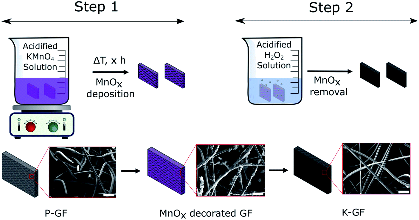 | ||
| Fig. 1 Schematic diagram of the K-GF fabrication process. Step 1 involves the deposition of MnOx layers onto the P-GF electrode surface using acidified KMnO4 solutions. Step 2 involves the removal of MnOx layers using an acidified H2O2 solution to produce the K-GF electrode. SEM images depict the fibre morphology during each stage of the fabrication process. The scale bars in each SEM image represent 50 μm. | ||
After step 1, the electrode surface is decorated with various MnOx layers as evidenced by SEM-EDX (Fig. S1†) and XRF (Fig. S2†). In contrast to the depicted simplified reaction scheme of eqn (1), the overall reaction is much more complicated. The reaction reportedly forms birnessite structures as opposed to just MnO2 (ref. 29) and the liberation of CO2 gas is occasionally not observable on graphite felt electrodes. Instead, the formation of surface based oxygen functional groups (C–OH, CO and COOH) are more common.30–32 The MnO4− anion oxidizes CC bonds throughout the graphite structure, yielding oxygen functional groups. The type of oxygen group yielded depends on the specific location of the CC bond. For example, double bonds located withing the graphite structure tend to form carbonyl (CO) functional groups while those located close to the edge tend to form carboxylic acids (COOH).32 While MnOx coated electrodes are interesting electrodes which have been studied recently,31,33–35 all MnOx deposits in this study were removed prior to electrochemical testing. Therefore, no analysis on the exact oxidation number of Mn in the MnOx deposits was performed. The second step is a cleaning process where the MnOx layers, on the electrode surface, are removed with a neutralization solution and washed with DI water. The final result is an electrode that has no detectable Mn based deposits on its surface (Fig. S2†).
As shown in Fig. 2a, increasing the concentration of KMnO4 from 0.1 M to 0.3 M results in increased peak separations and decreased peak currents. Based upon a previous publication by Jiang et al., in an aqueous KMnO4 solution, a concentration of 0.1 M KMnO4 was found to be optimal as higher concentrations of KMnO4 increase the rate of MnOx deposit formation. As these MnOx deposits grow in size and number, they inhibit further reactions on the electrode surface.23 Consequently, 0.1 M KMnO4 was chosen as the standard concentration for all activation procedures in this work. Immersion time and solution temperature were also assessed in Fig. 2b and c. We found that 1 hour was the optimal time for electrode activation as both longer and short time frames resulted in increased peak separation in the order of 1 hour < 30 minutes < 2 hours < 3 hours < 4 hours. Increasing solution temperature from 50 °C to 80 °C also influences the peak separation in the order 70 °C < 60 °C < 80 °C < 50 °C. As seen in Fig. 2d, the type of acid used, also impacts the peak separation of the redox reactions, more so the VO2+ oxidation peak than the VO2+ reduction peak. Consequently, from the data in Fig. 2 and Table S1,† the optimized parameters for the activation of GFs in this work is immersion for 1 hour at 70 °C in a 0.1 M KMnO4 solution with H2SO4 supporting acid.
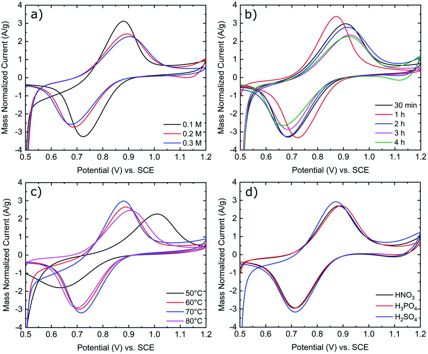 | ||
| Fig. 2 Mass normalized cyclic voltammograms of K-GF electrodes in 1:1 ratio 0.1 M VO2+:VO2+ in 2 M H2SO4 with 100 mM H3PO4 solution. CV was conducted at 5 mV s−1 scan rate at room temperature. (a) Variation of KMnO4 concentration. (b) Variation of immersion time. (c) Variation of solution temperature. (d) Variation of supporting acid. Exact testing conditions of all electrode samples are stated in Table 1. | ||
To verify if the MnOx deposition process and subsequent cleaning steps occurred as expected, SEM-EDX and XRF analysis were conducted after each step. Results are depicted in the ESI (Fig. S1 and S2†). SEM images of the P-GF, T-GF and K-GF electrodes are shown in Fig. 3. The P-GF image shows a very smooth surface with very few open pores. After thermal activation, the T-GF electrodes surface is free from debris but does not appear to have undergone obvious surface structural changes, at least at the examined length scale. The K-GF electrode undergoes a strong structural change compared to the other felts. It features numerous pores and defects on the surface, which are expected to be beneficial for the catalytic activity towards the vanadium redox couples.7,8 The mass of the K-GF electrode decreased by 5.65% (decay from 99.1 mg to 93.5 mg) after treatment while the mass of the T-GF decreased by 3.23% (decay from 99 mg to 95.8 mg). It should be noted that both the T-GF and K-GF electrodes feature similar flexibility as the P-GF electrode, confirming mechanical integrity after treatment (Fig. S3†). The P-GF electrodes specific surface area is 0.74 m2 g−1 which is comparable to the manufacturers reported BET value of 0.8 m2 g−1.36 The BET measurements of the K-GF electrode indicate a specific surface area of 9.93 m2 g−1, which is an increase of over 13 times compared to the P-GF electrode. The T-GF electrode has a specific surface area of 1.11 m2 g−1. For comparison, the aqueous KMnO4 solution reported by Jiang et al., increased the specific surface area of the pristine sample from 2.5 m2 g−1 to 5.5 m2 g−1.23 The average pore radius for the P-GF, T-GF and K-GF electrodes were measured as 52 nm, 37 nm and 2 nm, respectively.
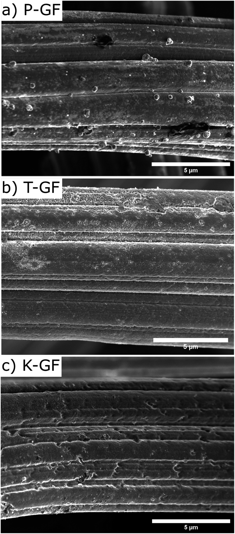 | ||
| Fig. 3 SEM images displaying the surface morphology of (a) P-GF electrode, (b) T-GF electrode and (c) K-GF electrode. | ||
To understand the hydrophobic/hydrophilic nature of the various electrodes, water contact angles were measured for the P-GF, T-GF and K-GF electrodes. The hydrophobicity of the untreated P-GF is clearly evidenced with the high-water contact angle of 157° (Fig. S4†). Both the T-GF and K-GF exhibit significantly improved wettability after treatment, as the contact angle was not measurable due to the immediate absorbance of the liquid into the GF structures. Raman spectroscopy was conducted to identify potential changes in graphitic structure of the various GFs after treatment. Raman analysis of carbonaceous materials is a complex field as depending on the form of carbon material under investigation, a wide range of peaks from 1000 cm−1 to 3000 cm−1 are identifiable.37,38 Typically for VRFB electrode analysis, most focus is given to the two peaks located between 1200–1600 cm−1 which correspond to the G-band (1580 cm−1) and D-band (1350 cm−1).14,39–41 The D-band originates in breathing modes of sp2-atoms in rings and its occurrence signals imperfect graphitic order. The G-band reflects bond stretching or pairs of sp2 hybridized atoms in rings and chains and therefore indicates conjugated sp2 hybridized systems, including graphitic domains.8,42 The ID/IG ratio is used as an indicator for graphitic disorder. The Raman spectra shows that the activated electrodes possess a ratio of 1.24 ± 0.07 and 1.20 ± 0.12 for the K-GF and T-GF respectively, whereas the ratio for the P-GF is 0.92 ± 0.13 (Fig. 4). This indicates that the treated electrodes contain more structural disorder and defects due to the activation process. The increased intensity of the D band with respect to the G-band plus the broadening of both bands in the T-GF and K-GF electrodes correlates to increased structural defects.43
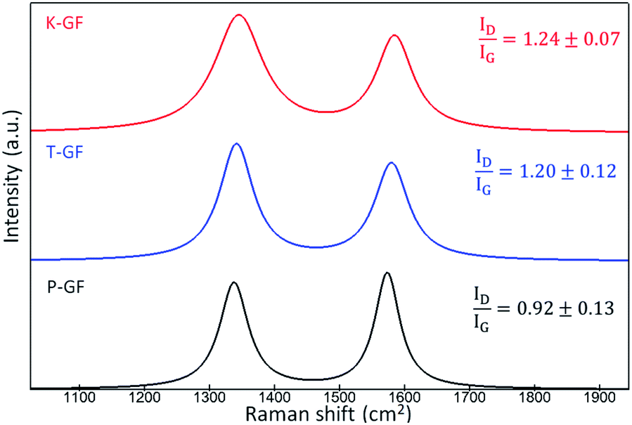 | ||
| Fig. 4 Average Raman spectra indicating the D-band and G-band of P-GF, T-GF and K-GF electrodes. The average spectra are composed of five individual spectra which were fitted and smoothed using WITec Project. | ||
X-Ray photoelectron spectroscopy (XPS) analysis was used to investigate the composition of the surface as well as the chemical states of the elements on the surface. To ensure the homogeneity of the samples, survey spectra are measured at two different positions with a distance of a few mm. Fig. S5a and c,† show the survey spectra of the P-GF and K-GF electrodes, respectively, and each sample is measured at two different positions. The spectra in both positions are identical. Fig. S5b and d,† show semicore states up to 350 eV. Besides the elements C, O, and N, small fractions of the elements S and Si are also present on the surface of both samples. For the P-GF electrode this can be attributed to contamination from the manufacturing process as no additional processing was performed on this sample before conducting XPS analysis.
Important is, that after the activation, no trace of Mn or K is observed on the surface of the K-GF electrode. However, the amounts of both elements S and Si increase after the oxidative activation with KMnO4 solution. The increase in S content can be attributed to adsorbed H2SO4 on the fibre surface as a result of the cleaning step to remove the MnOx deposits. The presence of Si must be linked to the felts manufacturing process as P-GF samples were not exposed to any chemical environment prior to XPS analysis. A possible reason for the increase in Si content is that more Si is exposed in the surface-sensitive XPS measurement in the significantly rougher fibre morphology of the K-GF sample. Table 2 summarized the elemental composition on the surface of P-GF and K-GF as determined from XPS survey spectra.
| Element | C [%] | N [%] | O [%] | S [%] | Si [%] |
|---|---|---|---|---|---|
| P-GF | 91.9 | 1.4 | 5.6 | 0.6 | 0.5 |
| K-GF | 68.3 | 1.8 | 25.0 | 3.0 | 1.9 |
The K-GF sample exhibits the highest amount of O on the surface with 25% compared to the P-GF sample with 5.6%. This result improves the hydrophilic behaviour of the K-GF electrode, as seen in water contact angle measurements. The deconvolution of C 1s core states (Fig. S6a, b† and Table 3) show a decrease in graphitic carbon from 48.2% for P-GF to 31.4% for K-GF electrode and marginal increases in all other non-graphitic carbon peaks, indicating the formation of defects in the graphitic structure which is consistent with our observations from Raman spectroscopy. To determine the chemical states of O on the surface, a peak fitting of the high resolution O 1s core state was carried out and shown in Fig S6c, d,† and the results are summarized in Table 3. The amount of oxygen in different chemical states on the K-GF electrode is changing compared to the P-GF electrode. A relative increase in carbonyl groups (R–CO–R) from 13.7% to 14.9% and carboxyl groups (COOH) from 23.7% to 44.7% and a large relative decrease in hydroxyl (C–OH) groups from 62.6% to 40.4% are observed. EDLC measurements are a useful method to assess the electrode–electrolyte interface as changes to both the wettability and porosity of the electrodes will have an influence on electrode performance and are shown in Fig. S7.† EDLC values were measured as 36 mF g−1 for the P-GF, 234 mF g−1 for the T-GF and 1006 mF g−1 for the K-GF. Reported EDLC values for pristine graphite felt electrode are in the similar range.44 The low EDLC value for the P-GF electrodes are attributed to its hydrophobicity. Since the aqueous electrolyte (2 M H2SO4) has difficulties accessing the entire electrode structure, only a small percentage of the electrode is wetted by the electrolyte and therefore contributes less to the EDLC measurement. The substantial rise in EDLC observed in the K-GF electrodes is the result of the increased electrode wettability and porosity leading to a substantial increase in electrode–electrolyte interactions.
| Peak | Graphite C1 | –C*H2–C2 | C*–COO–C3 | –C*–OH C4 | R–C*O–R C5 | C*OOH C6 | R–CO*–R O1 | C–O*H O2 | CO*OH O3 |
|---|---|---|---|---|---|---|---|---|---|
| Ebin [eV] | 285.4 | 284.8 | 285.6 | 286.5 | 288.7 | 289.5 | 531.46 | 532.2 | 533.6 |
| P-GF (at%) | 48.2 | 21.1 | 12.3 | 10.8 | 0.9 | 6.7 | 13.7 | 62.6 | 23.7 |
| K-GF (at%) | 31.4 | 28.0 | 15.9 | 12.8 | 4.6 | 7.3 | 14.9 | 40.4 | 44.7 |
CV was conducted in the positive and negative electrolytes to evaluate the electrochemical activity of all GF electrodes for the VO2+/VO2+ and V2+/V3+ redox couples. As shown in Fig. 5a, the P-GF electrode shows a VO2+ oxidation peak at about 1.1 V but almost no VO2+ reduction peak in the positive electrolyte. This means, the felt does not efficiently facilitate the conversion of VO2+ to VO2+ and has therefore poor electrochemical reversibility. The normalized peak currents for the oxidation and reduction peaks of the K-GF electrode are significantly higher than the T-GF electrode due to the higher active surface area as measured with BET and EDLC measurements. CV measurements in the negative electrolyte (Fig. 5b) show the same trend with smaller peak to peak separation in the order P-GF > T-GF > K-GF. The P-GF electrode is inactive in the negative electrolyte with no oxidation and reduction peaks. The hydrogen evolution reaction (HER) dominates the reduction reaction of the T-GF electrode in the negative side. However, the K-GF electrode shows a separate reduction peak at −0.7 V before the HER dominates at −0.8 V. Normalized peak currents are higher for the K-GF electrode than the T-GF electrode.
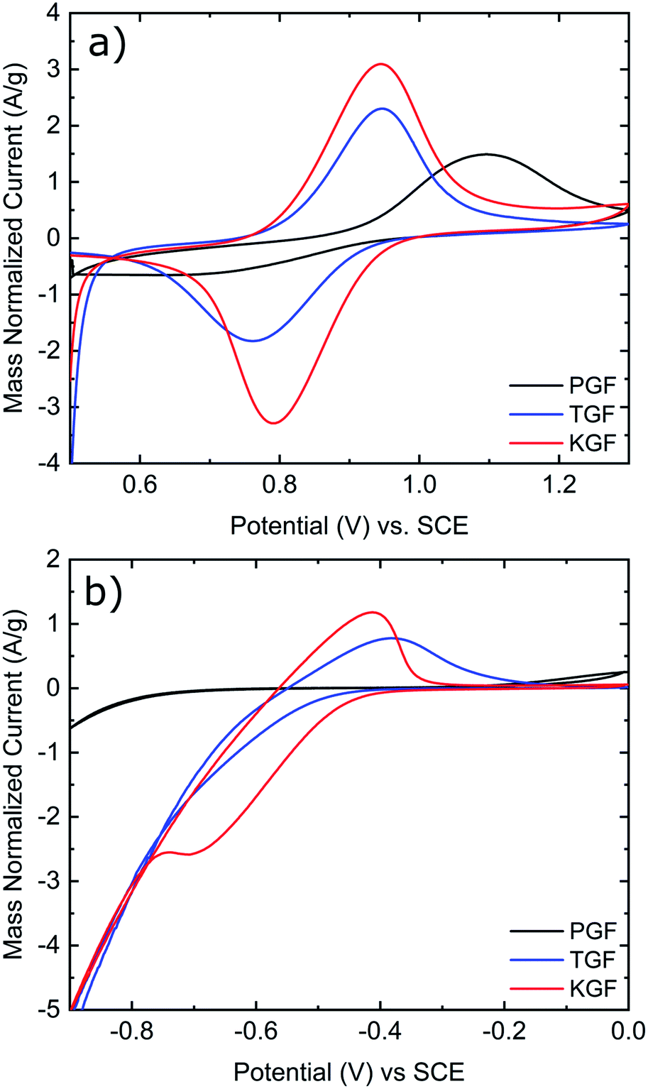 | ||
| Fig. 5 (a) Cyclic voltammograms of P-GF, T-GF, and K-GF electrodes in the positive electrolyte. (b) Cyclic voltammograms of P-GF, T-GF, and K-GF electrodes in the negative electrolyte. CV was conducted at 5 mV s−1 vs. SCE at room temperature and normalized by the mass of the electrode. Electrolyte composition for the positive electrolyte is 1:1 ratio 0.1 M VO2+:VO2+ in 2 M H2SO4 with 100 mM H3PO4. Electrolyte composition for the negative electrolyte is 1:1 ratio 0.1 M V3+:V2+ in 2 M H2SO4 with 100 mM H3PO4. | ||
Electrochemical impedance spectroscopy (EIS) was performed to assess the impact of the electrode treatments on the kinetic behaviour in a single cell environment. The resulting Nyquist plots are shown in Fig. S8.† The charge transfer resistance (RCT) is calculated as the difference between the high frequency resistance (HFR) and low frequency resistance (LFR) of the equivalent circuit model in Fig. S9† and extracted values are shown in Table S2.† For the P-GF electrode, RCT is determined to be 90.50 Ω cm2. For the T-GF electrode significantly reduced values of 0.88 Ω cm2 are obtained. The large RCT value for the P-GF electrode indicates a substantial kinetic resistance which would prevent this electrode from functioning efficiently inside the battery. The T-GF demonstrates a substantial improvement in RCT compared to the P-GF electrode, but it is not comparable to the K-GF electrode which exhibits the lowest RCT value of 0.53 Ω cm2.
Cycling results are shown in Fig. 6. The battery was cycled at multiple current densities to assess the performance of all three electrodes under different loads. The P-GF sample was not capable of completing any cycling experiments with current densities greater than 40 mA cm−2, which is due to its poor half-cell electrochemical performance (Fig. 5), its hydrophobic behaviour during contact angle analysis (Fig. S4†) and its large RCT value obtained by EIS (Fig. S8†). The T-GF electrode was capable of a maximum cycling rate of 200 mA cm−2. Coulombic efficiency (CE) values of >97% were obtained for all current densities tested. Energy efficiency (EE) values show instability during cycling with on average 5% decay in EE at each current density tested. The T-GF electrode started with low EE values (70%) for the lowest current density tested (100 mA cm−2). This poor performance continues to decline as the current density increased, with EE values decreasing below 60% during cycling at 200 mA cm−2. Voltage efficiency (VE) values mirror the behaviour seen in the EE. The K-GF electrode achieved a very high cycling current density of 400 mA cm−2. For all current densities tested, the CE remained >97% with values > 98% while cycling higher than 300 mA cm−2. At 100 mA cm−2 EE values are stable at 85%, at 200 mA cm−2 EE values are 77% and at 400 mA cm−2 the K-GF electrodes were operating at a stable 61% EE. The voltage–capacity plot in Fig. 6b demonstrates how the increased kinetic polarization, caused by the larger RCT of the T-GF electrode in Fig. S8,† affects the maximum usable capacity of the system. The T-GF electrode exhibits significant polarization as seen by the starting potentials for the charging and discharge curves (dashed lines) in Fig. 6b, resulting in low system capacity. To assess the stability of the K-GF electrodes, the system was cycled 30 times at a high current density of 400 mA cm−2 (Fig. 7a). The K-GF electrode exhibited a remarkable stability in performance with stable CE values of 98%, EE values of 60% and VE values of 61%. From cycles 1–10, EE dropped about 0.5% to 59.5%, where it stabilized throughout the rest of the test within cycles 11–30. The stable EE performance of the system is in line with the stable cell HFR values around 440 mOhm cm2 shown in Fig. 7b and confirms stability of the treatment as well as other cell properties such as membrane or electrode conductivity over the cycling experiment. To assess the contribution of the electrodes to cell HFR, the battery was assembled without the membrane included. A current sweep test was performed and from the generated I–V plot, the slope was isolated and the electrode resistance was extracted using Ohms' Law. The contribution of the K-GF electrodes at a compression of 60% was 87 mOhm (348 mOhm cm2). The contribution of the P-GF and T-GF electrodes at 60% compression were 49 mOhm (196 mOhm cm2) and 45 mOhm (180 mOhm cm2) respectively. The high value of the K-GF electrode is attributed to 79% of the observed cell HFR values displayed in Fig. 7b. The increased resistance can be linked to the substantial increase in surface-based oxygen functional groups and surface defects which decrease electrical conductivity. Therefore, in order to improve the cell HFR, the electrode thickness must be decreased. Successfully decreasing the cell HFR would allow current densities > 400 mA cm−2 to be achieved while also increasing EE and VE values for lower current densities. A recent report by Jiang et al.45 demonstrated how a VRFB, that has undergone extensive optimisation of all essential cell components, is capable of reaching a maximum current density of 1 A cm−2 while maintaining an EE of 70%. As this article reports to our knowledge battery data amongst the best VRFB performances in literature, it can be used as reference to the efficiency values reported in this work: comparing our work in medium current densities of 200–300 mA cm−2, Jiang et al. obtained EE values of 76%, 72% and 68% when cycling at 200 mA cm−2, 250 mA cm−2 and 300 mA cm−2, respectively, when using a Nafion 212 membrane which is slightly worse than EE values obtained in this work of 77.5%, 74% and 70%. This confirms the high efficiency of the herein reported electrode treatment.
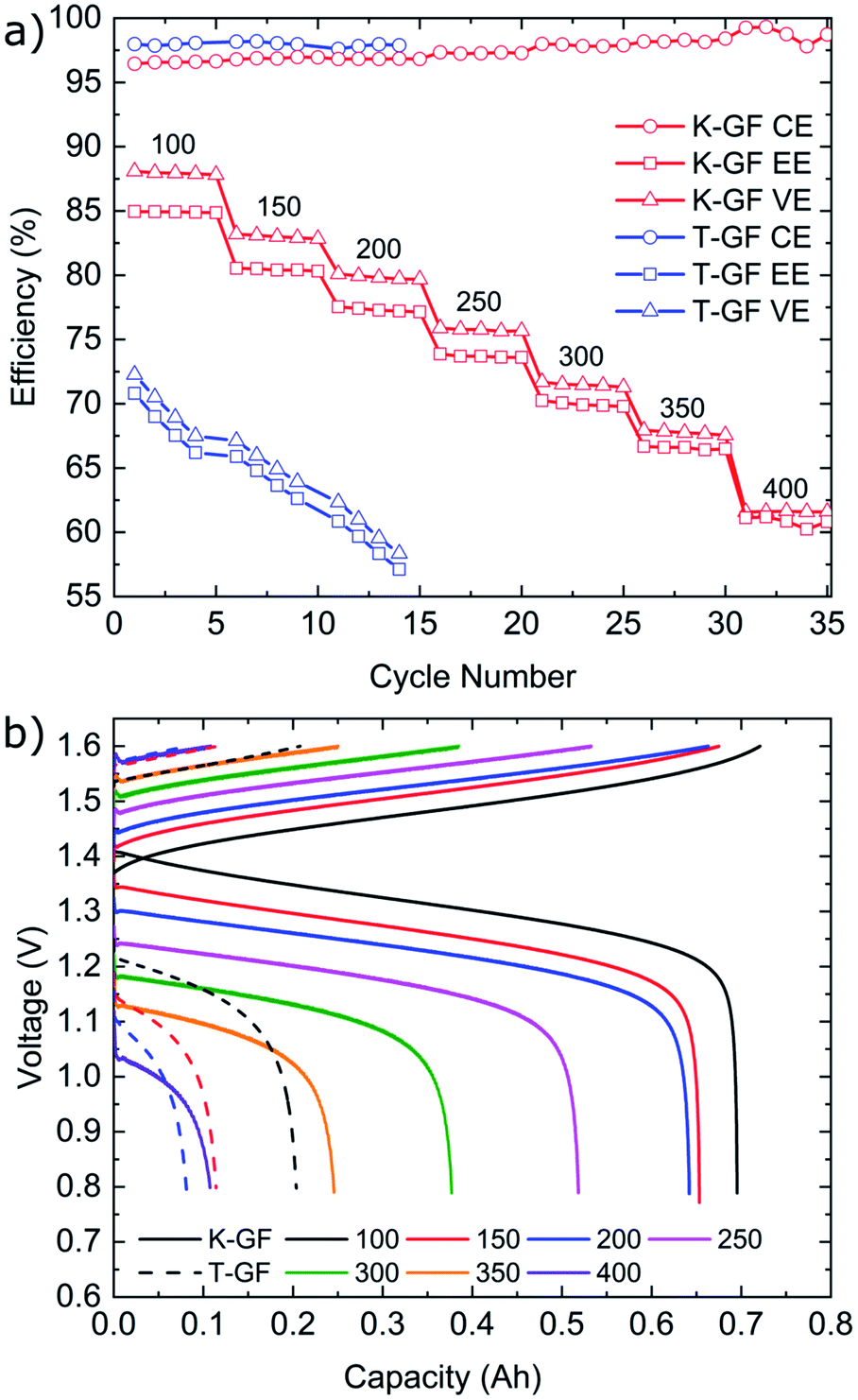 | ||
| Fig. 6 (a) CE, EE and VE values of the T-GF and K-GF electrodes after cycling at multiple current densities from 100–400 mA cm−2 in 1.6 M vanadium with 2 M H2SO4 and 100 mM H3PO4. The P-GF electrode was unable to cycle at current densities higher than 40 mA cm−2 and was therefore not included in this figure. (b) Voltage–capacity plot of the first cycle at each current density for the K-GF (solid) and T-GF (dashed) electrodes. | ||
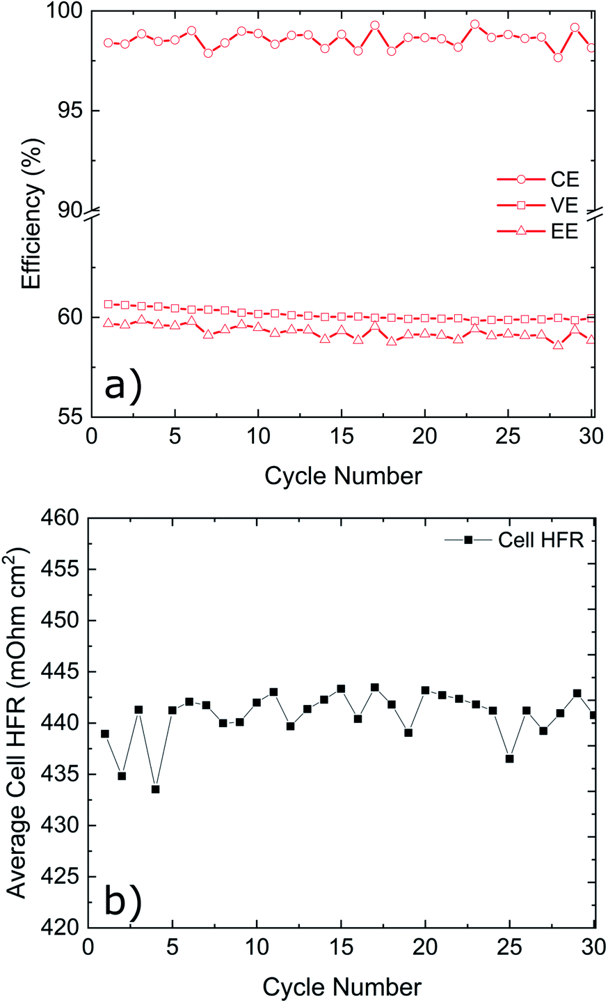 | ||
| Fig. 7 K-GF electrode cycling at 400 mA cm−2 for 30 cycles. (a) CE, EE and VE values for the K-GF electrode cycled at 400 mA cm−2 for 30 cycles. (b) Average cell HFR values of the system during cycling. | ||
Conclusion
In this work we report an acidified permanganate activation procedure of Rayon-based electrodes which is rapid (1 hour) and yields high performance electrodes for use in vanadium redox flow batteries. In comparison to pristine (P-GF) and thermally (T-GF) activated electrodes, acidified permanganate activated electrodes (K-GF) show numerous physical and electrochemical improvements. The activation process results in increased BET surface area of 9.93 m2 g−1 compared to 0.74 m2 g−1 for the reference (P-GF). Graphitic structural disorder, as measured by Raman, is increased to 1.24 ± 0.07 compared to 1.20 ± 0.12 (T-GF) and 0.92 ± 0.13 (P-GF). Half-cell measurements show increased reversibility and increased peak currents for both the positive and negative redox couples for K-GF felts. In contrast to the employed P-GF and T-GF electrodes, the K-GF electrode was the only electrode capable of separating the V2+ reduction reaction from the HER. The K-GF electrode showed therefore remarkable electrochemical performance and reached a maximum cycling rate of 400 mA cm−2 with coulombic efficiencies > 98% for rates higher than 300 mA cm−2. Energy efficiency remained over 80% when cycling at 150 mA cm−2 and dropped to 60% when cycling at 400 mA cm−2. Multiple cycles at 400 mA cm−2 revealed promising system stability with EE stabilizing at about 60% and a stable cell HFR of about 440 ± 5 mOhm cm2. These preliminary tests indicate promising stability of the K-GF electrodes when exposed to the harsh environment of the electrolyte during the tested timeframe. For future work, a comprehensive aging study utilizing longer cycling times and extensive post-cycling surface characterization should be performed. In addition, further analysis of chemically activated electrode felts is required to further understand the underlying activation mechanisms compared to thermal activation of electrode felts.Further room for improvement of the electrodes was identified as a large proportion of cell's high frequency resistance stems from the electrodes (348 mOhm cm2). The increase in electrode resistance can be linked to the increase in surface oxygen content as identified by XPS (5.6% for the P-GF to 25% for the K-GF). Therefore, a straightforward next step in battery development is an optimized ratio between the application of the herein reported treatment with a minimized electrode thickness to combine high electrochemical reversibility and low electrical cell resistance for higher battery efficiency.
Conflicts of interest
There are no conflicts to declare.Acknowledgements
This work was funded by the German Federal Ministry of Education BMBF within the project NeutroSense (FKZ: 05K19VFA), the German Federal Ministry of Economy within the project NextRedox (FKZ: 03EI3018A) as well as by the Deutsche Forschungsgemeinschaft (DFG, German Research Foundation) under Germany's Excellence Strategy – EXC-2193/1 – 390951807 (livMatS). Siham Ouardi gratefully acknowledges the financial support of ExsAKt project (03B110102) of the Federal Ministry of Transport and Digital Infrastructure (BMVI). We thank Markus Knäbbeler-Buß for XPS measurements.References
- R. Ye, D. Henkensmeier, S. J. Yoon, Z. Huang, D. K. Kim, Z. Chang, S. Kim and R. Chen, Redox Flow Batteries for Energy Storage: A Technology Review, J. Electrochem. Energy Convers. Storage, 2017, 15, 010801–010801-21 CrossRef.
- A. Z. Weber, M. M. Mench, J. P. Meyers, P. N. Ross, J. T. Gostick and Q. Liu, Redox flow batteries: a review, J. Appl. Electrochem., 2011, 41, 1137–1164 CrossRef CAS.
- H. Zhang, X. Li and J. Zhang, Redox Flow Batteries: Fundamentals and Applications, CRC Press, 2017 Search PubMed.
- S. P. Badwal, S. S. Giddey, C. Munnings, A. I. Bhatt and A. F. Hollenkamp, Emerging electrochemical energy conversion and storage technologies, Front. Chem., 2014, 2, 79 Search PubMed.
- S. Chu, Y. Cui and N. Liu, The path towards sustainable energy, Nat. Mater., 2017, 16, 16–22 CrossRef PubMed.
- K. J. Kim, M.-S. Park, Y.-J. Kim, J. H. Kim, S. X. Dou and M. Skyllas-Kazacos, A technology review of electrodes and reaction mechanisms in vanadium redox flow batteries, J. Mater. Chem. A, 2015, 3, 16913–16933 RSC.
- J. Langner, M. Bruns, D. Dixon, A. Nefedov, C. Wöll, F. Scheiba, H. Ehrenberg, C. Roth and J. Melke, Surface properties and graphitization of polyacrylonitrile based fiber electrodes affecting the negative half-cell reaction in vanadium redox flow batteries, J. Power Sources, 2016, 321, 210–218 CrossRef CAS.
- P. C. Ghimire, R. Schweiss, G. G. Scherer, T. M. Lim, N. Wai, A. Bhattarai and Q. Yan, Optimization of thermal oxidation of electrodes for the performance enhancement in all-vanadium redox flow batteries, Carbon, 2019, 155, 176–185 CrossRef CAS.
- Capital Cost Sensitivity Analysis of an All-Vanadium Redox-Flow Battery, ed. M. Zhang, M. Moore, J. S. Watson, T. A. Zawodzinski, and R. M. Counce, ECS, 2012 Search PubMed.
- A. Hassan, A. S. Haile, T. Tzedakis, H. A. Hansen and P. de Silva, The Role of Oxygenic Groups and sp3 Carbon Hybridization in Activated Graphite Electrodes for Vanadium Redox Flow Batteries, ChemSusChem, 2021 DOI:10.1002/cssc.202100966.
- S. Zhong, C. Padeste, M. Kazacos and M. Skyllas-Kazacos, Comparison of the physical, chemical and electrochemical properties of rayon- and polyacrylonitrile-based graphite felt electrodes, J. Power Sources, 1993, 45, 29–41 CrossRef CAS.
- H. Zhang, Y. Tan, J. Li and B. Xue, Studies on properties of rayon- and polyacrylonitrile-based graphite felt electrodes affecting Fe/Cr redox flow battery performance, Electrocatalysis, 2017, 248, 603–613 CAS.
- D. Dixon, D. J. Babu, J. Langner, M. Bruns, L. Pfaffmann, A. Bhaskar, J. J. Schneider, F. Scheiba and H. Ehrenberg, Effect of oxygen plasma treatment on the electrochemical performance of the rayon and polyacrylonitrile based carbon felt for the vanadium redox flow battery application, J. Power Sources, 2016, 332, 240–248 CrossRef CAS.
- L. Eifert, R. Banerjee, Z. Jusys and R. Zeis, Characterization of Carbon Felt Electrodes for Vanadium Redox Flow Batteries: Impact of Treatment Methods, J. Electrochem. Soc., 2018, 165, A2577–A2586 CrossRef CAS.
- A. Hassan and T. Tzedakis, Enhancement of the electrochemical activity of a commercial graphite felt for vanadium redox flow battery (VRFB), by chemical treatment with acidic solution of K2Cr2O7, J. Energy. Storage, 2019, 26, 100967 CrossRef.
- C. Gao, N. Wang, S. Peng, S. Liu, Y. Lei, X. Liang, S. Zeng and H. Zi, Influence of Fenton's reagent treatment on electrochemical properties of graphite felt for all vanadium redox flow battery, Electrocatalysis, 2013, 88, 193–202 CAS.
- S. Abbas, H. Lee, J. Hwang, A. Mehmood, H.-J. Shin, S. Mehboob, J.-Y. Lee and H. Y. Ha, A novel approach for forming carbon nanorods on the surface of carbon felt electrode by catalytic etching for high-performance vanadium redox flow battery, Carbon, 2018, 128, 31–37 CrossRef CAS.
- H. R. Jiang, W. Shyy, M. C. Wu, R. H. Zhang and T. S. Zhao, A bi-porous graphite felt electrode with enhanced surface area and catalytic activity for vanadium redox flow batteries, Appl. Energy, 2019, 233–234, 105–113 CAS.
- Y. Lv, J. Zhang, Z. Lv, C. Wu, Y. Liu, H. Wang, S. Lu and Y. Xiang, Enhanced electrochemical activity of carbon felt for V2+/V3+ redox reaction via combining KOH-etched pretreatment with uniform deposition of Bi nanoparticles, Electrocatalysis, 2017, 253, 78–84 CAS.
- Q. Deng, P. Huang, W.-X. Zhou, Q. Ma, N. Zhou, H. Xie, W. Ling, C.-J. Zhou, Y.-X. Yin, X.-W. Wu, X.-Y. Lu and Y.-G. Guo, A High-Performance Composite Electrode for Vanadium Redox Flow Batteries, Adv. Energy Mater., 2017, 7, 1700461 CrossRef.
- Z. Chen, Y. Gao, C. Zhang, X. Zeng and X. Wu, Surface-Wrinkle-Modified Graphite Felt with High Effectiveness for Vanadium Redox Flow Batteries, Adv. Electron. Mater., 2019, 5, 1900036 CrossRef.
- H. Wang, W. Ling, J. Chen, Z. Wang, X.-X. Zeng, Y. Hu, X. Wu, Q. Deng, G. Chen, Y. Wu and R. Holze, A three-dimensional conducting network of rGO-in-graphite-felt as electrode for vanadium redox flow batteries, Electrochem. Energy Technol., 2018, 4, 60–65 CAS.
- H. R. Jiang, W. Shyy, Y. X. Ren, R. H. Zhang and T. S. Zhao, A room-temperature activated graphite felt as the cost-effective, highly active and stable electrode for vanadium redox flow batteries, Appl. Energy, 2019, 233–234, 544–553 CrossRef CAS.
- J. Rouquerol, P. Llewellyn and F. Rouquerol, in Characterization of Porous Solids VII, ed. P. L. Llewellyn, F. Rodriquez-Reinoso, J. Rouqerol and N. Seaton, Elsevier, 2007, pp. 49–56 Search PubMed.
- N. Kausar, A. Mousa and M. Skyllas-Kazacos, The Effect of Additives on the High-Temperature Stability of the Vanadium Redox Flow Battery Positive Electrolytes, ChemElectroChem, 2016, 3, 276–282 CrossRef CAS.
- N. V. Roznyatovskaya, V. A. Roznyatovsky, C.-C. Höhne, M. Fühl, T. Gerber, M. Küttinger, J. Noack, P. Fischer, K. Pinkwart and J. Tübke, The role of phosphate additive in stabilization of sulphuric-acid-based vanadium(V) electrolyte for all-vanadium redox-flow batteries, 13th International Meeting on Lithium Batteries, 2017, vol. 363, pp. 234–243 Search PubMed.
- F. J. Oldenburg, M. Bon, D. Perego, D. Polino, T. Laino, L. Gubler and T. J. Schmidt, Revealing the role of phosphoric acid in all-vanadium redox flow batteries with DFT calculations and in situ analysis, Phys. Chem. Chem. Phys., 2018, 20, 23664–23673 RSC.
- T. Liu, X. Li, H. Nie, C. Xu and H. Zhang, Investigation on the effect of catalyst on the electrochemical performance of carbon felt and graphite felt for vanadium flow batteries, J. Power Sources, 2015, 286, 73–81 CrossRef CAS.
- R. M. McKenzie, The synthesis of birnessite, cryptomelane, and some other oxides and hydroxides of manganese, Mineral. Mag., 1971, 38, 493–502 CrossRef CAS.
- J. Melder, S. Mebs, P. A. Heizmann, R. Lang, H. Dau and P. Kurz, Carbon fibre paper coated by a layered manganese oxide: a nano-structured electrocatalyst for water-oxidation with high activity over a very wide pH range, J. Mater. Chem. A, 2019, 7, 25333–25346 RSC.
- J. Melder, W. L. Kwong, D. Shevela, J. Messinger and P. Kurz, Electrocatalytic Water Oxidation by MnOx/C: In Situ Catalyst Formation, Carbon Substrate Variations, and Direct O2/CO2 Monitoring by Membrane-Inlet Mass Spectrometry, ChemSusChem, 2017, 10, 4491–4502 CrossRef CAS PubMed.
- P. P. Brisebois and M. Siaj, Harvesting graphene oxide – years 1859 to 2019: a review of its structure, synthesis, properties and exfoliation, J. Mater. Chem. C, 2020, 8, 1517–1547 RSC.
- K. J. Kim, M.-S. Park, J.-H. Kim, U. Hwang, N. J. Lee, G. Jeong and Y.-J. Kim, Novel catalytic effects of Mn3O4 for all vanadium redox flow batteries, Chem. Commun., 2012, 48, 5455–5457 RSC.
- Z. He, L. Dai, S. Liu, L. Wang and C. Li, Mn3O4 anchored on carbon nanotubes as an electrode reaction catalyst of V(IV)/V(V) couple for vanadium redox flow batteries, Electrocatalysis, 2015, 176, 1434–1440 CAS.
- Q. Ma, Q. Deng, H. Sheng, W. Ling, H.-R. Wang, H.-W. Jiao, X.-W. Wu, W.-X. Zhou, X.-X. Zeng, Y.-X. Yin and Y.-G. Guo, High electro-catalytic graphite felt/MnO2 composite electrodes for vanadium redox flow batteries, Sci. China. Chem., 2018, 61, 732–738 CrossRef CAS.
- SGL Datasheet-SIGRACELL Battery Felts, https://www.sglcarbon.com/pdf/SGL-Datasheet-SIGRACELL-Battery-Felts-EN.pdf, accessed 17.02.21 Search PubMed.
- A. Merlen, J. G. Buijnsters and C. Pardanaud, A Guide to and Review of the Use of Multiwavelength Raman Spectroscopy for Characterizing Defective Aromatic Carbon Solids: from Graphene to Amorphous Carbons, Coatings, 2017, 7(10), 153 CrossRef.
- L. Bokobza, J.-L. Bruneel and M. Couzi, Raman Spectra of Carbon-Based Materials (from Graphite to Carbon Black) and of Some Silicone Composites, C, 2015, 1, 77–94 Search PubMed.
- S. Wang, X. Zhao, T. Cochell and A. Manthiram, Nitrogen-Doped Carbon Nanotube/Graphite Felts as Advanced Electrode Materials for Vanadium Redox Flow Batteries, J. Phys. Chem. Lett., 2012, 3, 2164–2167 CrossRef CAS PubMed.
- P. Mazúr, J. Mrlík, J. Beneš, J. Pocedič, J. Vrána, J. Dundálek and J. Kosek, Performance evaluation of thermally treated graphite felt electrodes for vanadium redox flow battery and their four-point single cell characterization, J. Power Sources, 2018, 380, 105–114 CrossRef.
- J. Melke, J. Martin, M. Bruns, P. Hügenell, A. Schökel, S. Montoya Isaza, F. Fink, P. Elsässer and A. Fischer, Investigating the Effect of Microstructure and Surface Functionalization of Mesoporous N-Doped Carbons on V4+/V5+ Kinetics, ACS Appl. Energy Mater., 2020, 3, 11627–11640 CrossRef CAS.
- A. C. Ferrari, Raman spectroscopy of graphene and graphite: Disorder, electron–phonon coupling, doping and nonadiabatic effects, Solid State Commun., 2007, 143, 47–57 CrossRef CAS.
- K. N. Kudin, B. Ozbas, H. C. Schniepp, R. K. Prud'homme, I. A. Aksay and R. Car, Raman Spectra of Graphite Oxide and Functionalized Graphene Sheets, Nano Lett., 2008, 8, 36–41 CrossRef CAS PubMed.
- R. Schweiss, C. Meiser and F. W. T. Goh, Steady-State Measurements of Vanadium Redox-Flow Batteries to Study Particular Influences of Carbon Felt Properties, ChemElectroChem, 2017, 4, 1969–1974 CrossRef CAS.
- H. R. Jiang, J. Sun, L. Wei, M. C. Wu, W. Shyy and T. S. Zhao, A high power density and long cycle life vanadium redox flow battery, Energy Storage Mater., 2020, 24, 529–540 CrossRef.
Footnotes |
| † Electronic supplementary information (ESI) available. See DOI: 10.1039/d1ra05808h |
| ‡ These authors contributed equally. |
| This journal is © The Royal Society of Chemistry 2021 |