DOI:
10.1039/C6RA17556B
(Paper)
RSC Adv., 2016,
6, 103822-103829
Low-temperature synthesis of mesoporous ZnTiO3–graphene composite for the removal of norfloxacin in aqueous solution
Received
9th July 2016
, Accepted 24th October 2016
First published on 26th October 2016
Abstract
A novel mesoporous perovskite-type ZnTiO3–graphene (MZT–GR) material was successfully fabricated via a two-step process in this paper. Initially, mesoporous ZnTiO3 (MZT) was prepared by an evaporation-induced self-assembly method using a polycarboxylate superplasticizer as a template at 500 °C, which was subsequently decorated on graphene using a hydrothermal method. The obtained products were characterized by thermogravimetric analysis (TG), Brunauer–Emmett–Teller analysis (BET), X-ray diffraction (XRD), scanning electron microscopy (SEM), high-resolution transmission electron microscopy (HRTEM), UV-visible diffuse reflectance spectroscopy (UV-visible DRS), and Raman spectroscopy. A series of photocatalysis experiments demonstrated that MZT–GR exhibited excellent photocatalytic performance. The degradation efficiency of norfloxacin reached 93% over MZT–GR composites under visible light irradiation for 60 min as compared with pure MZT (53%), which was attributed to MZT–GR's great adsorptivity of contaminants, enhanced light absorption and efficient charge separation properties collectively.
1. Introduction
In recent years, antibacterial agents and dye contaminants have caused extensive concern, as they have been detected in many surface waters.1,2 Norfloxacin (NOR) is a typical antibacterial agent, which is widely and largely used in the world.3 Synthetic dyes have also been diffusely used in several industries, such as paper printing and textile dyeing.2 Unfortunately, using general methods it is very hard to completely remove the NOR and dye from water bodies because of their stable properties and complex structures.4,5 Photocatalytic degradation of contaminants by semiconductor photocatalysts is a promising method for the purification of water bodies. Among the various photocatalytic materials researched, perovskite-based photocatalysts have some advantages.6
Recently, perovskite zinc titanate (ZnTiO3) has been utilized in many areas, such as gas sensing, painting, microwave dielectrics, and desulfurization of hot coal gases,7–10 because of its unique properties. However, pure ZnTiO3 is rarely prepared because it is very easy to generate Zn2TiO4 and rutile at high temperature.11,12 Mesoporous-structured materials possess large surface areas and many porous channels, which particularly contribute to adsorption and surface reaction of the contaminants. So mesoporous photocatalysts are very desirable in photocatalysis.13,14 Several mesoporous ZnTiO3 have been prepared using an evaporation-induced self-assembly method.15 However, polycarboxylate superplasticizer has never been used as a template for the fabrication of pure mesoporous perovskite ZnTiO3 to remove NOR, to the best of our knowledge.
Graphene, with a single layer structure, exhibits outstanding chemical and physical properties including chemical stability, high electrical conductivity, electron mobility, and high surface area.16,17 This provides a new insight into the fabrication of various novel nanocomposites. It has been reported that graphene merged with nanomaterials, such as ZnWO4@Fe3O4,18 Bi2MoO6,19 LaMnO3,20 ZnO,21 CaTiO3,22 or TiO2,23,24 showed enhanced photocatalytic performance. Therefore, we expect that the photocatalytic activity of MZT–GR nanocomposite could be improved as compared with pure MZT under UV-visible and visible light irradiation.
In this paper, a facile two-step process was used to synthesize MZT–GR. First, MZT was prepared by the evaporation-induced self-assembly (EISA) method; second, it was decorated onto graphene by a hydrothermal method. The influences of some parameters on the removal efficiency were investigated systematically, including graphene content, photocatalyst dosage, and light source. Reusability tests of MZT–GR nanocomposite were also investigated. NOR and methyl orange (MO) were chosen to assess the photocatalytic activity of the composites under UV-visible and visible light irradiation. The photocatalytic test results show that the removal performance of the MZT–GR composite is improved, which is attributed to its great adsorptivity of contaminants, enhanced light absorption, and efficient charge separation properties, collectively.
2. Experimental
2.1. Materials
All chemical reagents in this study were used without additional purification. The polycarboxylate superplasticizer (Fig. 1) (Mav = 18![[thin space (1/6-em)]](https://www.rsc.org/images/entities/char_2009.gif) 000) used as a template was produced and supplied by Hunan Ming Huang Technology Development Co., Ltd. Zn(NO3)2·6H2O was purchased from Shantou Xilong Chemical Reagent Co., Ltd. Tetra-n-butyl titanate and graphite powder were purchased from Sinopharm Chemical Reagent Co., Ltd.
000) used as a template was produced and supplied by Hunan Ming Huang Technology Development Co., Ltd. Zn(NO3)2·6H2O was purchased from Shantou Xilong Chemical Reagent Co., Ltd. Tetra-n-butyl titanate and graphite powder were purchased from Sinopharm Chemical Reagent Co., Ltd.
 |
| | Fig. 1 Structure unit of polycarboxylate superplasticizer. | |
2.2. Synthesis method
2.2.1. Preparation of MZT. In the synthesis, initially 1.0551 g of tetra-n-butyl titanate was added to 10 ml of ethanol and stirred for 30 min to form a solution. Then, 0.9222 g of Zn(NO3)2·6H2O and 0.4 g of polycarboxylate superplasticizer were dissolved in 10 ml of ethanol and stirred for 30 min. This mixture was added to the above solution by vigorous stirring. After stirring for 6 h at room temperature, the homogeneous sol underwent solvent evaporation in an oven. After 24 h of aging at 40 °C, the gel product was dried. The precursor products were calcined at 500 °C for 2 h in air to remove the polycarboxylate superplasticizer template and yield MZT particles.
2.2.2. Preparation of MZT–GR. Graphite oxide was prepared by a modified Hummers method.25 5 g of graphite powder and 2 g of NaNO3 were put into 120 ml of concentrated H2SO4 under an ice bath with stirring, and then 15 g of KMnO4 was slowly poured into the above solution. Afterwards, the mixture was stirred at 35 °C for 2 h and then diluted with 600 ml of distilled water. Next, 10 ml of 30% H2O2 was added to the mixture. The as-obtained graphite oxide was repeatedly washed with distilled water until the mixture of pH was about 7. After the exfoliation by ultrasonication, a brown graphene oxide (GO) supernatant was obtained by centrifugation.The MZT–GR composites were prepared via a hydrothermal method. Briefly, a specific amount of GO (5 mg ml−1) was dispersed in a mixture of distilled water (45 ml) and ethanol (25 ml) by ultrasonic treatment, and 0.2 g of MZT was put into the above mixture and stirred for 2 h to shape a homogeneous suspension. The suspension was then maintained at 120 °C for 3 h in a 100 ml Teflon-sealed autoclave under stirring constantly. Finally, the MZT–GR composite was collected by filtration, rinsed by distilled water, and dried. We have prepared five samples, with initial graphene oxide contents of 5%, 9%, 17%, 23%, and 29%; they are marked as MZT–GR-2, MZT–GR-4, MZT–GR-8, MZT–GR-12, and MZT–GR-16, respectively.
2.3. Characterization
Thermogravimetric analysis (TGA) of MZT precursor powders and the polycarboxylate superplasticizer was conducted using a thermoanalyser (Henven HTG-1) to test the weight loss of the products in air atmosphere. The nitrogen adsorption and desorption isotherms at 77.35 K were measured on an Autosorb-6b apparatus from Quanta 105 Chrome Instruments. All XRD patterns were characterized by an X-ray diffractometer with Cu Kα radiation (Rigaku D/Max 2500). The microstructure of the samples was observed by a scanning electron microscope (Hitachi-S4800) and a high-resolution transmission electron microscopy instrument (JEM-3010). Raman spectra were preformed from a Raman spectrometer (Labram-010). UV-visible diffuse reflectance spectra were recorded on an UV-visible spectrophotometer (Cary 300).
2.4. Photoactivity evaluation
The photocatalytic performances were evaluated by the degradation of NOR and MO (as comparison) under a 300 W xenon lamp (CEL-HXUV300). The photocatalysts were added into 50 ml of NOR and MO aqueous solution. After stirring in the dark for 30 min, the suspension was exposed to the light source. In order to get only visible light (λ > 400 nm), a UV cutoff filter was placed in the light path. At every 10 min, 1–2 ml of sample was withdrawn and then filtered through a 0.22 μm nylon 66 membrane to remove photocatalysts for further analysis. The concentration of the solution was acquired using an UV-visible spectrophotometer (LabTech BlueStar Plus) to measure the absorbance of NOR (276 nm) and MO (465 nm). For the reusability test, the photocatalysts were collected by centrifugation and directly applied to the successive photocatalytic measurements.
3. Results and discussion
3.1. Basic features of MZT and polycarboxylate superplasticizer
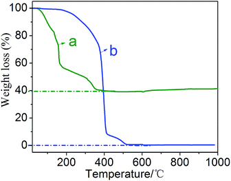
The TG curves of the MZT precursor powders and the polycarboxylate superplasticizer were measured in air atmosphere, as seen in Fig. 2. According to the report by Yan et al.,26 as shown in Fig. 2(a), the total weight loss of 60.77% can be mainly attributed to the evaporation of solvents, and the removal of organic matter, including the polycarboxylate superplasticizer template. The TG curve of polycarboxylate superplasticizer in Fig. 2(b) shows that the total weight loss of the polycarboxylate superplasticizer is 98.7% in the temperature range 20–500 °C, indicating that the burning of the polycarboxylate superplasticizer is almost completed at approximately 500 °C. The TG figure also illustrates that the fabrication of MZT at a relatively low calcining temperature of 500 °C may be due to the heat generated by the burning of the template.
 |
| | Fig. 2 The TG curves of (a) MZT precursor powders and (b) polycarboxylate superplasticizer. | |
In Fig. 3 we have demonstrated the N2 adsorption–desorption isotherms and pore size distribution curves of the MZT material and MZT–GR-8 composites. Fig. 3(a) exhibits a type-IV isotherm and a type-H2 hysteresis loop, suggesting that the MZT sample and MZT–GR-8 composites are all mesoporous-materials. Fig. 3(b) shows a very narrow pore size distribution of MZT and MZT–GR-8 samples by the Barrett–Joyner–Halenda (BJH) analysis and the average pore size is around 4 nm. The pore volume of MZT–GR-8 (0.11 cm3 g−1) decreased slightly after the introduction of graphene, when compared with that of pure MZT (0.15 cm3 g−1). The BET surface area of MZT–GR-8 (82.9 m2 g−1) was lower than pure MZT (110.8 m2 g−1), which is similar to those of other GR-based composites.27
 |
| | Fig. 3 (a) Nitrogen adsorption–desorption isotherms and (b) pore size distribution curves. | |
3.2. Characterization results
3.2.1. XRD analysis. The XRD patterns of MZT–GR-8 composites and MZT particles are shown in Fig. 4. All the diffraction peaks of MZT–GR-8 composites and bare MZT particles are identical, which can be indexed to the cubic perovskite ZnTiO3 structure28 (JCPDS card no. 39-0190). The result indicates that MZT was successfully formed in grapheme matrix and the structure of MZT in the composite did not change after combined with graphene.
 |
| | Fig. 4 XRD patterns of MZT particles and MZT–GR-8 composites. | |
3.2.2. SEM analysis. The morphology of samples was characterized with SEM and SEM images in Fig. 5(a) and (b) show MTZ is an aggregate of tiny spherical particles. Insteadly, bulk materials were obtained for preparation of MZT–GR-8 nanocomposites as shown in Fig. 5(c) and (d), where MZT nanoparticles were attached on the graphene surface.
 |
| | Fig. 5 SEM images of (a and b) MZT particles and (c and d) MZT–GR-8 composites. | |
3.2.3. HRTEM analysis. HRTEM images of MZT material and MZT–GR-8 composites are shown in Fig. 6. As seen from Fig. 6(a), these mesopores are chaotic. Fig. 6(b) shows that the MZT particles possess a lattice spacing of 0.25 nm, agreeing well with the value for the (311) plane of cubic ZnTiO3. In Fig. 6(c), the MZT particles and graphene nanosheets are clearly observed, which suggests that MZT materials have been intimately attached on the graphene supports. Fig. 6(d) shows the lattice structure of the MZT particles in the MZT–GR-8 is the same with that of pure MZT material.
 |
| | Fig. 6 HRTEM images of (a and b) MZT particles and (c and d) MZT–GR-8 composites. | |
3.2.4. Raman analysis. Fig. 7 shows the Raman spectra of MZT, GO, and MZT–GR-8. Raman spectroscopy is a very persuasive measurement to characterize carbon-based material.29 The Raman peaks appearing at approximately 514 and 227 cm−1 are ascribed to the ν1(TO) and ν4(LO), respectively, which are the characteristic peaks of the cubic phase28 present in the MZT and MZT–GR-8 samples. The other two peaks at 1311 (D peak) and 1595 cm−1 (G peak) are attributed to graphene30 in the Raman spectrum of MZT–GR-8. Fig. 7 also shows two typical Raman features of GO to detect the reduction of GO to graphene during the hydrothermal reaction. This result indicates that GO is reduced to graphene and MZT–GR-8 is successfully prepared.
 |
| | Fig. 7 Raman spectra of MZT, GO and MZT–GR-8 samples. | |
3.2.5. UV-visible DRS analysis. Fig. 8 shows the UV-visible DRS spectra of the MZT particles and MZT–GR-8 composites. When compared with the pure MZT, the MZT–GR-8 nanocomposites showed almost the same absorbance edge, but the absorbance intensity increased in the entire visible region. This may be due to the presence of graphene in the MZT–GR-8 composites.
 |
| | Fig. 8 UV-visible DRS spectra of (a) MZT particles and (b) MZT–GR-8 composites. | |
3.3. Photocatalytic performance
3.3.1. Effect of graphene content. Fig. 9 shows the photodegradation of NOR using MZT–GR photocatalysts with different graphene content under UV-visible light. It exhibits that the photocatalytic activity was improved for all MZT–GR samples, compared with that of the bare MZT photocatalyst. The inset of Fig. 9 clearly shows that the photocatalytic performance of MZT–GR is not improved invariably with the increase of graphene content. The photocatalytic activity of MZT–GR-8 composite is optimal in all samples, which implies that a appropriate loading amount of graphene on the surface of MZT is around 17 wt%.
 |
| | Fig. 9 Effect of graphene content for the removal of NOR (experiment conditions: [NOR]0 = 10 mg L−1, catalyst = 0.4 g L−1, UV-visible irradiation, reaction time = 60 min). | |
3.3.2. Effect of photocatalyst dosage. The impact of MZT–GR-8 dosage was investigated as shown in Fig. 10. It notes that the removal efficiency heightens with the increment of MZT–GR-8 dosage and the optimal dosage of MZT–GR-8 is 0.4 g L−1.
 |
| | Fig. 10 Effect of MZT–GR-8 dosage on the removal of NOR (experiment conditions: [NOR]0 = 10 mg L−1, UV-visible irradiation, reaction time = 60 min). | |
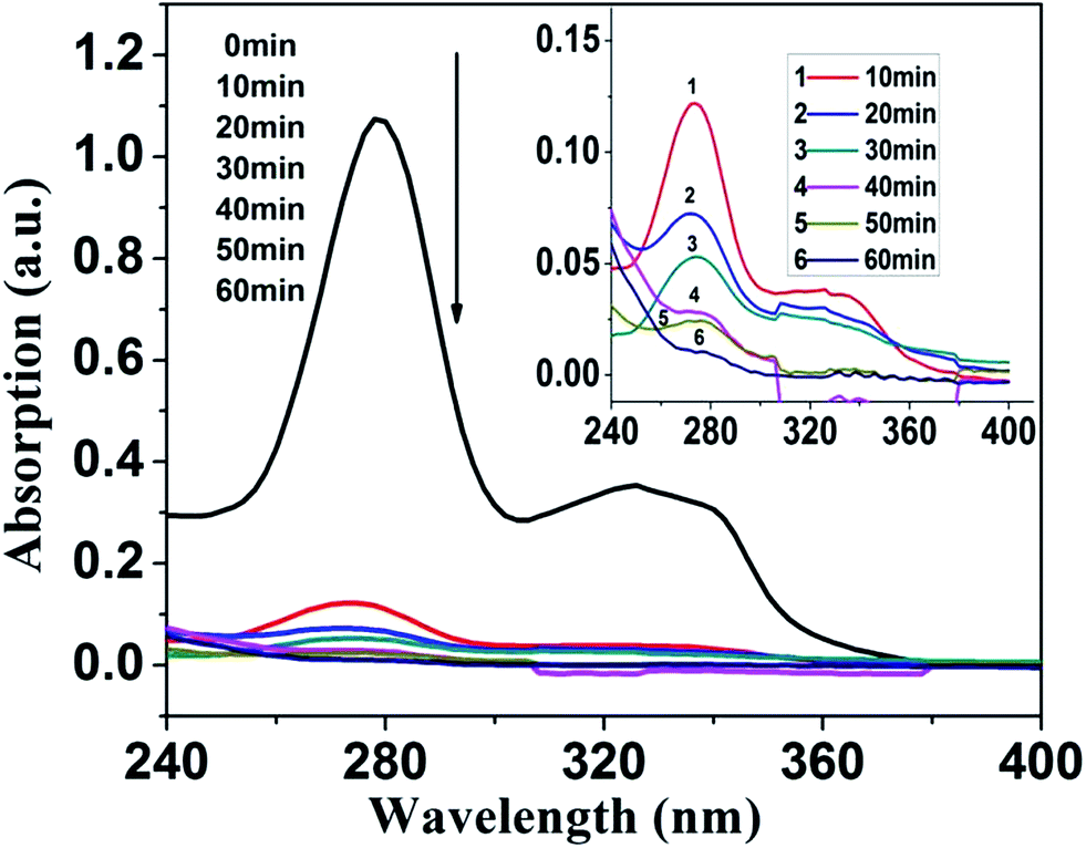
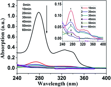
3.3.3. Removal performance of MZT–GR-8. Fig. 11 shows time-dependent absorption spectra of NOR suspension during the photocatalytic process. The characteristic absorption peaks of NOR are at around 276 and 326 nm, which is caused by the aromatic-ring and the quinolone nitrogen atom, respectively.31 The inset of Fig. 11 is a magnified view of Fig. 11 after 10 min; it notes clearly that the absorbance peaks corresponding to NOR have disappeared gradually with increasing the irradiation time. The result shows that the removal of NOR was effectual.
 |
| | Fig. 11 Removal performance of MZT–GR-8 for NOR (experiment conditions: [NOR]0 = 10 mg L−1, catalyst = 0.4 g L−1, UV-visible irradiation, reaction time = 60 min). | |
3.3.4. Reusability of MZT–GR-8 catalyst. To study the reusability of MZT–GR-8 catalyst, the catalyst was recycled by centrifugation from the reaction mixture and directly applied to the next cycle. Fig. 12 exhibits the adsorption percentage of NOR after 30 min in five cycles; it can be seen that the MZT–GR-8 composites exhibit 66%, 56%, 55%, 54%, and 52% adsorption toward NOR, respectively. This suggests that the composite has a relatively stable adsorption and the adsorption of NOR may be also removed in the photocatalytic process. The removal efficiencies of NOR over MZT–GR-8 in five consecutive cycles (Fig. 12) are 99%, 96%, 89%, 90%, and 88%, respectively, under UV-visible irradiation for 60 min. The results show that the reusability of MZT–GR-8 is still good enough after five cycles.
 |
| | Fig. 12 Reusability of MZT–GR-8 catalyst for NOR (experiment conditions: [NOR]0 = 10 mg L−1, catalyst = 0.4 g L−1, UV-visible irradiation, reaction time = 60 min). | |
3.3.5. Photocatalytic degradation of different contaminants. MZT–GR-8 composites were also applied for degradation of NOR and MO. Fig. 13(a) shows that NOR is almost completely removed after 40 min in the presence of the photocatalyst MZT–GR-8, which is comparable with that of the Degussa P25 formulation of TiO2. It can be also seen that MZT–GR-8 composites shown better photocatalytic performance than bare MZT. The removal efficiency of NOR using MZT was 88% in 40 min. However, when MZT was incorporated with graphene, the removal efficiency was 97%. Fig. 13(b) exhibits the photodegradation of MO under the same conditions; it notes that photocatalytic activity of the composites for MO decomposition is also excellent, but more suitable for NOR.
 |
| | Fig. 13 Removal efficiency versus irradiation time for the photodegradation of contaminants catalyzed MZT–GR-8 (▲) and P25 (▼) and MZT (●) and the blank without catalyst (■) under UV-visible irradiation: (a) NOR (b) MO. | |
3.3.6. Photodegradation of NOR under visible light (λ > 400 nm). Fig. 14(a) shows the photodegradation of NOR solution under visible light using MZT and MZT–GR-8 catalysts. A blank test, only exposed under visible light, can be almost ignored because its photodegradation efficiency is very low. The photocatalytic efficiency of MZT nanoparticles was only 53% after 60 min. However, nearly 93% of the NOR was removed after 60 min with MZT–GR-8 nanocomposites. The results show that MZT–GR-8 nanocomposites are able to enhance remarkably the photocatalytic performance under visible light. For purpose of further comparing their photocatalytic performance, Fig. 14(b) shows the plots of ln(C0/C) versus irradiation time t. The relevant kinetic parameters of removing NOR were presented in Table 1. These data imply that the photodegradation reaction of NOR follows pseudo-first-order kinetics. It was perfectly clear that MZT–GR-8 composites exhibited the higher photocatalytic performance than the pure MZT samples.
 |
| | Fig. 14 (a) Photodegradation of NOR under visible light (λ > 400 nm) over MZT–GR-8 (▲) and MZT (●) and the blank without catalyst (■); (b) relationship between ln(C0/C) and irradiation time of different samples. | |
Table 1 Kinetic parameters for degradation of NOR by different samples
| Sample |
Kinetic equation |
Ka (min−1) (λ > 400 nm) |
R2 |
| MZT |
ln(C0/C) = 0.00311t + 0.02536 |
0.00311 |
0.99083 |
| MZT–GR-8 |
ln(C0/C) = 0.02154t − 0.04464 |
0.02154 |
0.99606 |
4. Conclusions
In summary, MZT–GR nanocomposites were successfully synthesized using a facile two-step process. The photocatalytic results showed that the optimized condition is: a graphene content of 17 wt% (MZT–GR-8) and a catalyst dosage of 0.4 g L−1. The photocatalytic experiments revealed that MZT–GR-8 nanocomposites showed an enhanced photocatalytic performance toward the degradation of NOR and MO under UV-visible and visible light irradiation, when compared with pure MZT nanomaterials. The degradation efficiency of NOR for MZT–GR-8 (99.02%) was similar to that of the commercial catalyst P25 (99.83%) under UV-visible light irradiation, and higher (93%) than that of bare MZT particles (53%) under visible light irradiation for 60 min. The enhanced photocatalytic performance of MZT–GR-8 composites was attributed to its great adsorptivity of contaminants, increased light absorption, and efficient charge separation properties collectively. Moreover, the MZT–GR-8 nanocomposites also showed excellent performance in the aspect of repeated use. The performance tests above provide a powerful evidence for the actual application of MZT–GR-8 composites in wastewater treatment.
Acknowledgements
We gratefully thank the Natural Science Foundation of China (no. 50702020, 51402100 and 81171461), Natural Science Foundation of Hunan (no. 11JJ4013), Provincial Science & Technology Project of Hunan (no. 2013GK3155), the Youth 1000 Talent Program of China, interdisciplinary Research Program of Hunan University and the Fundamental Research Funds for the Central Universities.
References
- F. Baquero, J.-L. Martínez and R. Cantón, Curr. Opin. Biotechnol., 2008, 19, 260–265 CrossRef CAS PubMed.
- P. A. Carneiro, G. A. Umbuzeiro, D. P. Oliveira and M. V. B. Zanoni, J. Hazard. Mater., 2010, 174, 694–699 CrossRef CAS PubMed.
- X. Chang, M. T. Meyer, X. Liu, Q. Zhao, H. Chen, J.-A. Chen, Z. Qiu, L. Yang, J. Cao and W. Shu, Environ. Pollut., 2010, 158, 1444–1450 CrossRef CAS PubMed.
- I. M. Banat, P. Nigam, D. Singh and R. Marchant, Bioresour. Technol., 1996, 58, 217–227 CrossRef CAS.
- A. Nangia, F. Lam and C. T. Hung, Drug Dev. Ind. Pharm., 1991, 17, 681–694 CrossRef CAS.
- P. Kanhere and Z. Chen, Molecules, 2014, 19, 19995–20022 CrossRef CAS PubMed.
- H. Obayashi, Y. Sakurai and T. Gejo, J. Solid State Chem., 1976, 17, 299–303 CrossRef CAS.
- H. Kim, J. Byun and Y. Kim, Mater. Res. Bull., 1998, 33, 963–973 CrossRef CAS.
- S. Wu, J. Luo and S. Cao, J. Alloys Compd., 2010, 502, 147–152 CrossRef CAS.
- T. J. Lee, W. T. Kwon, W. C. Chang and J. C. Kim, Korean J. Chem. Eng., 1997, 14, 513–518 CrossRef CAS.
- M. Mohammadi and D. Fray, J. Eur. Ceram. Soc., 2010, 30, 947–961 CrossRef CAS.
- F. Dulln and D. Rase, J. Am. Ceram. Soc., 1960, 43, 125–131 CrossRef.
- X.-L. Wu, Y. Shi, S. Zhong, H. Lin and J.-R. Chen, Appl. Surf. Sci., 2016, 378, 80–86 CrossRef CAS.
- F. Zou, Z. Jiang, X. Qin, Y. Zhao, L. Jiang, J. Zhi, T. Xiao and P. P. Edwards, Chem. Commun., 2012, 48, 8514–8516 RSC.
- N. Pal, M. Paul and A. Bhaumik, Appl. Catal., A, 2011, 393, 153–160 CrossRef CAS.
- A. Gupta, T. Sakthivel and S. Seal, Prog. Mater. Sci., 2015, 73, 44–126 CrossRef CAS.
- K. S. Novoselov, V. Fal, L. Colombo, P. Gellert, M. Schwab and K. Kim, Nature, 2012, 490, 192–200 CrossRef CAS PubMed.
- M. M. J. Sadiq, U. S. Shenoy and D. K. Bhat, RSC Adv., 2016, 6, 61821–61829 RSC.
- F. Zhou, R. Shi and Y. Zhu, J. Mol. Catal. A: Chem., 2011, 340, 77–82 CrossRef CAS.
- J. Hu, J. Ma, L. Wang and H. Huang, J. Alloys Compd., 2014, 583, 539–545 CrossRef CAS.
- M. Ahmad, E. Ahmed, Z. Hong, J. Xu, N. Khalid, A. Elhissi and W. Ahmed, Appl. Surf. Sci., 2013, 274, 273–281 CrossRef CAS.
- T. Xian, H. Yang and Y. Huo, Phys. Scr., 2014, 89, 115801 CrossRef.
- W. Zhang, H. Guo, H. Sun and R.-C. Zeng, Appl. Surf. Sci., 2016, 382, 128–134 CrossRef CAS.
- N. Seifvand and E. Kowsari, RSC Adv., 2015, 5, 93706–93716 RSC.
- W. S. Hummers Jr and R. E. Offeman, J. Am. Chem. Soc., 1958, 80, 1339 CrossRef.
- L. Hou, Y.-D. Hou, M.-K. Zhu, J. Tang, J.-B. Liu, H. Wang and H. Yan, Mater. Lett., 2005, 59, 197–200 CrossRef CAS.
- K. Li, T. Chen, L. Yan, Y. Dai, Z. Huang, H. Guo, L. Jiang, X. Gao, J. Xiong and D. Song, Catal. Commun., 2012, 28, 196–201 CrossRef CAS.
- T. Surendar, S. Kumar and V. Shanker, Phys. Chem. Chem. Phys., 2014, 16, 728–735 RSC.
- A. C. Ferrari, Solid State Commun., 2007, 143, 47–57 CrossRef CAS.
- Z. Hua, X. Zhang, X. Bai, L. Lv, Z. Ye and X. Huang, J. Colloid Interface Sci., 2015, 450, 45–53 CrossRef CAS PubMed.
- S. Chen, Y. Li, R. Lü, J. Jiang, G. Zhang and P. Wang, Ind. Eng. Chem. Res., 2014, 53, 10775–10783 CrossRef CAS.
|
| This journal is © The Royal Society of Chemistry 2016 |
Click here to see how this site uses Cookies. View our privacy policy here.