
Graphene oxide and functionalized multi walled carbon nanotubes as epoxy curing agents: a novel synthetic approach to nanocomposites containing active nanostructured fillers
Vikas Patilab,
Robert V. Dennisb,
Tapan K. Routc,
Sarbajit Banerjeeb and
Ganapati D. Yadav *a
*a
aDepartment of Chemical Engineering, Institute of Chemical Technology, Mumbai-400019, India. E-mail: gd.yadav@ictmumbai.edu.in; gdyadav@yahoo.com
bDepartment of Chemistry, University at Buffalo, The State University of New York, Buffalo, New York 14260–3000, USA. E-mail: sb244@buffalo.edu
cResearch, Development, Technology & Innovation, Tata Steel Group, Jamshedpur-831007, India
First published on 22nd September 2014
Abstract
A novel synthetic approach is developed wherein graphene oxide and oxidized multiwalled carbon nanotubes are used as curing agents to induce cross-linking of an epoxy resin, thereby yielding a nanostructured epoxy composite with excellent dispersion of the carbon nanomaterials. This method allows for incorporation of up to 50 wt% of carbon nanomaterials within the polymeric matrix. The combination of covalent bonding and π–π interactions ensure excellent dispersibility of the nanomaterials within the polymeric matrix. These nanocomposites offer an alternative to the hazardous high-temperature fluorination and amine curing reactions that are usually required to formulate epoxy composite systems. Structural, mechanical, and morphological characterization of the composite material confirms the distribution, integrity, and potential to resist corrosion on a steel surface while also indicating the excellent adhesion and flexibility of the nanocomposite coatings.
Introduction
Hybrid materials formed by a combination of organic polymers and inorganic nanoparticles offer boundless potential for use in numerous applications owing to the possibility of realizing properties that are more than the sum of their parts. Hybrid nanomaterials can potentially be designed to exhibit enormous strength and a high density of interfaces.1 The active participation of the nanoparticles in influencing the functional properties of a nanocomposite relies on careful functionalization and the design of interfaces compatible with the host matrix.1,2 Fine tuning the compatibility between polymers and nanoparticles remains a formidable challenge, and one that requires careful tuning of parameters such as covalent bonds and non-covalent interactions on the surfaces of both nanoparticles and polymers. Hybrid materials are commonly plagued by the incompatibility between the inorganic filler and the organic matrix and such incompatibility often leads to failure. One strategy to mitigate such problems is to covalently bond the nanoparticles with the polymer matrix. In this article, we describe our progress towards developing a fully integrated functional coating system by compositing a mixture of oxidized multi-walled carbon nanotubes (MWCNTs) and graphene oxide within an epoxy matrix (henceforth denoted as MWCNTs@epoxy or graphene-oxide@epoxy). The chemical modification of MWCNTs and graphene and their subsequent incorporation in the epoxy matrix provides access to a stable, mechanically strong, and highly dispersed composite for surface coating applications.CNTs and graphene have attracted substantial interest as fillers within hybrid nanocomposite matrices and their functionalization serves to facilitate improved compatibility with the polymeric matrix. CNTs can sustain five to ten times the load of steel, and are characterized by a tensile strength of 50–100 GPa and an elastic modulus of 1–2 TPa, all while weighing 1/6th less than steel of the same volume.3–6 Graphene has a comparable elastic modulus and is one of the strongest materials known to man owing to its covalently bonded network of carbon atoms. Consequently, there is much interest in the use of CNTs and graphene as load-bearing fillers within nanocomposites with an emphasis on ensuring efficient load transfer between the matrix and the filler. Hybrid CNT/polymer and graphene/polymer composites where adequate dispersion and compatibility has been ensured also offer great promise as advanced coating materials.7–11
Depending upon the desired applications, graphene and CNTs have been variously modified. Indeed, surface functionalization is inevitable from oxidative routes used to obtain chemically derived graphene. As a scalable production route, chemically derived graphene has been prepared from graphite through an oxidation process that involves an intermediate called graphite oxide. Graphite oxide is an analogue of graphite where the distance between adjacent layers is increased as a result of the extensive functional group coverage on the basal planes and edges of individual graphene sheets. During the oxidation process, hydroxyl and epoxide functional groups are grafted onto the basal planes of graphene oxide, whereas the edges of the sheets are oxidized with carbonyl and carboxylic acid moieties.12–14 The increased abundance of hydrophilic functional groups on the surfaces of graphene oxide make it more hydrophilic in nature, which endows improved dispersibility in water.15–17 It has been observed that graphene oxide yields stable aqueous dispersions owing to complete exfoliation of individual graphene oxide layers.18 The oxidative approach thus offers a scalable route to stable and solution-processable aqueous dispersions of exfoliated graphene oxide for further incorporation within bulk nanocomposites and surface coatings. Graphene oxide has already been successfully incorporated as a filler for the formulation of coating materials, and has been shown to enhance the properties of the resulting nanocomposites by dint of its strength and high surface area.19–21
Despite the promising properties anticipated for CNT and graphene composites, full realization of the potential of these materials remains to be demonstrated. The use of CNTs in nanocomposites to date has been limited by their prohibitively high cost, challenges in processing, and impediments to dispersing the CNTs in host matrices. The latter in particular leads to failure owing to formation of phase-segregated domains. Ajayan et al. have demonstrated the preparation of epoxy composites by dispersing MWCNTs within an epoxy resin by the application of ultrasonic force.22 The incorporation of MWCNTs in the coating formulations induces a 125% enhancement of thermal conductivity and a 3.5× increase in Vickers' hardness upon the addition of just 2 wt% CNTs to the epoxy.23 At higher concentrations (exceeding 5 wt%), slip between nanotubes entangled in a bundle leads to failure and poor load transfer within the cured epoxy composite.24 Further, Sandler et al. have attempted to improve the dispersion of single-walled carbon nanotubes (SWCNTs) by combining ultrasonication with intense stirring. A slight improvement in dispersion has been evidenced but the composite is not homogenous across millimeter scales.25 While a continuous increase in the Young's modulus has been observed with respect to increase in concentration of SWNTs in the epoxy, the sliding of the SWCNTs within bundles and deformation of the ropes precludes effective load transfer and deleteriously impacts the mechanical strength of the composite.26 As an alternative approach, surfactants have also been used to improve the dispersion of SWCNTs in epoxy matrices;27 although the extent of dispersion appears to be substantially enhanced as compared to mechanical mixing alone, microscopic analysis still indicates in homogeneities in composition.28 In other work, fluorinated nanotubes have been reacted with diamines at high temperature with the latter serving to bridge the CNTs to the epoxy matrix.3,28 Composites are obtained through the simple dispersion of fluorinated CNTs within an epoxy/diamine mixture at high temperatures but the overall energy-intensive process requiring fluorination and the use of often toxic diamines is not the most attractive chemistry for technological translation.28,29 There is thus an urgent need to develop a next generation of CNT and graphene composite materials based on better synergy between the filler and the matrix and improved tunability of inter-particle spacing to more optimally harness the properties of CNTs and graphene.29 The composites developed here provide an attractive sustainable alternative to carcinogenic coating materials such as hexavalent chromates and to toxic resin curing processes requiring fluorination and diamines. To the best of our knowledge, the composites developed here represent the first implementation of MWCNTs and graphene oxide in such a surface coating application.
Experimental
Materials
MWCNTs were purchased from Cheap Tubes Inc. and graphite was acquired from Bay Carbon Inc. (Michigan, U.S.A.). MWCNTs and graphene were oxidized by the well-known Hummers' method and further used without purification.30 The epoxy resin used here was Araldite 506 [reaction product: bisphenol-A-(epichlorhydrin) and epoxy resin (average molecular weight = 700)] with an epoxide equivalent weight of 172–185 Da and viscosity of 500–700 cP (at 25 °C). Scheme 1 depicts the structure of the resin. This epoxy resin was used in combination with oxidized MWCNTs and graphene oxide, which serve as curing reagents and assist with cross-linking of the polymer as depicted in Scheme 2. Anhydrous THF was used as the solvent in this process. MWCNTs and graphene were oxidized using NaNO3, KMnO4, and H2SO4 in deionized water. Low-alloy steel for coating purposes was supplied by Tata Steel, Jamshedpur, India at a thickness of 0.67 mm and had the following nominal impurities: 0.1% C, 1.5% Mn, 0.2% Si, 40 ppm N, 0.01% P, 0.002% S, and 0.003% Ti. | ||
| Scheme 1 Structure of epoxy Araldite 506. | ||
 | ||
| Scheme 2 Depiction of the functionalization and subsequent curing reaction between graphene oxide/oxidized MWCNT and the epoxy resin. | ||
Functionalization of MWCNTs and graphene
Functionalization of MWCNTs and graphite was performed by the Hummers' method30 with some modifications. Briefly, 125 mL of H2SO4 was initially added and cooled in a round bottom flask, which was further charged with 2.0 g of natural flake graphite or MWCNTs in fine powder form. Subsequently, 1.0 g of NaNO3 was added to the flask. Further, 6.0 g of KMnO4 was added slowly, maintaining the temperature of the mixture around 20 °C. After complete addition of KMnO4, the reaction mixture was maintained at 35 °C for the next 30 min. Next, 100 mL of deionized water was added to the reaction mixture. During this addition, the temperature rose to 98 °C; the reaction was maintained at this temperature for the next 15 min. Subsequently, 150 mL of deionized water was added to the mixture followed by the addition of 20 mL of 30% hydrogen peroxide. The solution was mixed until the bubbling of gas ceased. Finally, the solution was filtered to obtain graphene oxide or oxidized MWCNTs and was washed with copious amounts of deionized water (until the filtrate had a pH of 7) and dried under vacuum overnight. Electron microscopy, Raman spectroscopy, thermogravimetric analysis, X-ray photoelectron spectroscopy, near-edge X-ray absorption fine structure (NEXAFS) spectroscopy, and scanning transmission X-ray microscopy characterization data for graphene oxide has been presented in our previous work.31–33Preparation of composite
The graphene oxide sheets or oxidized MWCNTs were dispersed first in anhydrous THF for 1 h using a Branson 5510 bath sonicator. After complete dispersion, the epoxy resin was subsequently added in appropriate proportion (ranging from 5 to 50 wt%) into the dispersion of graphene oxide/oxidized MWCNTs in THF under continuous sonication. Note that the graphene oxide and oxidized MWCNTs are used separately to form distinct composites. Further this process was performed at a constant bath temperature of 29 °C for 1 h.Surface coating of nanocomposite on low-alloy steel
The steel surface was initially cleaned using 2-propanol and further washed with ethanol. The prepared formulations of graphene-oxide/MWCNT@epoxy were applied through a standard wire-bar coating process. The applied formulations contained 5, 10, 25, and 50 wt% of the carbon nano-filler (graphene oxide or MWCNTs). The film thickness using the wire-bar applicator was found to be in the range of 5 to 7 μm. The coating was left uninterrupted overnight under ambient conditions at room temperature to complete the curing reaction.Characterization of structure and surface morphology
For quantitative determination of functional groups on graphene oxide and MWCNTs, 10 mg of graphene oxide and the oxidized MWCNTs were titrated with 0.0002 g mL−1 of NaOH solution using 5% phenolphthalein solution as the indicator.Raman spectroscopy and infrared reflection absorption (IRRA) spectroscopy were utilized to characterize the surface modification of MWCNTs and graphene oxide. Characterization of graphene-oxide/oxidized MWCNTs was performed by Raman spectroscopy using a Horiba Jobin Yvon Labram HR system with 514.5 nm laser excitation; IRRA was performed using a Bruker FTIR Vertex 70 instrument with a Hyperion 3000 microscope attachment. The surface morphology of graphene-oxide/MWCNTs@epoxy composite was investigated by utilizing scanning electron microscopy (SEM) on a Hitachi SU-70 instrument operated at an accelerating voltage of 20 kV. The dispersion of the composite was studied by transmission electron microscopy (TEM) using a JEOL-2010 instrument operated at 200 kV and 100 mA. Differential scanning calorimetry (DSC, Q200 TA Instruments) was performed under a flowing gaseous argon atmosphere. A temperature range from −90 to 300 °C was used to study the thermal characteristics of the prepared materials.
Corrosion testing of coating
The corrosion protection afforded by the composite coating was tested by immersing the coated samples in a 3.5% aqueous solution of NaCl. Visual observation of the surface at different time intervals was used to track red rust formation and evaluate corrosion inhibition.Mechanical testing of coating
The ASTM D2794 standard method was used to analyze impact resistance of the coatings (Precision Instrument Ltd. Pune, India). Upon rapid impact the coating was evaluated for any deleterious effects and deformation. Pencil hardness testing (Sheen Instruments, UK) was performed according to ASTM D3363, allowing for evaluation of film hardness. This method relies on drawing pencil leads of known hardness on coated substrates. ASTM D7027 was used for standardization of scratch hardness testing (Sheen Instruments, UK). The scratch hardness was analyzed by increasing the weight in an automatic scratch hardness tester. ASTM D3359 was used to determine the adhesion of coatings performed using a crosscut adhesion tester. A conical mandrel was used to determine the flexibility of the coated metal panel according to ASTM D522-93a. This test provides a measure of the resistance to cracking (flexibility) of a polymeric coating on a metal substrate.Results and discussion
Functionalization, dispersion of MWCNT/graphene, and curing of epoxy resin
Scheme 2 depicts the overall strategy deployed to disperse the carbon nanomaterials within the epoxy matrix. The functional groups on the surfaces of the MWCNTs and graphene oxide enable the carbon nanomaterials to function as curing agents for cross-linking of the polymer. Here, we have used Araldite 506 resin, which is commercially employed as a reactive epoxy resin. Araldite 506 is a slow curing epoxy resin that can be cured at room temperature simply by physical mixing owing to the presence of reactive functional groups. The ability to cure the resin at room temperature is particularly attractive from a scalability perspective. The agglomeration of the carbon nanomaterials and phase separation of the polymeric matrix and graphene-oxide/oxidized-MWCNTs, the two most formidable challenges for preparing functional nanocomposites, are sought to be mitigated by developing an in situ reaction between the resin and graphene-oxide/MWCNTs. Such an in situ polymerization approach provides long term stability of the nanostructured fillers against segregation even after several months. As illustrated in Scheme 2, the synthetic strategy adopted here combines the π–π interaction between the polymeric resin (with a backbone as depicted in Scheme 1) and the sidewalls of MWCNTs and remnant conjugated networks within graphene oxide while also directly bonding the functional groups of graphene oxide and oxidized MWCNTs.8,34,35 The proper mixing of graphene oxide/oxidizedMWCNTs and the uncured epoxy resin is imperative for achieving a quality dispersion of polymer and the nanomaterial in THF. The in situ polymerization is thus assisted by vigorous mixing facilitated by ultrasonication in a bath sonicator. The combination of π–π interactions and covalent bonding thus yields a system optimized for compatibility between the polymeric matrix and the nanostructured filler.Modifications of Hummers' method for functionalization of graphene/MWCNTs are commonly employed to introduce functional groups to the surfaces of these carbon nanomaterials. Based on a standard acid–base titration, 1 g of MWCNTs and graphene oxide are neutralized by 0.0055 and 0.0045 moles of NaOH, respectively, providing a measure of the concentration of acidic functional groups that are accessible for reaction with the epoxy resin. This also sets an upper limit for the amount of graphene oxide and oxidized MWCNTs that can be incorporated within the epoxy matrix; reacting equimolar amounts of the epoxy resin (ca. 1 g) with the oxidized MWCNTs and graphene oxide yields an approx 50 wt% stoichiometry. In case of 25, 10, and 5 wt% of MWCNTs, the reaction of acidic functional groups on graphene oxide and oxidized MWCNTs with the epoxide moiety of the resin as per Scheme 2 generates a hydroxyl species that can further propagate the cross-linking reaction. The degree of crosslinking is thus intimately linked to the loading of the carbon nanomaterials.
Functional groups introduced to surfaces of graphene and MWCNTs have been characterized by IRRA spectroscopy (Fig. 1).
 | ||
| Fig. 1 IRRA spectra of (a) epoxy without incorporation of carbon nanomaterials measured upon deposition on a steel surface, (b) 50 wt% graphene-oxide@epoxy, and (c) 50 wt% oxidized MWCNTs@epoxy. | ||
The data shows specific absorption peaks at 3455 and 3600 cm−1 for the resins incorporating graphene oxide and oxidized MWCNTs, respectively. These peaks at 3455 (Fig. 1b) and 3600 cm−1 (Fig. 1c) are attributed to –OH groups; both features are completely absent in the IRRA spectrum of the epoxy resin without incorporation of the carbon nanomaterials (Fig. 1a) and are clearly suggestive of hydroxyl species being generated as a result of the cross-linking of the resin with acidic functional groups on the carbon nanomaterials. In the epoxy resin, a C–H stretching absorption feature is observed at 2970 cm−1 but is diminished in intensity for the two composites of graphene-oxide/MWCNTs@epoxy likely due to the disruption of hydrogen bonding interactions. While sharp absorption bands have been observed in the fingerprint region for the composite materials, the epoxy resin by itself exhibits a broad envelope of peaks in this region. The spectral features observed at 830 cm−1 and 1145 cm−1 for the MWCNTs@epoxy composite correspond to C–O–C ether linkages and C–O stretches, respectively, whereas for graphene-oxide@epoxy, the absorption features at 860 and 1245 cm−1 are attributed to the C–O–O–C and C–O ether groups, respectively. Additional information is obtained by considering the bending vibrations observed in the IRRA spectra. As an example, long-chain aliphatic components such as polymers show strong methylene/methyl bands (1470 cm−1) and a weak methyl band (1380 cm−1) along with a methylene rocking mode at 725–720 cm−1. The splitting observed for the 1470 and 720 cm−1 bands suggest stabilization of a long-chain compound.36 No corresponding absorption bands are observed in the region between 720 and 725 cm−1. The peaks observed for the graphene-oxide@epoxy and MWCNTs@epoxy composites at 1495 and 1421 cm−1, respectively, may correspond to the carbonyl group36 generated during the functionalization process, which is retained as such upon covalent bonding to the epoxy matrix. A broad peak at 1980 cm−1 is observed only for the MWCNTs@epoxy sample, and might arise from isolated conjugated fragments upon disruption of extended π-networks due to oxidation. The IRRA spectra depicted in Fig. 1 thus illustrate that the graphene oxide and oxidized MWCNTs have indeed been covalently bonded to the epoxy matrix.
The observation of Raman D and G bands at 1345 and 1590 cm−1, respectively, confirm the sp2-hybridized frameworks of graphene oxide and MWCNTs (Fig. 2).37 From Fig. 2 it is worth noting that the peak positions of D and G bands are only subtly perturbed upon their incorporation within the epoxy matrix. However, the changes in the relative intensity ratios of the D and G bands are much more pronounced. The relative intensity of the G band is slightly diminished for the MWCNTs@epoxy composite as compared to MWCNTs alone. In the same vein, the D band becomes comparable in intensity to the G band for the graphene-oxide@epoxy composite showing a similar increase in intensity as observed for oxidized MWCNTs. The intensity of the 2D band observed for oxidized MWCNTs is not significantly modified. As expected upon extensive functionalization, and disruption of the π-conjugated network, the 2D band arising from a double resonance process is no longer as pronounced for graphene oxide. Fig. 2 suggests an increased extent of functionalization upon incorporation of MWCNTs and graphene oxide within the epoxy composite possibly as a result of free radical attack on the basal planes of graphene oxide and the sidewalls of the MWCNTs that leads to more extensive functionalization.
 | ||
| Fig. 2 Raman spectra of graphene oxide, oxidized MWCNTs, cured 50 wt% oxidized-MWCNTs@epoxy, and cured 50 wt% graphene-oxide@epoxy composites. | ||
Interfacial chemistry between graphene-oxide/oxidized MWCNTs and the epoxy matrix
As noted above, both π–π interactions and covalent bonding are involved in mediating the interfaces between the epoxy matrix and the nanostructured filler. Further corroboration of the good dispersion of the carbon nanomaterials in the epoxy resin has been derived from electron microscopy. SEM images in Fig. 3 show the quality dispersion of the graphene oxide and MWCNTs throughout the epoxy matrix upon application to the surface of low-alloy steel as a coating. | ||
| Fig. 3 (a) Top-view SEM image of a 50 wt% oxidized MWCNTs@epoxy composite coating onto low alloy steel, (b) cross-sectional SEM image of the 50 wt% oxidized MWCNTs@epoxy composite, (c) top-view SEM image of a 50 wt% graphene-oxide@epoxy composite coating on low alloy steel, and (d) cross-sectional SEM image of the 50 wt% graphene-oxide@epoxy composite. | ||
The cross-sectional SEM images of cryo-fractured samples depicted in Fig. 3a and b show protuberant oxidized MWCNTs that are embedded and well-dispersed in the epoxy matrix. These images clearly illustrate that the oxidized MWCNTs are well separated and no evidence of segregated MWCNT domains is observed. In some cases the hemispherical caps of the MWCNTs are discernible. These nanotubes also appear to be sheathed by a polymeric matrix. Fig. 3c shows the top-view of a graphene-oxide@epoxy coating on low-alloy steel depicting the rough surface of the coating with protruding graphene-oxide sheets. Analogously, Fig. 3d shows graphene oxide sheets dispersed within the epoxy matrix.
The TEM images in Fig. 4 allow for evaluation of the carbon-nanomaterial/filler interface. Fig. 4a and b indicate the excellent dispersion of disentangled oxidized MWCNTs in the epoxy resin with the latter high-magnification image indicating an oxidized MWCNT that is wrapped almost along the entirety of its length by the polymer matrix. Fig. 4c suggests a similar situation for graphene oxide wrapped with the epoxy polymer. The selected area electron diffraction pattern in Fig. 4d suggests the retention of some crystalline order for the embedded graphene oxide sheets despite the extensive functionalization.
 | ||
| Fig. 4 (a) TEM image of 50 wt% oxidized MWCNTs@epoxy composite; (b) high-magification TEM image of 50 wt% oxidized MWCNTs@epoxy composite; (c) TEM image of 50 wt% graphene-oxide@epoxy composite, and (d) selected area electron diffraction (SAED) pattern acquired for the 50 wt% graphene-oxide@epoxy composite. | ||
Fig. 1, 3 and 4 thus illustrate that the dual modality of covalent bonds (Scheme 2) and π–π interactions serve to render the nanostructured fillers compatible with the host matrix. Analogous chemistries have been used to obtain strong interfacial bonding and good dispersion of carbon fibers within polymeric matrices.38,39 However, to the best of our knowledge, this is the first example of using graphene oxide and oxidized MWCNTs as curing agents to obtain nanocomposites suitable for coating applications.
For CNT composites, both Zhu7et al. and Stevens40et al. have suggested that a high degree of dispersion and mechanical strength of nanostructured composites can be derived by using CNTs with a high degree of fuctionalization, for example, with sidewall fluorination. The high density of carboxylic acids and hydroxyl groups introduced here by Hummers' method can be viewed in the same light as facilitating chemical interactions with the epoxy resin matrix but without requiring diamines and high-temperature curing.7,40
DSC measurements have been further performed to examine the thermal properties of the prepared composites. Two distinct heating and cooling cycles have been performed in each instance in the temperature range between −90 and 300 °C.
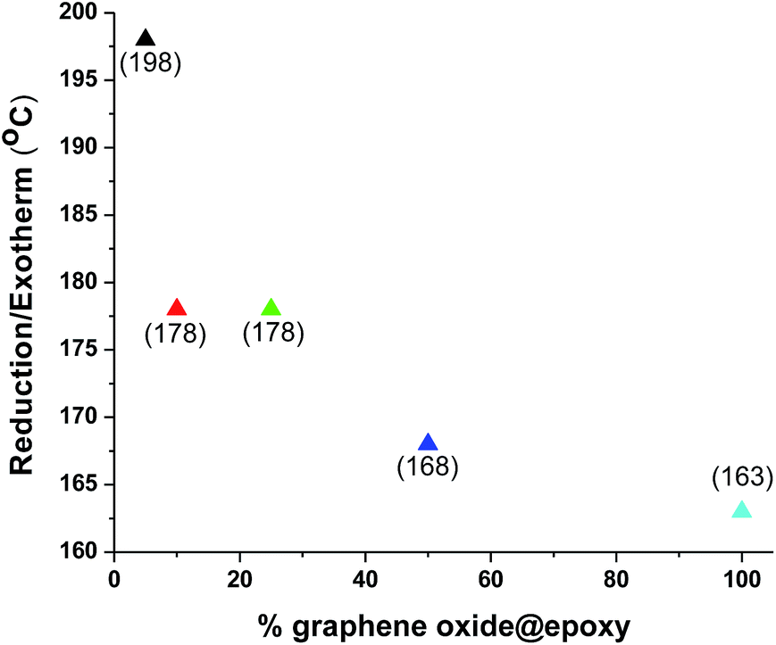
In the first heating cycle for graphene oxide, an irreversible endothermic peak is observed in the range between 86 and 138 °C and is attributed to elimination of water entrapped between the expanded galleries of graphene oxide (Fig. 5).41 The subsequent pronounced exothermic event at 163 °C in the first heating cycle has been ascribed to the reduction (defunctionalisation) of graphene oxide.41,42 These features are no longer observed in DSC profiles measured in the next cycle (not shown). Remarkably, the exothermic reduction temperature is appreciably modified in the nanocomposites (Fig. 5–8). The exothermic reduction of graphene oxide for 5, 10, 25, and 50 wt% epoxy composites is observed at 198, 178, 178, and 168 °C, respectively (Fig. 7 and 8). In other words, with increasing polymer:graphene-oxide ratio, the defunctionalization/reduction temperature for the latter filler is monotonically increased. Indeed, this observation is consistent with cross-linking of the pendant functional groups of graphene oxide with the epoxy resin since the formation of covalent bonds with the polymeric matrix likely renders the hydroxyl and carboxylic acid functional groups more stable and less amenable to defunctionalization as compared to graphene oxide alone.
 | ||
| Fig. 5 DSC analysis of graphene oxide, epoxy araldite resin, and composites: graphene-oxide@epoxy 50 wt%, graphene-oxide@epoxy 25 wt%. The exothermic peaks for graphene oxide, graphene oxide@epoxy 50 wt%, and graphene oxide@epoxy 25 wt% are observed at 163, 168, and 178 °C, respectively, whereas endothermic peaks are observed at 122, 132, and 135 °C, respectively. The Tg for epoxy araldite is estimated to be ca. −52 °C. | ||
 | ||
| Fig. 6 Evolution of the exothermic peak attributed to defunctionalization of graphene oxide as a function of the graphene oxide content in the epoxy composite. | ||
 | ||
| Fig. 7 DSC analysis of oxidized MWCNTs, epoxy araldite resin, oxidized MWCNTs@epoxy 50 wt%, oxidized MWCNTs@epoxy 25 wt%. The exothermic peaks for oxidized MWCNTs, oxidized MWCNTs@epoxy 50 wt%, and oxidized MWCNTs@epoxy 25 wt% were observed at 97, 192, and 204 °C respectively, whereas the endothermic peaks are observed at 135, 110, and 148 °C respectively. Tg for epoxy araldite was observed at −52 °C. | ||
 | ||
| Fig. 8 Evolution of the exothermic peak attributed to defunctionalization of oxidized MWCNTs as a function of the graphene oxide content in the epoxy composite. | ||
In the case of oxidized MWCNTs, the irreversible exothermic event corresponding to defunctionalization is observed at 97 °C. Analogously, incorporation within the epoxy matrix leads to a substantial increase in the stability of these functional groups as illustrated by Fig. 8. For the 5 wt% oxidized MWCNT@epoxy composite, the exotherm is shifted as high as 213 °C as a result of cross-linking.41,42 Given the low molecular weight of the resin, the Tg values are low even after cross-linking (in the range of −52 to −62 °C).
Corrosion inhibition endowed by nanocomposite coatings
Fig. 9 shows digital photographs of coated samples with 50, 25, 10, and 5 wt% loadings of graphene-oxide and MWCNTs exposed to a 3.5% aqueous solution of NaCl for up to 2160 h. The coating with 50 wt% graphene-oxide@epoxy displays strong resistance to corrosion and protects the surface effectively even after 2160 h exposure to salt solution; however, the samples with lower loadings of graphene oxide did not fare as well and appear to be significantly corroded (with evidence for red rust formation) after extensive exposure (2160 h) to the salt solution. The barrier protection properties provided by the 5 wt% graphene-oxide@epoxy loading is observed to be rather poor. On the contrary,the 50, 25, 10 wt% oxidized MWCNTs@epoxy resin coatings display strong resistance to corrosion and protect the surface effectively even after 2160 h exposure to salt solution; however, the samples with lower loading (5 wt% of oxidized-MWCNTs@epoxy) appear to be corroded after prolonged exposure (1080 h) to the salt solution. The poor performance of the 5 wt% composites may stem from inadequate cross-linking density as well as the relatively low amount of the electro-active filler. | ||
| Fig. 9 Digital photographs after exposure of coated low-alloy steel samples to a 3.5% aqueous solution of NaCl. The panels correspond to the following formulations: (a) 50 wt%, (b) 25 wt%, (c) 10 wt%, (d) 5 wt% graphene oxide embedded within the epoxy matrix; and (e) 50 wt%, (f) 25 wt%, (g) 10 wt%, and (h) 5 wt% oxidized MWCNTs embedded within the epoxy matrix compared to uncoated low-alloy steel. | ||
The corrosion inhibition noted here is comparable to previous work on graphene-oxide and MWCNT composites dispersed within poly(ether imide) matrices although larger loadings of fillers can be incorporated with this approach and the host matrix is expected to be considerably less expensive and thus better suited for large-area applications.8,9
Mechanical properties of nanocomposites
Epoxy composites with 5, 10, 25, 50 wt% graphene oxide/MWCNTs have been tested for impact resistance, pencil hardness, scratch hardness, adhesion, flexibility, and cracking resistance. The results are summarized in Table 1. All the samples appeared to meet the impact resistance and flexibility tests specified by ASTM standards for organic coatings. The pencil hardness has been determined to be 4H for all the coatings except 5 wt% graphene oxide@epoxy. Similarly,the coatings satisfy ASTM criteria for adhesion to steel surfaces. The adhesion of 5 wt% graphene-oxide@epoxy to low alloy steels was classified as 3B, whereas the rest of the coating samples have an adhesion rating of 4B (on a scale of 1B to 5B as specified by ASTM D3359). Furthermore all of the samples have been found to show good scratch hardness with an average value of 2.5 kg. The retention of excellent mechanical properties at high loadings of graphene oxide and MWCNTs is likely due to high density of functional groups on the fillers, which enables the formation of a dense cross-linked network of covalent bonds as per Scheme 2.| graphene-oxide@epoxy | MWCNTs@epoxy | |||||||
|---|---|---|---|---|---|---|---|---|
| Weight percent of graphene-oxide/MWCNTs@epoxy | 5 | 10 | 25 | 50 | 5 | 10 | 25 | 50 |
| Impact resistance (ASTM D2794) | Pass | Pass | Pass | Pass | Pass | Pass | Pass | Pass |
| Pencil hardness (ASTM D3363) | 4H | 4H | 4H | 3H | 4H | 4H | 4H | 4H |
| Flexibility (ASTM D522-93a) | Pass | Pass | Pass | Pass | Pass | Pass | Pass | Pass |
| Adhesion (ASTM D3359 | 3B | 4B | 4B | 4B | 4B | 4B | 4B | 4B |
| Scratch hardness (kg) (ASTM D7027) | 2.6 | 2.5 | 2.4 | 2.4 | 2.6 | 2.5 | 2.4 | 2.4 |
Conclusions
We demonstrate here the excellent dispersion and incorporation of graphene oxide and oxidized MWCNTs as active nano-filler components within an epoxy matrix, where the carbonaceous nanomaterials act to enhance the properties of the epoxy matrix while also initiating the curing reaction through covalent bonding. As reactive filler components, the nanomaterials have been successfully integrated within the core backbone of the polymeric matrix by utilizing covalent chemical modification. The functionalization of graphene oxide and MWCNTs and the additional driving force for mixing provided by π–π interactions allows for enhanced compatibility between the two disparate types of materials (carbon nanomaterials and polymeric matrix). The composite formulations allow for incorporation of up to 50 wt% nano-fillers into the polymer matrix without phase segregation. The synthetic route developed here allows for a sustainable alternative to the use of high-temperature amine curing agents and the need for performing corrosive side wall fluorination of MWCNTs. The prepared graphene-oxide@epoxy nanocomposites are shown to endow excellent corrosion inhibition properties to low alloy steels, which is in contrast to the MWCNTs@epoxy materials. Both sets of nanocomposites show excellent flexibility and reasonable adhesion on steel substrates. Future work will focus on examining the cure kinetics as a function of the concentration of carbon nanomaterials.Conflict of interest statement
The authors declare no conflict of interest.Acknowledgements
We gratefully acknowledge support from the Indo-US Science and Technology Forum, New Delhi for the Joint Centre “IUSSTF/JC-Thin film & Nanostructure Coatings/66-2010/2011-2012 among ICT Mumbai, SUNY Buffalo and Tata Steel, Jamshedpur. GDY gratefully acknowledges support from R. T. Mody Distinguished Professor Endowment and J. C. Bose National Fellowship, Govt of India.”References
- C. G. Granqvist, Sol. Energy Mater. Sol. Cells, 2012, 99, 166–175 CrossRef CAS PubMed.
- M. L. Zheludkevich, I. M. Salvado and M. G. S. Ferreira, J. Mater. Chem., 2005, 15, 5099–5111 RSC.
- S. Berber, Y.-K. Kwon and D. Tománek, Phys. Rev. Lett., 2000, 84, 4613–4616 CrossRef CAS.
- O. Lourie and H. D. Wagner, J. Mater. Res., 2011, 13, 2418–2422 CrossRef.
- D. A. Walters, L. M. Ericson, M. J. Casavant, J. Liu, D. T. Colbert, K. A. Smith and R. E. Smalley, Appl. Phys. Lett., 1999, 74, 3803–3805 CrossRef CAS PubMed.
- R. Andrews, D. Jacques, A. M. Rao, T. Rantell, F. Derbyshire, Y. Chen, J. Chen and R. C. Haddon, Appl. Phys. Lett., 1999, 75, 1329–1331 CrossRef CAS PubMed.
- J. Zhu, J. Kim, H. Peng, J. L. Margrave, V. N. Khabashesku and E. V. Barrera, Nano Lett., 2003, 3, 1107–1113 CrossRef CAS.
- R. V. Dennis, L. T. Viyannalage, A. V. Gaikwad, T. K. Rout and S. Banerjee, Am. Ceram. Soc. Bull., 2013, 92, 18–24 CAS.
- T. K. Rout, A. V. Gaikwad, V. Lee and S. Banerjee, J. Mater. Res., 2011, 26, 837–844 CrossRef CAS.
- N. Voevodin, V. Balbyshev, M. Khobaib and M. Donley, Prog. Org. Coat., 2003, 47, 416–423 CrossRef CAS.
- T. Ramanathan, A. A. Abdala, S. Stankovich, D. A. Dikin, M. Herrera-Alonso, R. D. Piner, D. H. Adamson, H. C. Schniepp, X. Chen, R. S. Ruoff, S. T. Nguyen, I. A. Aksay, R. K. Prud’Homme and L. C. Brinson, Nat. Nanotechnol., 2008, 3, 327–331 CrossRef CAS PubMed.
- H. He, J. Klinowski, M. Forster and A. Lerf, Chem. Phys. Lett., 1998, 287, 53–56 CrossRef CAS.
- A. Lerf, H. He, M. Forster and J. Klinowski, J. Phys. Chem. B, 1998, 102, 4477–4482 CrossRef CAS.
- L. R. De Jesus, R. V. Dennis, S. W. Depner, C. Jaye, D. A. Fischer and S. Banerjee, J. Phys. Chem. Lett., 2013, 4, 3144–3151 CrossRef CAS.
- M. Hirata, T. Gotou, S. Horiuchi, M. Fujiwara and M. Ohba, Carbon, 2004, 42, 2929–2937 CAS.
- M. Hirata, T. Gotou and M. Ohba, Carbon, 2005, 43, 503–510 CrossRef CAS PubMed.
- T. Szabó, A. Szeri and I. Dékány, Carbon, 2005, 43, 87–94 CrossRef PubMed.
- S. Stankovich, R. D. Piner, X. Chen, N. Wu, S. T. Nguyen and R. S. Ruoff, J. Mater. Chem., 2006, 16, 155–158 RSC.
- N. I. Kovtyukhova, P. J. Ollivier, B. R. Martin, T. E. Mallouk, S. A. Chizhik, E. V. Buzaneva and A. D. Gorchinskiy, Chem. Mater., 1999, 11, 771–778 CrossRef CAS.
- N. A. Kotov, I. Dekany and J. H. Fendler, Adv. Mater., 1996, 8, 637–641 CrossRef CAS.
- T. Cassagneau, F. Guérin and J. H. Fendler, Langmuir, 2000, 16, 7318–7324 CrossRef CAS.
- L. S. Schadler, S. C. Giannaris and P. M. Ajayan, Appl. Phys. Lett., 1998, 73, 3842–3844 CrossRef CAS PubMed.
- M. J. Biercuk, M. C. Llaguno, M. Radosavljevic, J. K. Hyun, A. T. Johnson and J. E. Fischer, Appl. Phys. Lett., 2002, 80, 2767–2769 CrossRef CAS PubMed.
- P. M. Ajayan, L. S. Schadler, C. Giannaris and A. Rubio, Adv. Mater., 2000, 12, 750–753 CrossRef CAS.
- J. Sandler, M. S. Shaffer, T. Prasse, W. Bauhofer, K. Schulte and A. Windle, Polymer, 1999, 40, 5967–5971 CrossRef CAS.
- L. Vaccarini, in AIP Conference Proceedings, AIP, 2000, vol. 544, pp. 521–525 Search PubMed.
- X. Gong, J. Liu, S. Baskaran, R. D. Voise and J. S. Young, Chem. Mater., 2000, 12, 1049–1052 CrossRef CAS.
- S. Spindler-Ranta and C. E. Bakis, in Proceedings of 47th international SAMPE symposium, 2002, pp. 1775–1787 Search PubMed.
- A. Bansal, H. Yang, C. Li, K. Cho, B. C. Benicewicz, S. K. Kumar and L. S. Schadler, Nat. Mater., 2005, 4, 693–698 CrossRef CAS PubMed.
- R. E. O. William and S. Hummers, J. Am. Chem. Soc., 1958, 80, 1339 CrossRef.
- R. V. Dennis, B. J. Schultz, C. Jaye, X. Wang, D. A. Fischer, A. N. Cartwright and S. Banerjee, J. Vac. Sci. Technol. B, 2013, 31, 041204 Search PubMed.
- V. Lee, R. V. Dennis, C. Jaye, B. J. Schultz, D. A. Fischer and S. Banerjee, J. Phys. Chem. C, 2012, 116, 20591–20599 CAS.
- V. Lee, R. V. Dennis, C. Jaye, X. Wang, D. A. Fischer, A. N. Cartwright and S. Banerjee, J. Vac. Sci. Technol. B, 2012, 30, 061206 Search PubMed.
- S. Kumar, L. L. Sun, S. Caceres, B. Li, W. Wood, A. Perugini, R. G. Maguire and W. H. Zhong, Nanotechnology, 2010, 21, 105702–105711 CrossRef CAS PubMed.
- K. E. Wise, C. Park, E. J. Siochi and J. S. Harrison, Chem. Phys. Lett., 2004, 391, 207–211 CrossRef CAS PubMed.
- J. Coates, Encycl. Anal. Chem., 2000, 10815–10837 Search PubMed.
- A. C. Ferrari, Solid State Commun., 2007, 143, 47–57 CrossRef CAS PubMed.
- C. Kozlowski and P. M. A. Sherwood, Carbon, 1987, 25, 751–760 CrossRef CAS.
- C. Jones, Compos. Sci. Technol., 1991, 42, 275–298 CrossRef CAS.
- J. L. Stevens, A. Y. Huang, H. Peng, I. W. Chiang, V. N. Khabashesku and J. L. Margrave, Nano Lett., 2003, 3, 331–336 CrossRef CAS.
- A. J. Glover, M. Cai, K. R. Overdeep, D. E. Kranbuehl and H. C. Schniepp, Macromolecules, 2011, 44, 9821–9829 CrossRef CAS.
- I. O. Huyal, U. Koldemir, T. Ozel, H. V. Demir and D. Tuncel, J. Mater. Chem., 2008, 18, 3568–3574 RSC.
| This journal is © The Royal Society of Chemistry 2014 |