DOI:
10.1039/C4RA09151E
(Paper)
RSC Adv., 2014,
4, 52871-52877
Influence of Al2O3 nanoparticles embedded-TiO2 nanofibers based photoanodes on photovoltaic performance of a dye sensitized solar cell
Received
23rd August 2014
, Accepted 2nd October 2014
First published on 3rd October 2014
Abstract
Different weight percentages (1, 3 and 5 wt%) of the Al2O3 nanoparticles (NPs) embedded TiO2 nanofibers (NFs) were prepared by the electrospinning technique. A mixture of titanium isopropoxide, acetic acid, Al2O3 NPs and PVP in ethanol were used. X-ray diffraction studies confirmed the formation of anatase and mixed phase (anatase/rutile) for the pure TiO2 NFs and Al2O3 NPs embedded TiO2 NFs, respectively. SEM and TEM studies showed the morphologies of Al2O3 NPs embedded TiO2 NFs and their average diameter was found to be ∼83 nm. The chemical composition of TiO2 NFs was confirmed by EDX analysis. The effects of Al2O3 NPs embedded TiO2 nanofibers on the adsorption of dye and the charge transfer resistances were studied using UV-vis spectroscopy and electrochemical AC-impedance studies. Dye sensitized solar cells were fabricated using different weight percentages of Al2O3 NPs embedded TiO2 NFs as photoanodes and Pt as counter electrode and 0.5 M 1-butyl-3-methylimidazolium iodide, 0.5 M LiI, 0.05 M I2, 0.5 M 4-tertbutylpyridine in acetonitrile as the electrolyte. Among the three photoanodes tried, the cell fabricated using 3 wt% of Al2O3 NPs embedded TiO2 NFs as photoanode had an improved photocurrent efficiency (PCE) of 36.2% compared to other similar systems in the literature. This might be due to an improvement in dye adsorption by the addition of a basic oxide (Al2O3) and also the formation of a rutile phase (15.7%), thereby retarding the charge recombinations inside the DSSC and in turn increasing the Voc and the Jsc of the cell.
1. Introduction
Dye sensitised solar cells (DSSCs) are presently considered to be a promising candidate to replace the traditional p–n junction solar cells, which harvest clean and inexhaustible energy of the sun and convert it into electricity. Low cost fabrication and better solar conversion efficiency are the key factors involved in attracting researchers for this 3rd generation solar cell.1–3 The most crucial part of a DSSC is the wide band gap semiconductor metal oxides, which perform two important roles as being carrier for dye molecules and a transporter for the injected electrons. It has been found that the performance of DSSC depends mostly on the photoanode material, because it influences both the photocurrent and the photovoltage of the solar cell. Among the various reported photoanode materials (TiO2, ZnO, SnO2, etc.), TiO2 is found to exhibit high power conversion efficiency owing to its unique optoelectronic properties.4–7 There are two ways to optimise DSSC photoanodes, which will give an optimal light to electricity conversion.
The first one is to enhance the charge transport and the other is minimizing charge recombination which can be achieved by changing the morphology, porosity and crystallinity of the photoanodes. One dimensional (1D) nanostructured materials, such as nanofibers, nanotubes, nanobelts, nanowires and nanorods, showed better electron transport properties compared to nanoparticles based DSSCs.8,9 In the case of one dimensional material, electron transport is faster because of the presence of lower grain boundaries, high connectivity and high surface area as observed in nanofibers. The nanofibers provide direct electric pathways to ensure rapid collection of charge carriers generated in the device.
The second one is to maximize the light harvesting capability of the device in the photoanode. This is done by using high surface area and high porosity, to adsorb maximum amount of dye. The nanofibers allow better filling of electrolyte in their pores, which improve the contact with the semiconductor and also help in regeneration of oxidized dyes, leading to high energy conversion efficiency.10,11
Surface modification of TiO2 can be done by thin insulating oxides, such as Y2O3, MgO, Nb2O5, ZnO and Al2O3, or using high band gap semiconductors to increase dye adsorption and thus to improve the photocurrent efficiency.12–16 This difference is ascribed to the more basic nature of insulating oxides as compared to TiO2, favouring the dye attachment through its carboxylic acid groups. The voltage and fill factor of the cell are strongly enhanced due to the suppression of electron back transfer from TiO2 to the redox electrolyte in the presence of the insulating oxide.
In the present investigation, we prepared for the first time, Al2O3 NPs embedded TiO2 NFs by an electrospinning technique and studied the influence of different wt% of Al2O3 NPs embedded TiO2 nanofibers on the photovoltaic performances of DSSC.
2. Experimental details
2.1 Preparation of Al2O3 NPs embedded TiO2 NFs
Different weight percentages (1, 3 and 5 wt%) of Al2O3 NPs embedded TiO2 NFs were prepared by an electrospinning technique (Fig. 1) using a precursor solution containing 0.01 M titanium(IV) isopropoxide (TiP, Aldrich) and 0.04 M acetic acid, different wt% of Al2O3 NPs, and 5 wt% polyvinylpyrrolidone (PVP: MW = 1![[thin space (1/6-em)]](https://www.rsc.org/images/entities/char_2009.gif) 300000, Sigma Aldrich) in ethanol. After stirring for 6 h, the solution was loaded into a syringe equipped with a 27G stainless steel needle. The spinning rate (0.5 mL min−1) was controlled using a syringe pump. The electric field of 15 kV was applied between a metal orifice and an electrically grounded flat collector. The collector was placed at 12 cm below the tip of the needle. The humidity level inside the electrospinning chamber was maintained below 35% at ∼25 °C. The electrospun nanofibrous mats were removed from the collector and calcinated in a muffle furnace (Technico, India) at an increasing temperature rate of 5 °C min−1 from 30 °C to 500 °C to get different wt% of Al2O3 NPs embedded TiO2 NFs.
300000, Sigma Aldrich) in ethanol. After stirring for 6 h, the solution was loaded into a syringe equipped with a 27G stainless steel needle. The spinning rate (0.5 mL min−1) was controlled using a syringe pump. The electric field of 15 kV was applied between a metal orifice and an electrically grounded flat collector. The collector was placed at 12 cm below the tip of the needle. The humidity level inside the electrospinning chamber was maintained below 35% at ∼25 °C. The electrospun nanofibrous mats were removed from the collector and calcinated in a muffle furnace (Technico, India) at an increasing temperature rate of 5 °C min−1 from 30 °C to 500 °C to get different wt% of Al2O3 NPs embedded TiO2 NFs.
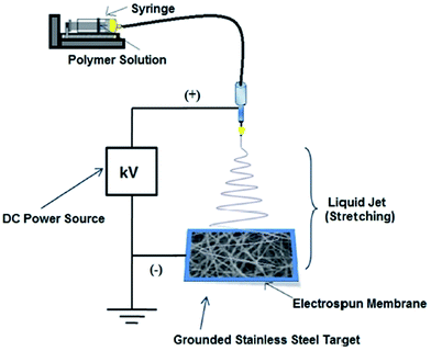 |
| | Fig. 1 Schematic illustration for electrospinning of Al2O3 NPs embedded TiO2 nanofibers. | |
2.2 Characterization
The structural properties of different weight percentages of Al2O3 NPs embedded TiO2 NFs were characterized by X-ray diffraction studies (Rigaku, Ultima IV) over a range of 2θ angles from 20° to 80°. The scanning electron microscopy (Hitachi, Model: S-4200) coupled with EDX (energy dispersive X-ray spectrometer) was employed to study surface morphology and the composition of different wt% of Al2O3 NPs embedded TiO2 NFs. The morphologies of Al2O3 NPs embedded TiO2 NFs were also probed using a transmission electron microscope (FEG-TEM, JSM-7600F). The absorption spectra were recorded by UV-vis spectrophotometer (PerkinElmer, Model: L-650) to study the influence of different wt% of Al2O3 NPs embedded TiO2 NFs on adsorption of the dye.
2.3 Fabrication of DSSC
FTO glass plates were cleaned with the help of detergent solution for 10 min, followed by cleansing in de-ionised water, acetone, and ethanol for 5 min each using an ultrasonic bath, and then they were dried in hot air. The pure TiO2 NFs and Al2O3 NPs embedded TiO2 NFs paste was prepared by the following method: as-prepared pure TiO2 NFs/Al2O3–TiO2 NFs with PVP were stirred vigorously for 15 minutes followed by addition of 2 mL ethanol and 0.3 mL acetylacetone to avoid aggregation. Subsequently, 0.2 mL acetic acid was added. Finally 4-octylphenol polyethoxylate (Triton X-100) was added to act as a dispensing agent followed by 1 mL ethanol. PVP was used to increase the viscosity and adhesion property of the paste and is easily decomposed at 450 °C during sintering.17 The paste were coated with a thickness of 10–12 μm on FTO glass plates by the doctor blade technique and sintered at 450 °C for 30 min. The active area of the cell was found to be 0.2 cm2. After cooling to 80 °C, the TiO2 electrodes were immersed into the purified 0.3 mM N719 dye solution [di-tetrabutyl ammonium cis-bis(isothiocyanato)bis(2,2′-bipyridyl-4,4′-dicarboxylato)ruthenium(II)] for 12 h at 30 °C.18 After completion of the dye adsorption, the films were rinsed with pure ethanol to remove the excess dye. In the counter electrode, a hole was drilled to later pass the electrolyte and subsequently cleaned in an ultrasonic bath with acetone and ethanol for 5 min. Then, a Pt paste was applied using the doctor blade technique, followed by sintering in a muffle furnace at 450 °C for 30 min. A 60 μm Surlyn spacer (SX 1170-60 from Solaronix) was sandwiched between the photoelectrode and the standard platinum coated FTO counter electrode. The space of each cell was filled with 0.5 M LiI, 0.05 M I2, 0.5 M 4-tertbutylpyridine in acetonitrile as the electrolyte by vacuum backfilling through the hole in the counter electrode. Finally, the hole was sealed with a hot-melt sheet and covered with a thin glass (0.1 mm).
2.4 Cell studies
The photovoltaic performances were measured using a computer controlled digital source meter. A Xe lamp with AM 1.5 filter (Oriel) was used to illuminate the DSSC at 100 mW cm−2. Electrochemical AC-impedance measurements were carried out at room temperature in the frequency range of 1 mHz to 100 kHz with the AC amplitude of 10 mV to determine charge transfer resistance between the conducting oxide (FTO) and Al2O3 NPs embedded TiO2 NFs and the interface between Al2O3 NPs embedded TiO2 NFs |dye| electrolyte. The illumination condition for the impedance measurements was the same as that of J–V measurements.
3. Results and discussion
3.1 X-ray diffraction studies
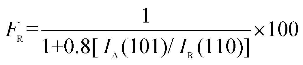
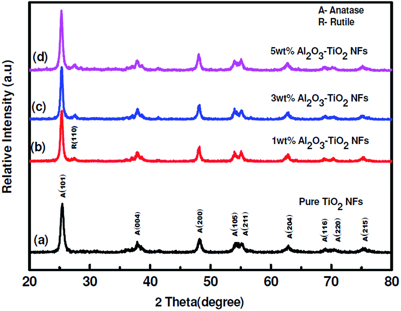
Fig. 2(a–d) represents the X-ray diffraction (XRD) patterns of pure TiO2 NFs and Al2O3 NPs embedded TiO2 NFs. Fig. 2(a) shows that the TiO2 NFs calcinations at 500 °C has a single anatase phase. The diffraction peaks representing the crystal planes (101), (004), (200), (105), (116) and (215) corresponding to the anatase phase, matches and is confirmed by the JCPDS data (Card nos 89-4920 and 89-4921). A small rutile phase along with the anatase phase has a synergistic effect on the efficient electron transport from rutile to anatase than a single anatase phase.19–21 An increase in wt% of Al2O3 NPs embedded in TiO2 NFs increased the percentage of rutile phase in TiO2 NFs, which is shown in Fig. 2(b–d). But, no peaks corresponding to Al2O3 NPs were observed. The percentage of anatase/rutile was calculated from the X-ray diffractogram using the Spurr equation:
where, IA is the intensity of (101) peak and IR is the intensity of (110) peak. The effect of different wt% of Al2O3 NPs embedded TiO2 NFs on the formation of anatase and rutile phases is presented in Table 1. The formation of rutile phase is because of geometrical effects and hence the overall number of potential surface nucleation sites per unit volume increased with a decrease in grain size which increase the rate of phase transformation.
 |
| | Fig. 2 XRD patterns of TiO2 Nanofibers and Al2O3 NPs embedded TiO2 NFs. | |
Table 1 Effect of different wt% of Al2O3 NPs embedded TiO2 NFs on the formation of anatase and rutile phases and their absorption band gap
| Weight% of Al2O3 NPs in TiO2 NF's |
% of anatase phase |
% of rutile phase |
Absorption band gap (eV) |
| 0 |
100.0 |
0.0 |
3.20 |
| 1 |
91.6 |
8.4 |
3.14 |
| 3 |
84.6 |
15.7 |
3.06 |
| 5 |
82.8 |
17.2 |
3.00 |
3.2 EDX analysis
The X-ray diffraction study of Al2O3 NPs embedded TiO2 NFs reveals no peaks for crystalline Al2O3 due to its very small wt% present in the samples. Table 2 shows EDX (energy dispersive X-ray spectrometer) characterisation results. The amount of Al2O3 NPs embedded TiO2 NFs and their corresponding EDX spectra are shown in Fig. 3(a–d).
Table 2 EDX elemental map showing distribution of Ti, Al, and O, atoms in different wt% of Al2O3 NPs embedded TiO2 NFs
| Composition of NFs |
Titanium wt(%) |
Aluminum wt(%) |
Oxygen wt(%) |
| Pure TiO2 NFs |
23.01 |
0.00 |
76.99 |
| 1 wt% Al2O3 in TiO2 NFs |
64.76 |
0.59 |
34.65 |
| 3 wt% Al2O3 in TiO2 NFs |
42.83 |
0.92 |
56.25 |
| 5 wt% Al2O3 in TiO2 NFs |
39.98 |
0.97 |
59.05 |
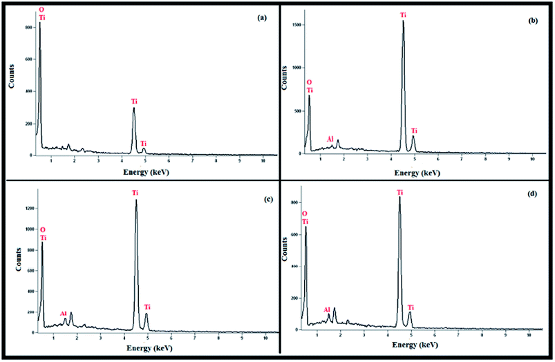 |
| | Fig. 3 EDX spectra of (a) pure TiO2 NFs (b) 1 wt% Al2O3 NPs embedded TiO2 NFs (c) 3 wt% Al2O3 NPs embedded TiO2 NFs (d) 5 wt% Al2O3 NPs embedded TiO2 NFs. | |
3.3 SEM analysis
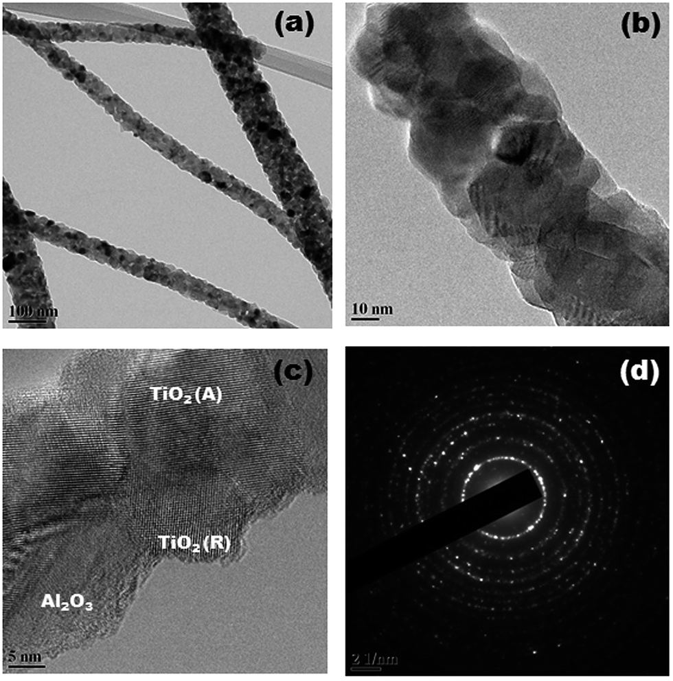
Fig. 4(a) and (b) show low resolution SEM images of as-spun TiO2 NFs and calcinated TiO2 NFs. It was seen that the diameter of the nanofibers after calcination at 500 °C showed an overall reduction of ∼64.7% in their average diameter with respect to as spun nanofibers, which was calculated as ∼235 nm and ∼83 nm for as-spun and calcinated TiO2 NFs, respectively. It was also observed that the continuous nature of TiO2 NFs after calcination remained unchanged without any loss to their continuity; however, some breakage was observed in the nanofibers. Fig. 5(a–d) shows SEM images of pure TiO2 NFs and different wt% of Al2O3 NPs embedded TiO2 NFs, which were taken to further investigate for any change in the morphology of TiO2 NFs. It was observed that no change in the morphologies occurred with the addition of Al2O3 NPs in TiO2 NFs and the diameter of TiO2 NFs also remains unchanged. The presence of Al2O3 NPs on TiO2 NFs was not observed because of the low contrast. Hence, further analysis was carried out using high resolution transmission electron microscopy (HRTEM). Fig. 6(a) shows a representative TEM image of 3 wt% of Al2O3 NPs embedded TiO2 NFs. It can be observed that the 3 wt% of Al2O3 NPs embedded over TiO2 NFs as-depicted by black dots. The TEM image of the interface between TiO2 and Al2O3 NPs is displayed in Fig. 6(b). The presence of the anatase TiO2, rutile TiO2 phase, and Al2O3 NPs, can be observed clearly in Fig. 6(c). In Fig. 6(d), the selected-area electron-diffraction (SAED) pattern confirms that the TiO2 Nanofibers are composed of a polycrystalline phase; i.e., the Debye–Scherrer concentric rings of (101), (004), (200), (105), (204), (220), and (215) planes. The SAED pattern is in good agreement with the XRD results. Similarly, 1 wt% and 5 wt% of Al2O3 NPs embedded TiO2 NFs show the same microstructures with no appreciable differences.
 |
| | Fig. 4 SEM images of (a) as-spun TiO2 NFs and (b) calcinated TiO2 NFs. | |
 |
| | Fig. 5 SEM images of different wt% of Al2O3 NPs embedded TiO2 NFs (a) 0 wt% (b) 1 wt% (c) 3 wt% and (d) 5 wt% after calcination at 500 °C. | |
 |
| | Fig. 6 TEM images of the 3 wt% of Al2O3 NPs embedded TiO2 NFs: (a) bright field image, (b) & (c) high resolution images at different magnifications, and (d) SAED pattern. | |
3.4 UV-vis spectral studies
The influence of different weight percentage of Al2O3 NPs embedded TiO2 NFs on dye adsorption was carried out. TiO2 NF paste was prepared using the following method; TiO2 NFs with PVP were stirred in the presence of ethanol and acetylacetone for 15 minutes, and acetic acid was added, subsequently. Finally, Triton X-100 was added as dispensing agent, followed by ethanol, and then the solution was concentrated by heating to obtain a viscous paste. These pastes were applied onto glass substrates by the doctor blade technique using adhesive tape as a frame and spacer. For each Al2O3 NPs embedded TiO2 film, two identical photoanodes were fabricating and kept in air for 1 h and then placed inside a muffle furnace (Technico India) at 450 °C for 30 minutes. After sintering, the glass substrates with different wt% of Al2O3 NPs embedded TiO2 NFs based films, were placed in a dye bath containing 0.3 mM cis-bis(isothiocyanato)bis-(2,2′bypiridyl-4,4′ dicarboxylato)ruthenium(II)bistetrabutylammonium (N719) dye in ethanol for 24 h, maintaining the sensitisation time the same for all the films such that we could avoid differences on the basis of time of sensitisation. The excess dye was removed by rinsing the surface of each glass substrates with ethanol. UV-vis spectral studies were done in solid mode for the dye adsorbed on different wt% of Al2O3 NPs embedded TiO2 NFs (Fig. 7). The increase in light absorbance by Al2O3 NPs was explained on the basis of increase in dye adsorption. The amount of dye adsorbed on the TiO2 NFs significantly increased with the addition of Al2O3 NPs from 0 wt%. to 3 wt%. The adsorption enhancement was related to an increase in Al2O3 NPs in TiO2 NFs, which made the surface of TiO2 NFs to become more basic in nature in view of high isoelectric point of Al2O3 nanoparticles (∼9.2). This helped to form strong chemisorption bonds with dye molecules via the carboxylic ends of the N719 dye.22 This improved the solar cell performances.21–24 But, in the addition to the 5 wt% of Al2O3 NPs, the adsorption of dye on TiO2 NFs decreased. This might be due to increase in the amorphous nature on the surface of TiO2 NFs, which reduced the overall surface area by blocking the porosity on the surface of the nanofibers, thereby reducing the dye adsorption.19,25 To know about the effect on the absorption band gap with increase in wt% of Al2O3 NPs embedded in TiO2 NFs, we measured the absorption band gap from the UV-vis spectra using Origin Pro-9 and their values are given in Table 1. It can be observed that there was a reduction in band gap from 3.20 eV to 3.00 eV when increasing the wt% of Al2O3 NPs from 1 wt% to 5 wt% in TiO2 NFs. The reduction in band gap is due to the addition of less valence cation (Al3+) than that of TiO2 (Ti4+), which increased the concentration of oxygen vacancies, such that the charge balance was obtained. This change introduced a defect in the system that reduced the overall grain size, which lead to a contraction in the system, thereby reducing the bandgap.
 |
| | Fig. 7 UV-vis spectra of different wt% of Al2O3 NPs embedded TiO2 NFs on adsorption of N719 dye. | |
Table 3 EIS parameters of Rs, Rct1 and Rct2 values for DSSCs fabricated using pure TiO2 NFs and Al2O3 NPs embedded TiO2 NFs
| Photoanode |
Rs |
Rct1 (Ω cm−2) |
Rct2 (Ω cm−2) |
| Pure TiO2 NFs |
15.06 |
6.89 |
23.84 |
| 1 wt% Al2O3–TiO2 NFs |
14.85 |
7.20 |
21.54 |
| 3 wt% Al2O3–TiO2 NFs |
14.70 |
6.17 |
18.42 |
| 5 wt% Al2O3–TiO2 NFs |
14.00 |
7.10 |
20.50 |
3.5 Electrochemical impedance studies
The electrochemical impedance study was carried out to study the effect of different wt% of Al2O3 NPs embedded TiO2 NFs on charge transfer resistance. Nyquist plot consisted of two semicircles (Fig. 8 and Table 3), corresponding to the charge transport resistance at counter electrode/electrolyte (Rct1) in higher frequencies (kilohertz range) and at electrical contacts between FTO/TiO2 NFs or among TiO2 NFs. The larger semicircle at lower frequencies corresponded to charge transfer resistance at TiO2 NFs/dye/electrolyte interface (Rct2) and the Warburg diffusion process of I−/I3− redox couple in electrolyte (Zw) at open circuit voltage under darkness.26–28 Though Rct2 virtually overlapped Zw, the identical semicircles at higher frequency suggested that Al2O3 NPs embedded in TiO2 NFs did not affect the charge transfer at counter electrode/electrolyte interface. Rct2 value decreased with the increase in Al2O3 NPs embedded in TiO2 NFs up to 3 wt% and then increased with further increase in Al2O3 NPs embedded in TiO2 NFs. The variations in Rct2 value were consistent with the Jsc value of respective cell, i.e., when the Rct2 value decreased, the Jsc value increased and vice versa. Increase in the Al2O3 NPs embedded in TiO2 NFs from 3 wt% to at 5 wt%, led to increase in Voc on expense of the Jsc value. This is due to the reduction in dye adsorption and less electrolyte uptake, which led to decrease in overall device power conversion efficiency (PCE).
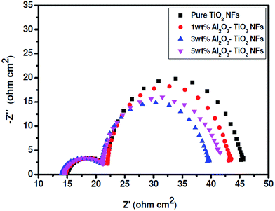 |
| | Fig. 8 Nyquist Plots of DSSCs fabricated with different wt% of Al2O3 NPs embedded TiO2 NFs. | |
3.6 Photovoltaic measurements
Table 4 summarizes the photovoltaic parameters of DSSCs based on different wt% of Al2O3 NPs embedded TiO2 NFs. Fig. 9 represents the current density–voltage (J–V) characteristics of DSSCs fabricated with various wt% Al2O3 NPs embedded TiO2 NFs as photoanodes. The DSSC fabricated using 3 wt% Al2O3 NPs embedded TiO2 NFs as photoanode exhibited an improved power conversion efficiency of 36.2% with respect to DSSC fabricated using pure TiO2 NFs. The obtained results were compared with the results reported for Al2O3 coated TiO2 nanoparticles based DSSCs (Table 5). The Al2O3 NPs embedded TiO2 NFs based DSSC exhibited higher percentage in PCE than other similar systems reported in the literature.23,29,30 The higher efficiency of the cell is due to reduction in the back carrier recombination by the addition of Al2O3 NPs, which have higher conduction band edge and higher band gap (7 eV) than pure TiO2 NFs (3.2 eV) allowing only a minor carrier flow to the oxidised dye molecules or in other words to the oxidised redox couple leading to an increase in conduction band electrons as reflected by increase in Jsc. In the case of 5 wt% of Al2O3 NPs embedded TiO2 NFs, excess of Al2O3 decreased the dye adsorption and electrolyte uptake and increased the % of rutile phase, thereby decreasing the PCE.
 |
| | Fig. 9 Photocurrent density–voltage characteristics of DSSCs fabricated with different wt% of Al2O3 NPs embedded TiO2 NFs. | |
Table 4 Photovoltaic parameters of DSSCs fabricated with different wt% of Al2O3 NPs embedded TiO2 nanofibers
| Photoanode |
Jsc (mA cm−2) |
Voc (V) |
FF |
η (%) |
| Pure TiO2 NFs |
10.3 |
0.64 |
73 |
4.81 |
| 1% Al2O3–TiO2 NFs |
10.8 |
0.66 |
75 |
5.35 |
| 3% Al2O3–TiO2 NFs |
11.7 |
0.70 |
80 |
6.55 |
| 5% Al2O3–TiO2 NFs |
11.0 |
0.72 |
76 |
5.85 |
Table 5 Comparison of photovoltaic performances of DSSCs fabricated by using Al2O3 coated TiO2 as photoanodes
| Photoanode |
Voc (mV) |
Jsc (%) |
FF (%) |
Cell efficiency (%) |
% of improvement in PCE (%) |
Ref. |
| TiO2/Al2O3 core shell |
705.6 |
19.0 |
63 |
8.40 |
35.5 |
23 |
| Al2O3 coated nanoporous TiO2 films |
750 |
10.9 |
65 |
5.00 |
30.0 |
29 |
| Al2O3 coated nanoporous TiO2 |
470 |
9.5 |
52 |
2.60 |
33.5 |
30 |
| Al2O3 NPs embedded TiO2 NFs |
750 |
11.7 |
80 |
6.55 |
36.2 |
Present work |
4. Conclusions
DSSC fabricated using 3 wt% of Al2O3 NPs embedded TiO2 NFs exhibited an overall percentage of improvement in PCE of 36.2% compared to standard DSSC made from pure TiO2 NFs as photoanode. This improvement is due to the presence of an optimum rutile phase (15.7%) which helped in the synergetic effect to easily improve the electron transport from rutile to anatase phase. This improved the dye adsorption which in turn improved the photovoltaic performance of the cell by increasing both the Voc and Jsc up to 3 wt% of Al2O3 NPs embedded in TiO2 NFs. But in 5 wt% of Al2O3 NPs embedded in TiO2 NFs, the dye adsorption lowered and offered high resistance to flow of electrons across TiO2 NFs| Al2O3 |dye| electrolyte interface. An increase in Jsc of the cell was in agreement with the decrease in resistance up to 3 wt% of Al2O3 NPs embedded in TiO2 NFs. With further increase of Al2O3 NPs embedded in TiO2 NFs, the resistance to the flow of electrons across the TiO2 NFs/dye/electrolyte (Rct2) increased. Because of the increase in the tunnelling length by the large number of Al2O3 NPs on the surface of TiO2 that hindered the electron injection, this leads to a decrease in Jsc and also the efficiency of the cell. Thus 3 wt% of Al2O3 NPs embedded TiO2 NFs with 15.7% rutile phase could be used as an effective photoanode for DSSC to improve the efficiency of the cell.
Acknowledgements
The authors gratefully acknowledge the CSIR ref. no. 01(2359)/10/EMR-II, New Delhi for the financial support.
References
- B. O. Regan and M. Gratzel, Nature, 1991, 353, 737–740 CrossRef.
- M. Gratzel, Nature, 2001, 414, 338–344 CrossRef CAS PubMed.
- A. Hagfeldt and M. Gratzel, Acc. Chem. Res., 2000, 33, 269–277 CrossRef CAS PubMed.
- Y. G. Guo, Y. S. Hu, W. Sigle and J. Maier, Adv. Mater., 2007, 19, 2087–2091 CrossRef CAS.
- S. A. Akbar, L. B. Younkman and P. K. Dutta, ACS Symp. Ser., 1998, 690, 161–167 CrossRef CAS PubMed.
- M. K. Nazeeruddin, F. De Angelis, S. Fantacci, A. Selloni, G. Viscardi, P. Liska, S. Ito, B. Takeru and M. G. Gratzel, J. Am. Chem. Soc., 2005, 127, 16835–16847 CrossRef CAS PubMed.
- A. Fujishima and K. Honda, Nature, 1972, 238, 37–38 CrossRef CAS.
- A. C. Fisher, L. M. Peter, E. A. Ponomarev, A. B. Walker and K. G. U. Wijayantha, J. Phys. Chem. B, 2000, 104, 949–958 CrossRef CAS.
- J. Bisquert and V. S. Vikhrenko, J. Phys. Chem. B, 2004, 108, 2313–2322 CrossRef CAS.
- K. Onozuka, B. Ding, Y. Tsuge, T. Naka, M. Yamazaki, S. Sugi, S. Ohno, M. Yoshikawa and S. Shiratori, Nanotechnology, 2006, 17, 1026–1031 CrossRef CAS PubMed.
- M. Y. Song, Y. R. Ahn, S. M. Jo, D. Y. Kim and J.-P. Ahn, Appl. Phys. Lett., 2005, 87, 113113 CrossRef PubMed.
- E. Palomares, J. N. Clifford, S. A. Haque, T. Lutz and J. R. Durrant, J. Am. Chem. Soc., 2003, 125, 475–482 CrossRef CAS PubMed.
- A. Kay and M. Gratzel, Chem. Mater., 2002, 14, 2930–2935 CrossRef CAS.
- Z.-S. Wang, C.-H. Huang, Y.-Y. Huang, Y.-J. Hou, P.-H. Xie, B.-W. Zhang and H.-M. Cheng, Chem. Mater., 2001, 13, 678–682 CrossRef CAS.
- S. G. Chen, S. Chappel, Y. Diamant and A. Zaban, Chem. Mater., 2001, 13, 4629–4634 CrossRef CAS.
- H. Alarcon, G. Boschloo, P. Mendoza, J. L. Solis and A. Hagfeldt, J. Phys. Chem. B, 2005, 109, 18483–18490 CrossRef CAS PubMed.
- S. N. Karthick, K. V. Hemalatha, C. Justin Raj, A. Subramania and H.-J. Kim, Thin Solid Films, 2012, 520, 7018–7021 CrossRef CAS PubMed.
- A. Subramania, E. Vijayakumar, N. Sivasankar, A. R. Sathiya Priya and K.-J. Kim, Ionics, 2013, 19, 1649–1653 CrossRef CAS.
- T. K. Yun, S. S. Park, D. Kim, J.-H. Shim, J. Y. Bae, S. Huhc and Y. S. Won, Dalton Trans., 2012, 41, 1284–1288 RSC.
- J. Ding, Y. Li, H. Hu, L. Bai, S. Zhang and N. Yuan, Nanoscale Res. Lett., 2013, 8, 5–9 CrossRef PubMed.
- G. H. Li, C. P. Richter, G. W. Brudvig and V. S. Batista, Dalton Trans., 2009, 45, 10078–10085 RSC.
- X. T. Zhang, I. Sutanto, T. Taguchi, K. Tokuhiro, Q. B. Meng, T. N. Rao, A. Fujishima, H. Watanabe, T. Nakamori and M. Uragami, Sol. Energy Mater. Sol. Cells, 2003, 80, 315–326 CrossRef CAS PubMed.
- V. Ganapathy, B. Karunagaran and S.-W. Rhee, J. Power Sources, 2005, 195, 5138–5143 CrossRef PubMed.
- C. P. Lee, P. Y. Chen, R. Vittal and K. C. Ho, Phys. Chem. Chem. Phys., 2010, 12, 9249–9255 RSC.
- E. Barajas-Ledesma, M. L. Garcia-Benjume, I. Espitia-Cabrera, M. Ortiz-Gutierrez, F. J. Espinoza-Beltran, J. Mostaghine and M. E. Contreras-Garcia, Mater. Sci. Eng., B, 2010, 174, 71–73 CrossRef CAS PubMed.
- L. Han, N. Koide, Y. Chiba and T. Mitate, Appl. Phys. Lett., 2004, 84, 2433–2435 CrossRef CAS PubMed.
- Z. Zhang, S. M. Zakeeruddin, B. O. Regan, R. Humphry-Baker and M. Gratzel, J. Phys. Chem. B, 2005, 109, 21818–21824 CrossRef CAS PubMed.
- R. Kern, R. Sastrawan, J. Ferber, R. Stangl and J. Luther, Electrochim. Acta, 2002, 47, 4213–4225 CrossRef CAS.
- E. Palomares, J. N. Clifford, S. A. Haque, T. Lutz and R. James, Chem. Commun., 2002, 14, 1464–1465 RSC.
- X.-T. Zhanga, I. Sutantoa, T. Taguchia, K. Tokuhiroa, Q.-b. Menga, T. N. Raoa, A. Fujishimaa, H. Watanabeb, T. Nakamorib and M. Uragami, Sol. Energy Mater. Sol. Cells, 2003, 80, 315–326 CrossRef PubMed.
|
| This journal is © The Royal Society of Chemistry 2014 |
Click here to see how this site uses Cookies. View our privacy policy here.