
Water assisted crystallization, gas sensing and photo-electrochemical properties of electrochemically synthesized TiO2 nanotube arrays†
B. Manmadha Rao and
Somnath C. Roy*
Environmental Nanotechnology Laboratory, Department of Physics, Indian Institute of Technology Madras, Chennai 600036, India. E-mail: somnath@iitm.ac.in
First published on 23rd September 2014
Abstract
We report a simple water assisted crystallization process for electrochemically synthesized TiO2 nanotube (TNT) arrays at room temperature (30 °C) and near-room temperature (50 °C). The TNT array samples kept immersed in de-ionized water at room temperature for durations from 1 day to 6 days show a distinct anatase phase confirmed by both X-ray diffraction and transmission electron microscopy. When the process is repeated at an elevated temperature of 50 °C, the crystallization is accelerated with the appearance of an anatase phase within 8 h of treatment. Interestingly, addition of 0.05 M HCl or HNO3 to the DI water during treatment helped in forming the rutile phase of TiO2, along with the dominant anatase phase. By carefully choosing the nanotube parameters (length and diameter) it has been possible to retain the nano-tubular morphology, which is advantageous for applications such as solar cells and gas sensing. Finally, we show the gas sensing and photo-electrochemical characteristics of the DI water crystallized TNT arrays. The samples show good sensitivity and appreciable values of photo-current under the given experimental conditions.
Introduction
Achieving crystallization of materials at lower temperatures has always been a prime objective for materials scientists because it not only allows a lower thermal budget but also makes it possible to develop technologies involving materials that cannot withstand higher processing temperatures. For example, in the fabrication of solar cells on flexible polymer substrates, the processing temperature of the active, light absorbing layer is very much limited by the temperature capabilities of the polymer substrate and hence, lowering the crystallization temperature of the active layer may lead to a successful device technology. Metal-oxides, such as TiO2, is preferred in many applications such as in solar cells,1,2 photo-catalysis,3–5 biocompatible materials,6–8 sensors,9 etc., because of superior photo-response, charge carrier mobility, chemical and thermal stability, ease of synthesis and non-toxicity. In particular, the aligned nano-structures such as TiO2 nano-tubes (TNTs) formed by electrochemical anodization have shown potentials for various applications in the past 10 years because of higher surface to volume ratio, uni-directional charge transport, and the availability of both inner and outer surfaces.10 The electrochemical anodization technique, however, results in amorphous TNTs on Ti foil substrates and hence, a high temperature thermal treatment in a conventional furnace is usually employed to achieve crystallinity. Recently, we have shown that the crystallization can also be achieved at a substantially lower temperature of 200 °C by employing a simple solvothermal technique in which, the amorphous TNTs are subjected to an alcohol treatment in a pressurized container and the samples treated with iso-butanol show crystallinity comparable to that of furnace annealed samples.11 The solvothermal treatment, however, being a high-pressure technique, results in rougher surfaces and may also lead to damages to the TNT arrays. In order to avoid such possibility, crystallization at or near room temperature is desired which may not lead to any thermal stress either in the substrate or the active material.Water assisted crystallization of TiO2 at temperatures below 200 °C has recently been reported in the literature in which, water molecules are assumed to bond with amorphous TiO2 and help in forming anatase phase after a subsequent dehydration process. Liao et al.12 reported crystallization of amorphous TNTs in hot water at 90 °C. The samples treated for 35 h showed photocatalytic activity comparable to commercial P25 powder. However the use of TNTs in the powder form for photo-catalysis experiments demonstrated poor adhesion of the crystallized materials with the underlying substrate. Wang et al.13 showed spontaneous crystallization of the TNTs in water at room temperature, transforming as anodized amorphous material into anatase phase. However, the nanotube structure could not be retained and the resulting material with best crystallization transformed into nanowire morphology. Recently, Su et al.14 also demonstrated room temperature spontaneous crystallization of titania powder into anatase phase. However, in the absence of any solvent/additives, it took about 80–90 days to achieve crystallinity that resulted in better efficiency for hydrogen generation compared to the benchmark P25 material. Other efforts to achieve near-room temperature crystallization of the TNTs such as ‘in situ’ crystallization during anodization process have also been reported. Sorachon Yoriya and co-workers obtained discrete and partially crystalline free standing TNTs by using diethylene glycol as basic electrolyte. Even though this process achieved partial crystallization, it has the disadvantage of very slow growth rate.15 In a similar strategy, Nageh and co-workers obtained crystalline TiO2 nanotube arrays up to 1.2 μm in length. However, this process also suffered from slower growth rate and resulting shorter nanotubes. Moreover, pre-anodization soaking of titanium foil in an oxidizing agent was required which involved thermal treatment (H2O2, 80 °C; (NH4)2S2O8, 120 °C).16
In the present work, we report crystallization of longer (18 μm) nanotubes at and near room temperature (30 °C and 50 °C) by immersing the samples in DI water. A systematic approach has been taken by studying crystallization as a function of water treatment time and optimum conditions for crystallization has been obtained. The resulting TNT arrays are found to posses good adhesion with the underlying Ti substrate and the nanotube morphology was successfully preserved. Best crystallinity at room temperature was obtained in about 96 h and the process carried out at 50 °C led to comparable crystallinity in around 8 h. The effect of adding HCl or HNO3 in the water was also studied and the resulting phase evolution has been discussed. Furthermore, we have explored the application of water-crystallized TNTs for the sensing of methane gas and also in the photo-electro-chemical hydrogen generation and the results have been presented.
Experimental
Syntheses of TiO2 nanotubes
Titanium foils (0.25 mm thickness, 99.7% pure, Sigma-Aldrich) were ultrasonically cleaned in de-ionized water (DIW), acetone and isopropyl alcohol each for 10 min. Two electrodes with titanium foil (Ti) as anode and platinum foil (Pt) as cathode were dipped in electrolyte solution comprising of 4 vol% of DIW and 0.2 wt% of NH4F in ethylene glycol. The anodization was performed for duration of 2 h at a constant voltage of 60 V. After the anodization, the resulting TNT array film was ultrasonically cleaned in isopropyl alcohol around 15 to 20 seconds to remove debris.DI water treatment of TNT
The samples were treated in DIW at room temperature by placing as anodized TNT in 100 ml beaker. The sealed beaker was kept in dark room for 1, 2, 4 and 6 days respectively. Here all the samples were placed vertically inside the beaker. After completion of this process at desired times, the samples were cleaned thoroughly in DIW around 30 seconds and dried in normal atmosphere. In room temperature crystallization process (30 °C), the degree of crystallization is depends only on time (number of days). In all cases, the sample (TNTs) size was 2 cm × 2 cm. This process was repeated by keeping the DIW filled beaker at 50 °C and also for a solution of 0.05 M HCl.Characterization
The X-ray diffraction (XRD) analysis was performed using a PANalytical X-pert PRO system in glancing angle (2°) geometry with a scan rate of 0.02° s−1. The field-emission scanning electron microscopy (FESEM) was done with the help of FEI Quata 400 system. High-resolution transmission electron microscopy (HRTEM) was performed with a FEI Tecnai-20-FEG-S-twin system operating at 200 kV. The gas sensing experiments were performed using an indigenously designed gas sensing set-up, in which, the gas flow was controlled through MKS mass flow controllers and the resistance changes were recorded through an Agilent 4339B High Resistance meter. All instruments were interfaced to a computer using LabView software. Photocurrent measurements were performed with a CH instruments model 660C electrochemical analyser using 1 M NaOH as the electrolyte. The TNT sample and Pt foil was used as the photo-anode and the counter-electrode respectively. A Lumen Dynamics S2000 Omnicure lamp was used to provide UV-visible illumination in the range of 320 to 500 nm and the power of 100 mW cm−2 was used for the experiments.Result and discussion
Fig. 1a shows glancing angle XRD pattern of TNT arrays after DI water treatment at room temperature (30 °C) for different time durations (1 day to 6 days). All water treated samples show peaks corresponding to TiO2 anatase phase (JCPDS file no. 894203); however, the intensity of the peaks gradually increases with the duration of treatment from 1 day to four days, beyond which saturation is observed. When the DI water treatment is repeated at 50 °C, the formation of the anatase phase is accelerated and samples with similar degree of crystallinity are obtained within 8 h (as compared to 4–6 days for DI water treatment at room temperature). The XRD patterns corresponding to this series of samples (treated at 50 °C) are presented in Fig. 1b. In this case too, the degree of crystallization increases with duration of DI water treatment from 2 h to 8 h, beyond which there is no significant enhancement. In order to investigate the effect of HCl in the crystallization of TNT samples, some of the samples were treated in DI water mixed with 0.05 M HCl. The XRD patterns of the resulting samples (treated at room temp.) are shown in Fig. 1c. In this case, no crystallization is observed after 1 day of treatment; however, peaks corresponding to both anatase and rutile phase of TiO2 appear in the samples treated in DI water for the durations of 2–6 days. Although the anatase phase still remains the dominant one, the appearance of rutile phase appears to be driven by the addition of HCl or HNO3 to DI water, which will be discussed in the subsequent sections. | ||
| Fig. 1 (a) XRD of room temperature crystallization processed TNT in DIW at 1, 2, 4 and 6 days. (b) XRD of 50 °C temperature crystallization processed TNT in DIW at 2, 4, 8 and 12 h. (c) XRD of room temperature crystallization processed TNT in 0.05 M HCl at 1, 2, 4 and 6 days. (d) XRD of room temperature crystallization processed TNT in 0.05 M HCl and 0.05 M of HNO3 at 6 days. | ||
The FESEM images of as-anodized and DI water treated samples are shown in Fig. 2. Both the top view and cross-sectional images for each sample are presented. The top view image of the as-anodized sample (Fig. 2a) shows the TNT array with about 120 nm diameter for the individual tubes and the corresponding cross-sectional image (Fig. 2b) reveals that the length of the tubes to be around 18 μm. Fig. 2c–f shows the morphology of the TNT arrays after DI water treatment at room temperature (for 4 days) and at 50 °C (for 8 h) respectively. We find that the nanotube morphology is retained with open pores and compact nature of the TNT arrays. However, particulate formation is observed near the pores of TNTs after water treatment. Fig. 2g and h shows the morphology of the TNT arrays treated with 0.05 M HCl solution. In the case of HCl treated samples, however, the adhesion of the TNT array film to the underlying Ti metal substrate as well as the integrity (compactness) of the entire TNT arrays film is found to be much weaker compared to that of the samples treated only with DI water.
 | ||
| Fig. 2 FE-SEM images of (a and b) as anodized TNT, (c and d) water processed TNT at room temperature for 4 days (e and f) water processed TNT at 50 °C for 8 h and (g and h) 0.05 M HCl processed TNT at room temperature, 4 days. | ||
To confirm the crystallinity samples, HRTEM analysis was performed on both as-anodized and water treated samples and the results are shown in Fig. 3. The as-anodized sample shows tubular structure (Fig. 3a) with diffused rings in the selected area electron diffraction (SAED) pattern shown as inset. The HRTEM image (Fig. 3b) of the corresponding sample does not any fringes, confirming lack of crystallinity in the sample. The sample treated in DI water at room temperature for 4 days retain nanotube morphology and shows spotted rings in the SAED pattern (Fig. 3c and inset) indicating crystalline nature. The high resolution image in Fig. 3b reveals lattice fringes and the measured d-spacing of 3.5 Å corresponds to the dominant (101) planes of the anatase phase.
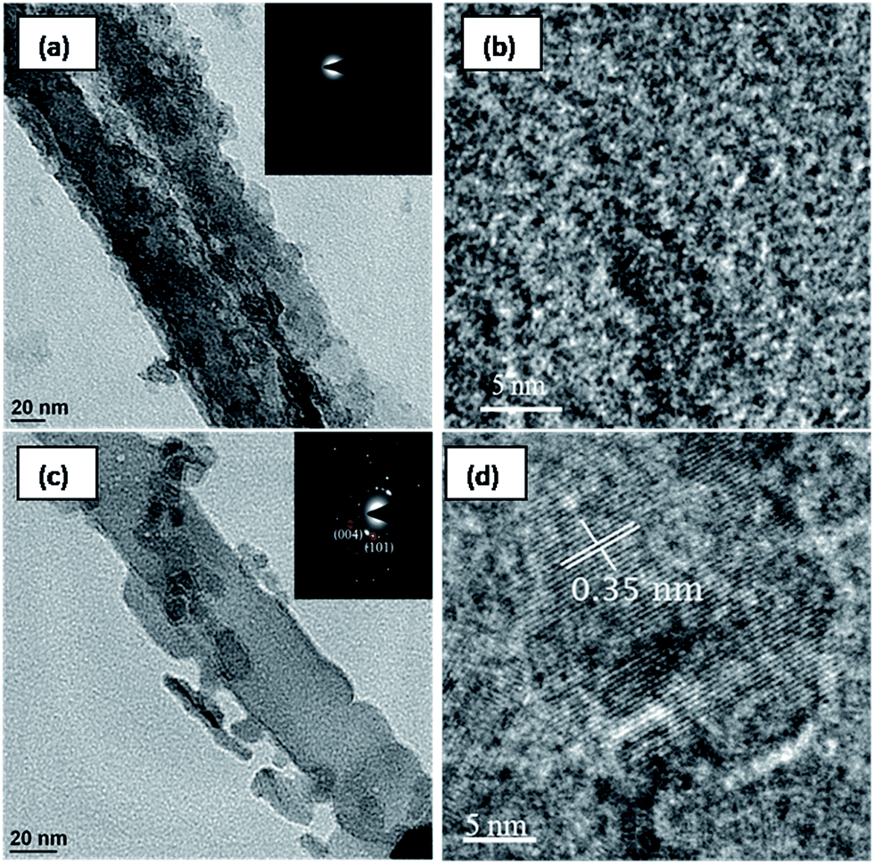 | ||
| Fig. 3 HRTEM images of (a and b) as anodized TNT and (c and d) DIW processes TNT at room temperature for 4 days. | ||
It is well known that TiO6 octahedra are the building block of all three phases of TiO2 (anatase, rutile and brookite). As anodized TNTs in amorphous form have surface hydroxyl groups attached to the TiO6 octahedras. In the presence of water under DIW treatment, the lone pair of electrons from oxygen in water form bridge bonding with the TiO6 octahedra through the surface hydroxyl groups. This bridge bonding through the water molecules brings the two or more octahedra together linking them by a triangular face. A subsequent dehydration process leaves the two Ti ions linked by two oxygen ion vertexes, and thus sharing a face. In this way, more octahedra join by sharing a face which leads to the formation of the anatase structure.13,17 This is explained schematically in Fig. 4a.
 | ||
| Fig. 4 (a) Schematic diagram of anatase phase of TiO2 formation mechanism. (b) Schematic diagram of rutile phase of TiO2 formation mechanism. | ||
In the presence of HCl or HNO3, however, we observe existence of rutile phase in addition to the dominant anatase phase. To understand the possible mechanism of rutile phase formation, we recall that in the anatase phase TiO6 octahedras are joined together by sharing 4 edges and whereas in rutile phase TiO6 octahedras are joined together by sharing 2 edges. In conventional thermal crystallization process rutile phase appears between 500–700 °C due to the creation of oxygen vacancies. These TiO6 octahedra with oxygen vacancies become unstable and the stability is achieved by rearrangement in the rutile phase. In the case of DIW assisted crystallization in presence of HCl or HNO3, Cl− or NO3− ions tends to distort the arrangement of the TiO6 octahedra, which results in the rearrangement of the TiO6 octahedra leading to the formation of the rutile phase.19 In addition, the effect of hydroxyl groups that helps in the bridge bonding towards anatase formation is also reduced because of the presence of H+ ions. The protonation of the surface of the amorphous TiO2 hinders the formation of kinetically favoured anatase phase.17–19 The relative proportion of the rutile phase can be increased further by adding HCl or HNO3 to DI water; however, the TNT array film became unstable having decreased adhesion to the substrate with increase in the HCl or HNO3 concentration. The increased concentration of acid promotes chemical dissolution (etching) of the material. Since the TiO2 nanotube arrays form only a thin layer over the underlying Ti metal foil, the initiation of the chemical etching is followed by the tendency of the entire oxide layer to be peeled off from the substrate, leading to decreased adhesion. This is explained schematically in Fig. 4b.
In contrast to the results obtained by Wang et al.,13 we did not observe nanotube to nanowires conversion. The tubular structure was preserved with well-defined pore openings along with highly aligned morphology. This can be attributed to the higher diameter of the as prepared TNTs (120 nm) compared to that used by Wang's group (60 nm), which prevented the collapse of the inner walls during the water treatment process. Though, it has been shown through BET analysis that, the nanowire morphology had resulted in a higher surface area compared to that of the nanotubes, we would like to emphasize on the fact that a compact layer of aligned nanorods/nanowires arrays without any spacing between the individual rods/wires practically offers only a two-dimensional surface as compared to nanotube morphology which, due to the presence of the open pores down the length of the entire tubes, behaves like a quasi-3d structure. Consequently, for applications such as gas sensing and dye-sensitized solar cells, nanotubes arrays are expected to be more effective compared to nanowire arrays.
The gas sensing properties of DIW crystallized TNT samples are tested using high purity methane (CH4) at 200 °C. The results are presented in Fig. 5a–d. The change in resistance of the samples crystallized at room temperature towards 5000 ppm of methane (Fig. 5a) is found to be highly reproducible (3 cycles shown). The gas response of the sample to different concentrations of methane is presented in Fig. 5b, wherein a proportional increase in the sensitivity with concentration is observed. Fig. 5c and d show the change in resistance of the samples crystallized at 50 °C. In this case too, we observe reproducibility and good sensing behavior. The variation of sensitivity for 5000 ppm of methane at different temperatures (of measurement) is presented in Fig. 6a. The sensitivity of samples crystallized at 50 °C is found to be higher than that of the sample crystallized at room temperature. Also, the sensitivity for the 50 °C crystallized sample shows a rapid increase at an operating (measurement) temperature of 100 °C and beyond. This is attributed to larger diameter of nanotubes in 50 °C crystallised samples. The FESEM pictures (shown in the ESI†) of room temperature processed (Fig. S1†) and 50 °C processed (Fig. S2†) samples show that, the average pore diameter in Fig. S2† is larger than that in Fig. S1.† At elevated temperatures (100 °C and beyond), when surface conditions are favorable for gas adsorption, larger diameter favors higher adsorption of gas and hence results in a rapid increase in sensitivity. The smaller diameter of room temperature processed samples (Fig. S1†) may have resulted from longer processing time (4 days) which allows precipitation on the pore mouths leading to clogging of the pores. The variation of sensitivity with gas concentration is plotted in Fig. 6b. Higher sensitivity at all test concentrations is shown by the sample processed at 50 °C; however, the sensitivity saturates at higher ppm levels. This indicates better sensing behaviour for lower concentrations of methane.
 | ||
| Fig. 5 (a) Repetitive response of the DIW (room temperature; 4 days) treated TNT to methane (5000 ppm) at 200 °C. (b) Response of the DIW (room temperature; 4 days) treated TNT to different concentration of methane at 200 °C. (c) Repetitive response of the DIW (50 °C; 8 h) treated TNT to methane (5000 ppm) at 200 °C. (d) Response of the DIW (50 °C; 8 h) treated TNT to different concentration of methane at 200 °C. | ||
 | ||
| Fig. 6 (a) % of sensitivity variation with temperature to methane (5000 ppm). (b) % of sensitivity variation with gas concentration to methane at 200 °C. | ||
The photo-current measurements are performed at a constant voltage of 0.8 V (using Ag/AgCl reference electrode) in 1 M NaOH electrolyte and the normalized data are shown in Fig. 7. A sharp photo-response is observed with steady photo-currents of about 0.39 mA cm−2 and 0.54 mA cm−2 during light exposure from the samples crystallized at room temperature and at 50 °C respectively. This can be attributed to better crystallinity in sample processed at 50 °C. A comparative view of the XRD patterns is presented in Fig. S3, ESI,† which shows higher peak heights in 50 °C processed sample as compared to the sample processed at room temperature. This shows good potential of these samples for use in photo-electrochemical hydrogen generation.
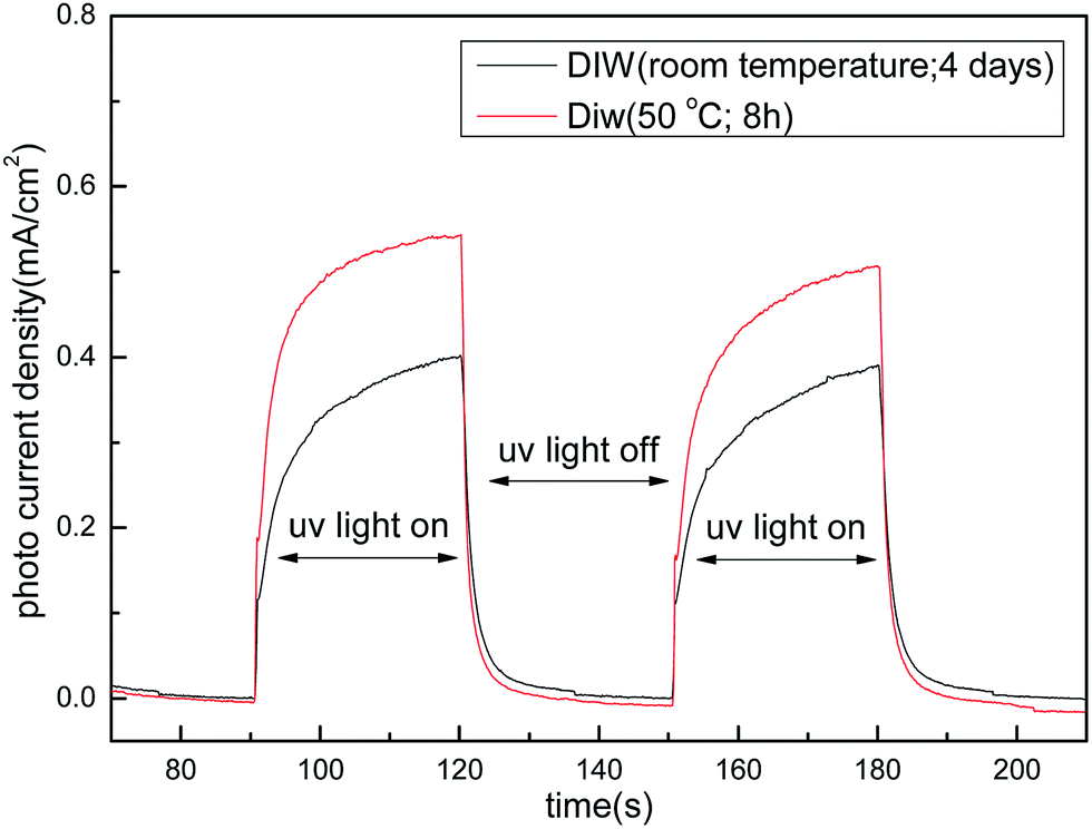 | ||
| Fig. 7 Photo current response of DIW (room temperature; 4 days) treated TNT and DIW (50 °C; 8 h) treated TNT. | ||
Conclusions
De-ionized water treatment of the amorphous TiO2 nanotube arrays results in well-crystallized TNT arrays in the anatase phase, thereby offering an energy-efficient, simple and low-cost chemical alternative to the conventional thermal annealing process. Such a crystallization takes place by the re-orientation and coupling of the TiO6 octahedra under the influence of chemical bonds between water molecules and surface hydroxyl ions attached to the amorphous TNT. A small amount of rutile phase of TiO2 can also be incorporated by adding HCl or HNO3 to DI water in a limited quantity. In contrast to a previous report wherein a structural transformation from nanotubes to nanowires was observed, the nanotubular morphology could be retained in the preset case by careful selection of tube diameter that prevents collapse of the inner tube walls during the water processing. The crystallization process is found to be accelerated by carrying out the water treatment at an elevated temperature of 50 °C. The gas sensing characteristics of the water crystallized TNT arrays are performed for different concentration of methane (CH4), which showed higher sensitivity for the sample treated at 50 °C and a proportional increase in sensitivity at lower concentrations of methane. This establishes the usefulness of such materials for methane sensing at lower concentrations. Furthermore, photo-current measurements with high-pressure Hg lamp (320–500 nm) in the presence of 1 M NaOH solution resulted in current densities of 0.54 mA cm−2 and 0.39 mA cm−2 from TNT samples treated with DI water at 50 °C and 30 °C respectively. We conclude that such water assisted crystallization of TNT arrays will be very helpful in developing cost-effective, energy-efficient device technologies, and particularly, in the fabrication of devices on flexible polymer substrates that cannot withstand high temperatures of a conventional crystallization process.Acknowledgements
Financial support from the IIT Madras (New Faculty Seed Grant), Department of Science and Technology, Govt of India (Fast Track Scheme for Young Scientists) and Nissan Research Support Programme is gratefully acknowledged. The authors also thank Mr B. Kumaran for helping in the interfacing of gas sensing system with computer and Ch. Venkatarao for helping in DC magnetron sputtering for making electrical contacts.References
- D. Kuang, J. Brillet, P. Chen, M. Takata, S. Uhida, H. Miura, K. Sumioka, S. M. Zakeeruddin and M. Gratzel, ACS Nano, 2008, 2, 1113–1116 CrossRef CAS PubMed.
- O. K. Varghese, M. Paulose and C. A. Grimes, Nat. Nanotechnol., 2009, 4, 592–597 CrossRef CAS PubMed.
- M. Altomare, K. Lee, M. S. KiyoungKillian, E. Sellil and P. Schmuki, Chem.–Eur. J., 2013, 19, 5841–5844 CrossRef CAS PubMed.
- S. C. Roy, O. K. Varghese, M. Paulose and C. A. Grimes, ACS Nano, 2010, 4, 1259–1278 CrossRef CAS PubMed.
- X. Zhang, F. Han, B. Shi, S. Farsinezhad, G. P. Dechaine and K. Shankar, Angew. Chem., 2013, 51, 12732–12735 CrossRef PubMed.
- S. C. Roy, M. Paulose and C. A. Grimes, Biomaterials, 2007, 28, 4667–4672 CrossRef CAS PubMed.
- P. Kar, A. Pandey, J. J. Greer and K. Shankar, Lab Chip, 2012, 12, 821–828 RSC.
- E. Gongadze, D. Kabaso, S. Bauer, J. Park, P. Schmuki and A. Lglic, Mini-Rev. Med. Chem., 2013, 13, 194–200 CAS.
- O. K. Varghese, D. Gong, M. Paulose, K. G. Ong, E. G. Dickey and C. A. Grimes, Adv. Mater., 2003, 15, 624–627 CrossRef CAS.
- S. Rani, S. C. Roy, M. Paulose, O. K. Varghese, G. K. Mor, S. Kim, S. Yoria, T. J. LaTempa and C. A. Grimes, Phys. Chem. Chem. Phys., 2010, 12, 2780–2800 RSC.
- B. Manmadha rao and S. C. Roy, J. Phys. Chem. C, 2014, 118, 1198–1205 Search PubMed.
- Y. Liao, W. Que, P. Zhong, J. Zhang and Y. He, ACS Appl. Mater. Interfaces, 2011, 3, 2800–2804 CAS.
- D. Wang, L. Liu, F. Zhang, K. Tao, E. Pippel and K. Domen, Nano Lett., 2011, 11, 3649–3655 CrossRef CAS PubMed.
- J. Su, X. Zou, G. Li, Y. Jiang, Y. Cao, J. Zhao and J. Chen, Chem. Commun., 2013, 49, 8217–8219 RSC.
- S. Yoriya, G. K. Mor, S. Sharma and C. A. Grimes, J. Mater. Chem., 2008, 18, 3332 RSC.
- K. A. Nageh, K. Shankar and C. A. Grimes, Adv. Mater., 2008, 20, 3942–3946 CrossRef.
- K. Yanagisawa and J. Ovenstone, J. Phys. Chem. B, 1999, 103, 7781–7787 CrossRef CAS.
- A. Mathews, Am. Mineral., 1976, 61, 419–424 Search PubMed.
- S. Dai, Y. Wu, T. Sakai, Z. Du, H. Sakai and M. Abe, Nanoscale Res. Lett., 2010, 5, 1829–1835 CrossRef CAS PubMed.
Footnote |
| † Electronic supplementary information (ESI) available. See DOI: 10.1039/c4ra06842d |
| This journal is © The Royal Society of Chemistry 2014 |