Efficient monolithic quasi-solid-state dye-sensitized solar cells based on poly(ionic liquids) and carbon counter electrodes†
Yaoguang Rong,
Zhiliang Ku,
Mi Xu,
Linfeng Liu,
Min Hu,
Ying Yang,
Jiangzhao Chen,
Anyi Mei,
Tongfa Liu and
Hongwei Han*
Michael Grätzel Center for Mesoscopic Solar Cells, Wuhan National Laboratory for Optoelectronics, School of Optical and Electronic Information, Huazhong University of Science and Technology, Wuhan, Hubei 430074, P.R. China. E-mail: hongwei.han@mail.hust.edu.cn; Fax: +86 027 877 930 27; Tel: +86 027 877 930 27
First published on 23rd January 2014
Abstract
A poly(ionic liquid) (PIL), poly(1-alkyl-3-vinylimidazolium iodide), was synthesized and employed to prepare a quasi-solid-state electrolyte for dye-sensitized solar cells. The PIL functioned as the charge transfer intermediate, the source of the redox couple and also the gelator in the electrolyte. Assembled with this electrolyte and a carbon counter electrode, a power conversion efficiency of 6.18% was obtained.
Growing attention has been concentrated on the utilization of renewable energy technologies, such as photovoltaics, to deal with the problems of increasing energy demand and global warming. Since Prof. M. Grätzel made a breakthrough in 1991, dye-sensitized solar cells (DSSCs) have been expected to be a potential candidate for the next-generation solar cells due to the advantages of high efficiency and low-cost fabricating procedures.1
In general, typical DSSCs have a sandwich structure with two transparent conducting glass substrates, between which comprises of a nanoporous TiO2 working electrode, a liquid-state electrolyte containing iodide and triiodide ions as redox couple, and a platinized counter electrode to collect electrons and catalyze the redox couple regeneration reaction.2 So far, the power conversion efficiency (PCE) of DSSCs based on this structure and liquid-state electrolyte has reached 11.9%.3 However, potential problems caused by liquid electrolytes, such as the leakage and volatilization of the liquid solvent, desorption and degradation of the dyes, and the corrosion of the platinum counter electrode have blocked the commercial application of DSSCs. Thus, quasi-solid-state and solid-state electrolytes, such as polymer gel electrolyte,4,5 organic hole-transporting materials,6,7 inorganic and p-type semiconductors8 have been proposed as alternatives to the liquid electrolytes.
Among various alternatives for liquid electrolytes, quasi-solid-state polymer gel electrolyte (PGE) appears to have high ionic conductivity and cell performance. For typical PGE, polymers or co-polymers such as poly(ethylene oxide) (PEO),9 poly(vinylidene fluoride-co-hexafluoropropylene) (PVDF-HFP)4 and poly(acrylonitrile-co-vinyl acetate) (PAN-VA)10 have been applied as the gelators. At the same time, iodine was employed to increase the conductivity of the electrolyte. However, introducing the iodine into the electrolytes decreased the stability and performance of DSSCs due to the sublimation of iodine and the incident light absorption by iodine.11,12 Ionic liquids (ILs), due to their good chemical and electrochemical stability, negligible vapour pressure and high ionic conductivity, have been investigated as potential electrolytes for application in DSSCs.13–15
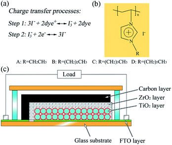
In this communication, we report a poly(ionic liquid) (PIL), poly(1-alkyl-3-vinylimidazolium iodide) (PAVII), to prepare an iodine-free quasi-solid-state electrolyte (QE). The PIL not only functions as the charge transfer intermediate and the source of redox couple in the electrolyte, but also acts as a gelling agent and provides the electrolyte system with gel character. Besides, we employ monolithic DSSCs based on mesoscopic carbon counter electrodes (CCE) to investigate the performance of this QE. Fig. 1 shows the structure of a typical monolithic DSSC. Since all the layers are fabricated by screen-printing on a single substrate for monolithic DSSCs, the thicknesses of the electrodes could be controlled precisely, and the distance between working electrode and counter electrode becomes controllable and reproducible. This makes it accessible for monolithic DSSCs to obtain reproducible photovoltaic performance.16 The chemical structure of PIL is also showed in Fig. 1 (the detail preparation procedures of the PILs and devices are given in ESI†).
 | ||
| Fig. 1 (a) Charge transfer processes in DSSCs with PAVII based electrolyte; (b) the chemical structure of PAVII and (c) the structure of a typical monolithic DSSC based on carbon counter electrode. | ||
It has been reported that imidazolium-based ionic liquid (IL) could be used as the sole charge transfer intermediate and source of redox couple in the electrolyte.13,17 The charge transfer mechanism is presented in Fig. 1. I− ions accomplish the charge transfer in the electrolyte through reacting with oxidized dye to generate I3− firstly (Step 1), and then the I3− ions return to I− species by obtaining electrons from the CCE (Step 2). Herein for the PILs, similar results were found. PAVII with different alkyl length (coded A, B, C and D as shown in Fig. 1) was dissolved in acetonitrile (0.4 M) to prepare a liquid-state electrolyte (LE). The photovoltaic parameters of the devices using PAVII based liquid-state electrolytes are summarized in Table 1. The results indicated that the synthesized PAVII worked efficiently as the source of redox couple and charge transfer intermediate in the electrolyte without any other additives. For the devices using different electrolytes, the device based on electrolyte B presented the best photovoltaic performance with the open-circuit voltage (Voc) of 588 mV, short-circuit current density (Jsc) of 12.48 mA cm−2, fill factor (FF) of 0.69 and power conversion efficiency (PCE) of 5.08%. For the PILs based electrolytes, the imidazolium cations are fixed onto the main chain of PILs, only iodide could diffuse freely. But this would not have negative effect on the conductivity of the electrolytes. Instead, it was found that the conductivity of the electrolytes increased after the polymerization of the IL monomers (Table S1†). As the length of the alkyl on the imidazolium cation increased, the conductivity of the electrolyte increased. However this enhancement did not cause obvious positive influence on the photovoltaic performance of the devices, especially for the FF and Voc. Actually, it was reported that there was a balance between the charge transport and the charge recombination when the length of the alkyl chain changed.18 In our case for the PILs based electrolytes, devices using poly(1-propane-3-vinylimidazolium iodide) (PPVII) presented the highest efficiency. Thus, we further investigated its chemical structure, thermal stability, and employed it as the polymer host to prepare the QE.
| PILs | σ/mS cm−1 | Voc/mV | Jsc/mA cm−2 | FF | PCE/% |
|---|---|---|---|---|---|
| A | 1.14 | 572 | 12.50 | 0.67 | 4.78 |
| B | 1.61 | 588 | 12.48 | 0.69 | 5.08 |
| C | 1.86 | 575 | 12.42 | 0.66 | 4.74 |
| D | 1.93 | 570 | 12.33 | 0.67 | 4.71 |
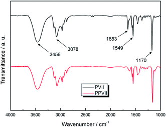
The chemical structures of the synthesized IL monomer (1-propane-3-vinylimidazolium iodide, PVII) and PIL (PPVII) were confirmed by FTIR spectra as shown in Fig. 2 and by 1H NMR (see ESI†). The adsorption peaks centred at 3456 and 3078 cm−1 are attributed to the C–H stretching vibration mode of the imidazole ring and the alkyl chains. The absorption peaks at 1170 and 1161 cm−1 are assigned to the stretching and asymmetric stretching vibrations of C–N of imidazole rings. An absorption band at around 1653 cm−1 which as ascribed to the C![[double bond, length as m-dash]](https://www.rsc.org/images/entities/char_e001.gif) C stretching band of monomer PVII disappears after polymerization while the C
C stretching band of monomer PVII disappears after polymerization while the C![[double bond, length as m-dash]](https://www.rsc.org/images/entities/char_e001.gif) N stretching vibration belonging to the imidazole ring is observed at about 1549 cm−1.19,20 According to the result of gel permeation chromatography (GPC), the polymer chain is quite uniform with a polydispersity index (PDI) of 1.026 (ESI†).
N stretching vibration belonging to the imidazole ring is observed at about 1549 cm−1.19,20 According to the result of gel permeation chromatography (GPC), the polymer chain is quite uniform with a polydispersity index (PDI) of 1.026 (ESI†).
The thermostability of PPVII was studied by thermogravimetric (TG) analysis. Fig. 3 shows the TG curve of PPVII measured in N2. The starting decomposition temperature, at which the decomposition of PPVII begins, is 263 °C. The TG result indicates that this PIL has very good thermal stability below 200 °C, making it a good candidate of electrolyte components for DSSCs.
To prepare the QE, PPVII was dissolved in acetonitrile with a weight ratio of 1![[thin space (1/6-em)]](https://www.rsc.org/images/entities/char_2009.gif) :
:![[thin space (1/6-em)]](https://www.rsc.org/images/entities/char_2009.gif) 1. The high concentration of the PIL provided the electrolyte with gel character (Fig. S2†). The devices based on QE presented much better photovoltaic performance compared with devices based on LE. Fig. 4 shows the photocurrent–voltage (J–V) curves of devices using QE and LE. Detailed photovoltaic parameters are summarized in Table 2. The Voc, Jsc and FF of the devices based on QE are 637 mV, 13.61 mA cm−2 and 0.71, respectively, finally yielding a PCE of 6.18%.
1. The high concentration of the PIL provided the electrolyte with gel character (Fig. S2†). The devices based on QE presented much better photovoltaic performance compared with devices based on LE. Fig. 4 shows the photocurrent–voltage (J–V) curves of devices using QE and LE. Detailed photovoltaic parameters are summarized in Table 2. The Voc, Jsc and FF of the devices based on QE are 637 mV, 13.61 mA cm−2 and 0.71, respectively, finally yielding a PCE of 6.18%.
| Electrolyte | Voc/mV | Jsc/mA cm−2 | FF | PCE/% | Rs/Ω | Rct1/Ω | Rct2/Ω |
|---|---|---|---|---|---|---|---|
| LE | 588 | 12.48 | 0.69 | 5.08 | 14.61 | 18.08 | 42.99 |
| QE | 637 | 13.61 | 0.71 | 6.18 | 12.26 | 12.51 | 56.95 |
Compared with devices based on LE, the Voc and Jsc both increased significantly. It was expected that these improvements had been affected by the polymer network in QE. Firstly, imidazolium cations on the polymer chain would align the anionic redox couple by electrostatic force, facilitating electron transport by the ion exchange mechanism.21 Thus, Jsc increased significantly. Secondly, for the increase of Voc, it should be related to back electron transfer reaction. Back electron transfer reaction is the reduction of I3− obtaining an electron from the conduction band of the TiO2. Suppressing back electron transfer reaction would cause increase of Voc. Here for the QE, the imidazolium cations were tethered on the main chain to form a brush-like structure.22 When the imidazolium cations were adsorbed on the surface of TiO2, a brush-like polymer network would form around the surface of TiO2. This may suppress the back electron transfer from TiO2 to the I3− and cause an increase of Voc.15 The inset of Fig. 4 shows the proposed mechanism for the polymer chain around the dye-sensitized TiO2 blocking the I3− from reacting with electron transporting in the TiO2 film.
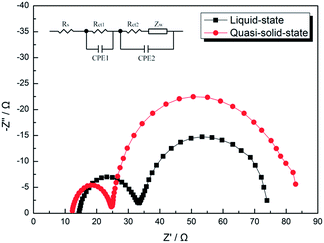
Electrochemical impedance spectroscopy (EIS) was used to quantify various resistances in the devices. The results are shown in Fig. 5. Typically, the EIS spectra of DSSCs show three semicircles in the frequency range from 50 mHz to 100 kHz. The ohmic serial resistance (Rs) corresponds to the overall series resistance. The first and second semicircles correspond to the charge-transfer resistances at the counter electrode/electrolyte (Rct1) and the TiO2/dye/carrier mediator (Rct2) respectively. The third one represents the Warburg diffusion process (Rdiff) of I−/I3− in the electrolyte.23 It is generally assumed that the second semicircle represent the recombination process between electrons in TiO2 and the electrolyte. When the diameter of the middle frequency semicircle is larger, the electron recombination at the TiO2/dye/electrolyte interface is slighter. The results indicate that the high frequency arc radius of the QE based devices is smaller than that of LE based devices, while the low frequency arc radius of the QE based devices is larger than that of the LE based devices. This means that the charge transfer resistance (Rct1) between CCE and QE is smaller than that between CCE and LE, while the recombination resistance (Rct2) at the TiO2/QE interface is larger than that at the TiO2/LE interface in the devices. The corresponding parameters obtained from the spectra are summarized in Table 2 and the fitted curves are presented in Fig. S3.† Since Rs and Rct1 of QE based devices are smaller than those of LE based devices, it could be concluded that the improvement of Jsc and FF obtained for the QE is due to the decrease of internal resistance. For Rct2, which presents the recombination reaction rate at the TiO2/electrolyte interface, QE based device is larger than LE based device, indicating the recombination reactions are effectively suppressed.
 | ||
| Fig. 5 Electrochemical impedance spectra (EIS) of the devices using LE and QE in the dark with applying a bias of the open circuit voltage. Fitted curves are presented in Fig. S3.† | ||
In summary, PPVII has been successfully synthesized and used to prepare a QE for DSSCs. The results indicated that the PPVII functioned efficiently as the charge transfer intermediate and the source of redox couple in the electrolyte. At the same time, it also acted as the polymer host in the electrolyte system providing it with gel character. Moreover, the polymer chain in the electrolyte could suppress the recombination reaction at the TiO2/electrolyte interface and result in a higher Voc. Compared with LE based devices, QE based devices presented much better photovoltaic performance and presented a PCE up to of 6.18%.
Acknowledgements
The authors acknowledge the financial support from the Ministry of Science and Technology of China (863, no. SS2013AA50303), the National Natural Science Foundation of China (Grant no. 61106056), the Fundamental Research Funds for the Central Universities (HUSTNY022), and Scientific Research Foundation for Returned Scholars, Ministry of Education of China. We also thank the Analytical and Testing Center of Huazhong University of Science and Technology (HUST) for FTIR testing.Notes and references
- B. O'Regan and M. Grätzel, Nature, 1991, 353, 737 CrossRef CAS.
- A. Hagfeldt, G. Boschloo, L. C. Sun, L. Kloo and H. Pettersson, Chem. Rev., 2010, 110, 6595 CrossRef CAS PubMed.
- M. A. Green, K. Emery, Y. Hishikawa, W. Warta and E. D. Dunlop, Prog. Photovolt: Res. Appl., 2013, 21, 827 CrossRef.
- P. Wang, S. M. Zakeeruddin, J. E. Moser, M. K. Nazeeruddin, T. Sekiguchi and M. Gratzel, Nat. Mater., 2003, 2, 402 CrossRef CAS PubMed.
- Q. J. Yu, C. L. Yu, F. Y. Guo, J. Z. Wang, S. J. Jiao, S. Y. Gao, H. T. Li and L. C. Zhao, Energy Environ. Sci., 2012, 5, 6151 CAS.
- U. Bach, D. Lupo, P. Comte, J. E. Moser, F. Weissortel, J. Salbeck, H. Spreitzer and M. Gratzel, Nature, 1998, 395, 583 CrossRef CAS PubMed.
- H. Wang, G. H. Liu, X. Li, P. Xiang, Z. L. Ku, Y. G. Rong, M. Xu, L. F. Liu, M. Hu, Y. Yang and H. W. Han, Energy Environ. Sci., 2011, 4, 2025 CAS.
- Q. B. Meng, K. Takahashi, X. T. Zhang, I. Sutanto, T. N. Rao, O. Sato, A. Fujishima, H. Watanabe, T. Nakamori and M. Uragami, Langmuir, 2003, 19, 3572 CrossRef CAS.
- J. Wu, S. Hao, Z. Lan, J. Lin, M. Huang, Y. Huang, L. Fang, S. Yin and T. Sato, Adv. Funct. Mater., 2007, 17, 2645 CrossRef CAS.
- C. Chen, H. Teng and Y. Lee, J. Mater. Chem., 2011, 21, 628 RSC.
- H. X. Wang, X. Z. Liu, Z. X. Wang, H. Li, D. M. Li, Q. B. Meng and L. Q. Chen, J. Phys. Chem. B, 2006, 110, 5970 CrossRef CAS PubMed; Z. Yu, M. Gorlov, J. Nissfolk, G. Boschloo and L. Kloo, J. Phys. Chem. C, 2010, 114, 10612 Search PubMed.
- H. Pettersson, T. Gruszecki, R. Bernhard, L. Haggman, M. Gorlov, G. Boschloo, T. Edvinsson, L. Kloo and A. Hagfeldt, Prog. Photovoltaics, 2007, 15, 113 CAS.
- G. Q. Wang, L. Wang, S. P. Zhou, S. B. Fang and Y. Lin, Chem. Commun., 2011, 47, 2700–2702 RSC.
- Y. F. Shen, Y. J. Zhang, Q. X. Zhang, L. Niu, T. Y. You and A. Ivaska, Chem. Commun., 2005, 33, 4193–4195 RSC.
- Y. F. Shen, Y. J. Zhang, X. P. Qiu, H. Q. Guo, L. Niu and A. Ivaska, Green Chem., 2007, 9, 726–753 RSC.
- Y. G. Rong and H. W. Han, J. Nanophotonics, 2013, 7, 073090–073091 CrossRef CAS PubMed.
- Y. G. Rong, X. Li, G. H. Liu, H. Wang, Z. L. Ku, M. Xu, L. F. Liu, M. Hu, Y. Yang, M. L. Zhang, T. F. Liu and H. W. Han, J. Power Sources, 2013, 235, 243 CrossRef CAS PubMed.
- W. Kubo, S. Kambe, S. Nakade, T. Kitamura, K. Hanabusa, Y. Wada and S. Yanagida, J. Phys. Chem. B, 2003, 107, 4374 CrossRef CAS.
- J. Zhao, X. Shen, F. Yan, L. Qiu, S. Lee and B. Sun, J. Mater. Chem., 2011, 21, 7326 RSC.
- X. J. Chen, J. Zhao, J. Y. Zhang, L. H. Qiu, D. Xu, H. G. Zhang, X. Y. Han, B. Q. Sun, G. H. Fu, Y. Zhang and F. Yan, J. Mater. Chem., 2012, 22, 18018 RSC.
- R. Komiya, L. Y. Han, R. Yamanaka, A. Islam and T. Mitate, J. Photochem. Photobiol., A, 2004, 164, 123 CrossRef CAS PubMed.
- M. Yoshizawa and H. Ohno, Electrochim. Acta, 2001, 46, 1723–1728 CrossRef CAS.
- L. Y. Han, N. Koide, Y. Chiba and T. Mitate, Appl. Phys. Lett., 2004, 84, 2433 CrossRef CAS PubMed.
Footnote |
| † Electronic supplementary information (ESI) available. See DOI: 10.1039/c3ra47084a |
| This journal is © The Royal Society of Chemistry 2014 |


