Role of the main adsorption modes in the interaction of the dye [COOH–TPP-Zn(II)] on a periodic TiO2 slab exposing a rutile (110) surface in a dye-sentized solar cell†
Tatiana Gomez*a,
Ximena Zarateb,
Eduardo Schottb and
Ramiro Arratia-Pereza
aDepartamento de Ciencias Químicas, Facultad de Ciencias Exactas, Universidad Andres Bello, Republica 275, Santiago, Chile
bLaboratorio de Bionanotecnología, Universidad Bernardo O'Higgins, General Gana 1780, Santiago, Chile
First published on 9th December 2013
Abstract
The high solar-to-electric-power conversion efficiency reported for 5-(4-carboxylphenyl)-10,15,20-tetrakis (2,4,6-trimethylphenyl) porphyrinatozinc(II) (TPP-Zn(II)) prompted us to study at a molecular level the interaction of this dye on the rutile surface. The –COOH group was included in the complex to anchor the dye onto the semiconductor oxide. Three main modes of molecular adsorption of the anchoring group on the oxide surface were studied, and vibrational analysis was carried out to characterize it as either a minimum energy or a transition state structure. To investigate the geometrical and electronic structures of the different modes of COOH–TPP-Zn(II) adsorption on the periodic TiO2 slab with exposed rutile (110) surfaces, we employed time-dependent density functional theory to study the optical properties of the isolated molecule TPP-Zn(II) (which was used in the DSSC), followed by periodic DFT calculations in the completed system (COOH–TPP-Zn(II) on the periodic TiO2 slab). This procedure leads to a clear identification of the most stable position of the anchoring group, that binds strongly the dye on the surface and simultaneously facilitates the electron injection. On the other hand, frontier molecular orbital spatial distributions, and the energy diagram of the electronic density of states of the dye-surface system, suggest that the dye is capable of electron injection into TiO2, as has been shown from experiments. Our computational approach is able to provide considerable insight into the electronic structure of the bond system of TPP-Zn(II)–TiO2 and to get insight into the anchoring modes, which are very important for the coupling between the dye and the semiconductor surface. This leads to an effective photocurrent energy conversion in a DSSC device.
1. Introduction
Dye sensitized solar cells (DSSCs) have attracted significant interest because they can be thought of as a low cost alternative energy resource. These devices very efficiently transform sunlight into electrical energy. Currently, the research (both experimental and theoretical) in this field constitutes an important approach towards the design of these materials, due to the possibility of solving the global demand for energy.1–6 With this concern, the scientific community has devoted a sizable effort to improve these devices, by the inclusion of novel materials such as doped metal oxides, new morphologies of semiconductors, and dyes with wider spectral light absorption ranges. DSSCs, which were introduced by O'Regan and Grätzel,1 are photovoltaic devices based on an overlayer of dye molecules adsorbed on the surface of a semiconductor such as TiO2.Typically, solar cells are composed of three basic components: a light-absorber (dye sensitizer), which harvests solar energy and generates excitons,7,8 an electron-transport agent such as a nanostructured metal oxide material (for example TiO2),9,10 and finally a hole-transport agent to support the performance of the dye and metal oxide, such as the couple I−/I3−.13–15. With regards to the second point, it is well known that the majority of the experimental studies on the interfacial ET (Electron Transfer) in dye-sensitized TiO2 systems are carried out with TiO2 particles that are a mixture of the rutile and anatase crystal forms of TiO2, with a variety of exposed surfaces, rutile (110) being one of the most stable and best-studied surfaces.11,12
The structure and stability of the dye–semiconductor interface is directly related to the efficiency of the solar energy conversion process, which starts with the harvesting of energy from the sun, followed by excited electron-injection from the dye into the conduction band of the semiconductor material. Hence, it is worth mentioning that the efficiency of the solar cells depends strongly upon the optical and electronic properties of the employed dye. In this context, efforts to find alternative efficient dyes have been currently extended, focusing in sensitizer dyes that improve the sunlight absorption in the visible and near-infrared region of the solar spectrum.16
A wide variety of dyes have been tested, and the best conversion efficiency recorded for DSSCs has been achieved using ruthenium-based dyes together with the iodide/triiodide redox couple, in Grätzel's laboratory.17 Nevertheless, ruthenium is not an earth-abundant element; therefore it is an expensive and scarce metal. Other alternatives have emerged to replace ruthenium sensitizers with dyes that can achieve the same or better efficiency while remaining inexpensive and easy to synthesize.
Nowadays, porphyrins and their related macrocycles coordinated to zinc are considered excellent alternatives as sensitizers in the design of DSSCs, because of their high efficiency in the photocurrent energy conversion reaction.18–25 These systems exhibit energy gaps around 2 eV corresponding to an excitation of around 620 nm, and so are suitable dyes for excitation by sunlight.
Bessho et al.26 highlighted the key role of donor–acceptor substituted porphyrin systems in the solar-to-electric-power conversion of DSSCs, by achieving an 11% efficiency. Importantly, this is the first time that this high efficiency has been obtained with a non-ruthenium sensitizer.
Later, Yella et al.18 reported porphyrin based DSSCs using a cobalt(II/III) redox electrolyte, which exceeded 12% efficiency. This makes TPP-Zn(II) the dye with the highest solar-to-electric power-conversion efficiency (IPCE) reported up to date.
On the other hand, Imahori and co-workers27 studied a series of monocarboxyphenyl Zn–porphyrins, with the aim of evaluating the effects of the porphyrin substituents and adsorption conditions on the photovoltaic properties of the porphyrin-sensitized TiO2 cells. Their results provide valuable information on the development of DSSCs, as they exhibit high performance when substituents such as meso-phenyl and carboxylic acid groups are attached to the meso-phenyl ring. The use of the carboxylic acid groups ensured the single anchorage of the porphyrin molecule on a TiO2 surface. In this sense, it is important to note that the dye molecule is bonded in a covalent way to the metal oxide surface, through a substituent named anchoring group. Therefore, the inclusion of an anchor can influence the strength and stability of the binding of the dye to the semiconductor, as well as the surface electron transfer rates. Besides, the anchoring of the dye leads to a long-term stability of the solar cells and also avoids aggregation. The most commonly used anchoring groups are carboxylic acid (CO2H)1,28 and phosphoric acid (PO3H2),29 among others, which have been shown to induce good electronic coupling across the dye–semiconductor interface.
Motivated by the important role that Zn(II)–porphyrins play in the advancement and development of solar cells, in the work reported here we study the different adsorption geometries in the anchoring group –CO2H when it is linked to the dye TPP-Zn(II), and how these affect the interaction of the dye with the surface. In order to simulate the dye–semiconductor coupled system, which is the most important component of a DSSC device, the system constituted by a TPP-Zn(II) dye anchored through the carboxylic group to a TiO2 rutile surface was studied. As the carboxylic group can show different ways of anchoring, three methods of bonding between the TPP-Zn(II) and the semiconductor were studied. This study provided the most stable anchoring form for this system, which was further studied.
In addition, a study of the electronic properties, structure and the characterization of the electronic transitions in the UV-Vis absorption spectra of the molecule TPP-Zn(II) (see Fig. 1) was performed.
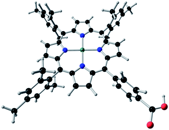 | ||
| Fig. 1 Molecular structure of the dye 5-(4-carboxylphenyl)-10,15,20-tetrakis(2,4,6-trimethylphenyl)porphyrinatozinc(II), (TPP-Zn(II)). | ||
2. Method of calculation
2.1 Molecular structure
The calculations of the electronic transitions of the TPP-Zn(II) dye were carried out using density functional theory (DFT), as implemented in the Amsterdam density functional package (ADF 2010).30 The relativistic corrections were included via the zeroth order regular approximation (ZORA) Hamiltonian.31,32 Slater type orbital (STO) basis sets with triple-z accuracy plus polarization function (TZP)33,34 for all the atoms were employed. The molecular geometry of the ground state was fully optimized via a generalized gradient approximation (GGA),35 employing the PW91 functional. The excitation energies and oscillator strengths were estimated by time dependent DFT (TD-DFT), employing the van Leeuwen–Baerends (LB94)36 potential.2.2 Surface model TiO2(110)
To model the TiO2 surface, it was represented by slabs repeated periodically, with a vacuum region of 20 Å between repeated slabs. The slabs have been constructed using a lattice parameter optimized for the bulk and reported in a previous work,37 and contain two atomic TiO2 layers which are allowed to completely relax. We chose an 8 × 2 surface model of TiO2(110), with the grids of k-points and the total amount of atoms centered at the Γ point (1 × 1 × 1) for the surface model of TiO2(110) (360 atoms, 120:Ti, 240:O). Geometrical optimization was performed using the Vienna ab initio Simulation Package (VASP 5.2 (ref. 38)) using the GGA with the exchange and the correlation energy proposed by Perdew and Wang (PW91).39 A plane-wave basis set was used to span the valence electronic states and the core electrons were represented by the projected augmented wave (PAW)40,41 method of Blöchl.Once we have completed the electronic structure calculations of the dye molecule and the metal oxide (TiO2, rutile) independently, we will focus on the TiO2–dye interaction.
The adsorption of the dye on the TiO2 surface model (Fig. 2) have been studied from density functional calculations carried out within the usual Kohn–Sham formalism, using a plane wave basis set with a cutoff of 415 eV for the kinetic energy. The PW91 form of the generalized gradient approximation (GGA) has been chosen for the exchange–correlation potential, and the effect of the atomic cores on the valence electron density has been taken into account by means of the projected augmented plane-wave (PAW) method, as implemented in the VASP 5.2 code. The Monkhorst–Pack grids42 have been used to carry out the necessary numerical integrations in the reciprocal space. A conjugated gradient algorithm with an energy criterion of 0.001 eV has been used for atomic convergence, and has ensured that the forces are smaller than 0.03 eV Å−1 in all cases.
 | ||
| Fig. 2 DSSC model consisting of the molecule adsorbed on a two-layer-slab. A hydrogen atom from the group –CO2H is transferred to the surface upon geometrical optimization (Ti atoms are represented in gray, O in red, C in black, N in blue, Zn in green, H in white). | ||
It is important to note that geometrical optimization of the dye molecules was performed using a localized basis set, while the bulk and surface model of TiO2 were calculated by using plane waves basis. Therefore the geometrical optimization using a localized basis set was followed by single-point electronic structure analysis which used a plane waves basis set to determinate all the properties using the same level of theory. In this procedure the PBE+U functional was also used, without a distinct change in energetic terms regarding PW91.
The adsorption geometries of carboxylic acid on TiO2 were considered from previous work,43 here the study of three stable positions of carboxylic acid as the anchor group between the dye and the TiO2 surface was performed.
These can be described as: (a) dissociated bridged bidentate (b) dissociated bridged chelating and (c) undissociated bridged bidentate (Fig. 3).
 | ||
| Fig. 3 Geometries of the three optimized adsorption modes for COOH–TPP-Zn(II) on TiO2(110). | ||
It is worth pointing out that calculations for the supported dye, involving exactly 467 atoms (360: Surface model, 107: TPP-Zn(II) dye) and an full relaxation of 290 atoms (TPP-Zn(II) on the first layer of the surface), have a high computational cost and thus require access to large supercomputers. On the other hand, an explicit exploration of the potential energy surface and appropriate characterization of stationary points (minima and TS structures including surface relaxation) has been carried out for supported dye in a TiO2 surface model.
Once the final geometries were obtained, the adsorption energies were calculated according to the following equation:
| Eads = ETPP-Zn(II)–TiO2(110) − (ETPP-Zn(II) + ETiO2(110)) | (1) |
To better understand the nature of the interaction of TPP-Zn(II) with the TiO2(110) surface, the electronic structure has been analyzed through different techniques. Techniques used were the Bader analysis of charge density,44 which allows one to define atomic charges in a rigorous way, the total density of state (DOS) and projected density of states (PDOS),45,46 and the analysis of the electron localization function (ELF).47,48
3. Results and discussion
3.1 Molecular structure
The molecular structure of the dye TPP-Zn(II) was fully optimized with Cs symmetry constriction. The macrocycle structure holds three meso-substituents of an electron donor nature, such as trimethylphenyl groups, and one meso-substituent that acts as an anchoring group. This substituent is a phenyl ring with a carboxylic group that is able to bond covalently to the TiO2 surface. The structure corresponds to an energetically stable geometry which has an energy minimum of the potential energy surface with all positive frequencies.Calculated geometrical parameters are reported in Table 1. In general, the Zn–N distances are very similar.
The Cα–Cm–Cα angle, where the Cm is substituted by the ring with the carboxylic group, is slightly longer with respect to the other angles. The Cβ–Cβ distances have the same value in all the pyrrolic rings. The central metal Zn(II) lies over the plane formed by the four central nitrogen atoms of the porphyrin macrocycle (Fig. 1).
3.2 Electronic structure
The isosurface plots of the frontier molecular orbitals (MOs), the higher occupied MOs (HOMO (H) and HOMO−1 (H−1)) and lower unoccupied MOs (LUMO (L) and LUMO+1 (L+1)), and the energy levels diagram are presented in Fig. 4. The HOMO, HOMO−1 and LUMO show no contribution of the peripheral meso-substituents. They are centered on the porphyrin macrocycle where the highest delocalization of the charge density is localized. The LUMO+1 orbital is composed of p-orbitals of the phenyl ring, including p-orbitals of the –CO2H group. | ||
| Fig. 4 Calculated frontier MOs isosurfaces of the TPP-Zn(II) complex. | ||
In Fig. 4 we show the energy levels at which it is possible to observe that the LUMO is the only frontier molecular orbital composed of two degenerated orbitals.
On the other hand, in the charge transfer analysis of the Zn atom, the Hirshfeld and Voronoi49 models show a charge donation from the ligands to the metallic center, since the charge of the metal in the complex is 2+ and the calculated charges are 0.465 electrons with the Hirshfeld model and 0.489 electrons using the Voronoi model. The calculated valence electronic configuration of the central metallic atom shows a charge donation to the s and p orbitals from the macrocycle, which is expected since these macrocycles are predominantly π donor ligands.
On the other hand, it is also observed that the inclusion of the anchoring group (–CO2H) in one of the substituents leads to a significant change in the composition of the frontier MOs; in fact, in the LUMO+1.
3.3 Time-dependent DFT analysis
Because the electronic coupling between the dye and the semiconductor determines the rate of electron injection and therefore the IPCE in DSSCs, and due to the fact that the stability of these cells occurs in part through a charge transfer from the dye to the semiconductor, which involves properties that are directly related to the excited states, an accurate description of the properties of the excited states of the dye is necessary. TDDFT (time dependent density functional theory)50 has proven to be a useful tool with applications in DSSCs for the study of the optical properties of the dyes.51–53Generally speaking, the UV-Vis absorption spectrum of a porphyrin is characterized by a weak Q band in the visible region and a B or Soret band at a higher energy. In fact, the latter appears in the near-UV region together with the N band. The HOMO−1, HOMO, LUMO and LUMO+1 are the MOs that are involved in the electronic transitions, and are commonly known as Gouterman orbitals.54
The excitation energies, oscillator strengths and compositions of the electronic transitions for the dye are reported in Table 2. The studied dye shows the Q broad band (which splits into three bands) in the region between 500 and 600 nm, and the B or Soret band at around 400 nm. The energy excitations are in very good agreement with the experimental data reported previously.55
| λ (nm), exp | λ (nm), calc | E (eV) | f | Composition (%) | |
|---|---|---|---|---|---|
| 595 | 592 | 2.096 | 0.015 | H → L | 61.9 |
| H−1 → L | 29.2 | ||||
| 550 | 591 | 2.100 | 0.017 | H → L | 62.5 |
| H−1 → L | 28.7 | ||||
| 502 | 480 | 2.586 | 0.006 | H → L+1 | 99.6 |
| 405 | 415 | 2.988 | 0.848 | H−1 → L | 48.3 |
| H → L | 25.1 | ||||
All the transitions are assigned as ligand-centered transitions LLCT (ligand to ligand charge transfer) and are composed mainly of the frontier molecular orbitals.
These results show that in the visible region there is a transition directed to the fragment that contains the –CO2H group in the molecule which is used to bind the macrocycle with the semiconductor surface.
3.4 –CO2H adsorption geometry
The optimized geometries for the three adsorption modes of the –CO2H anchor group (in the completed system dye-surface) are shown in Fig. 3. The nature of each optimized structure was determined by vibrational analysis, characterizing it as minimum energy on the surface energy potential. The bond lengths between the –CO2H group and the TiO2(110) surface are similar in the three evaluated positions of the –CO2H anchor group (Table 3). The differences in bond lengths for the positions of the –CO2H group and the TPP-Zn(II)–TiO2 system (Fig. 3a and b) are within 0.00–0.06 Å, while for the other system (c) the bond length between the surface and the anchor group is greater. For the carboxylic acid group the bond length of C–O is the same, except for the third conformation, where the bond length is also larger. Finally, the bond length of O–H is the same in all cases. These values indicate that, independent of the conformation of the anchor group, the bond lengths remain almost unchanged, with the exception of the (c) position (Fig. 3).| TPP-Zn(II)–TiO2 | Eads (eV) | C–C (Å) | C–O (Å) | O–Ti (Å) | O–H (Å) | ||
|---|---|---|---|---|---|---|---|
| (a) | −2.43 | 1.52 | 1.29 | 1.27 | 2.05 | 2.25 | 0.97 |
| (b) | −2.26 | 1.50 | 1.29 | 1.27 | 1.99 | 2.25 | 0.97 |
| (c) | −2.06 | 1.48 | 1.22 | 1.36 | 2.17 | 2.66 | 0.98 |
The upright orientation of the carboxylic acid perpendicular to the surface in all positions was evaluated, showing that the long axis of TPP-Zn(II) also adopts a vertical conformation relative to the surface, with a normal angle with respect to the surface.
3.5 Electronic structure and coupling in adsorbed TPP-Zn(II)
The strongest interaction between the anchor group and the TiO2(110) surface corresponds to position (a) (Fig. 3) which has an adsorption energy of 2.43 eV. The strength of the interaction is less for (b) (2.26 eV) and becomes significantly smaller for (c) (2.06 eV) in the same figure (see Table 3). This means that apparently the hydrogen atom of the anchor group prefers to be dissociated on the surface of TiO2(110), this being the most energetically stable conformation. This agrees with recent studies56 that show that the hydrogen molecule adsorbs on the pure rutile TiO2(110), and the dissociative state of H2 on TiO2(110) corresponds to the situation when both H atoms form the OH group with the low coordinated oxygen atoms on the rutile surface, as in this study.The stronger interaction of the dyes with the TiO2(110) surface results in a noticeable charge transfer of ∼1.82 e from the molecule to the surface. This can be noted from the values in Table 4, which show that for a single molecule the average charge on the oxygen atoms (−3.66 e) decreases by almost half when the molecule is anchored to the surface (−1.82 e), while the average charge on the titanium atoms in the clean surface increases when the molecule is adsorbed. This is also shown for the carbon atom in the anchor group which is adsorbed. The charge transfer seems to follow the trend in interaction energy, i.e. the adsorption is greater while the molecule transfers more charge to the surface.
| QA | ||||||
|---|---|---|---|---|---|---|
| TPP-Zn(II)–TiO2 | C | O | O | H | Ti | |
| (a) | 2.97 | −1.84 | −1.93 | 0.99 | 2.63 | 2.63 |
| (b) | 2.93 | −1.84 | −1.92 | 0.89 | 2.68 | 2.63 |
| (c) | 2.72 | −1.82 | −1.84 | 0.98 | 2.68 | 2.66 |
| Isolated | 2.69 | −3.66 | −3.66 | 0.88 | ||
| Clean surface | 2.57 | 2.60 | ||||
Ronca et al.57 mention in a recent study that when a dye binds to a semiconductor surface, the effect of the charge transfer plays an important role in the formation of chemical bond. Based on a partial integration of the electron density difference between a bound system and its separated fragments, they computationally investigated the adsorption of several prototypical organic dyes on TiO2 models. In general, they estimated to generate a net charge transfer of 0.3–0.4 electrons from the dyes to the semiconductor. In our models the net charge transferred is greater than this, and therefore we assumed that contributions due to the solvent or electrolyte that were not taken into account may overestimate the values of charge transfer, although trends continue when the –COOH group is used as the anchoring group of the TPP-Zn(II) on TiO2–rutile.
Finally, note that the polarization of the COOH–TPP-Zn(II) by the TiO2(110) surface has been seen even qualitatively in the ELF plots shown in Fig. 5. Here we show an electronic delocalization over the –CO2H anchor (yellow color) due to the polarization of the dye by the surface.
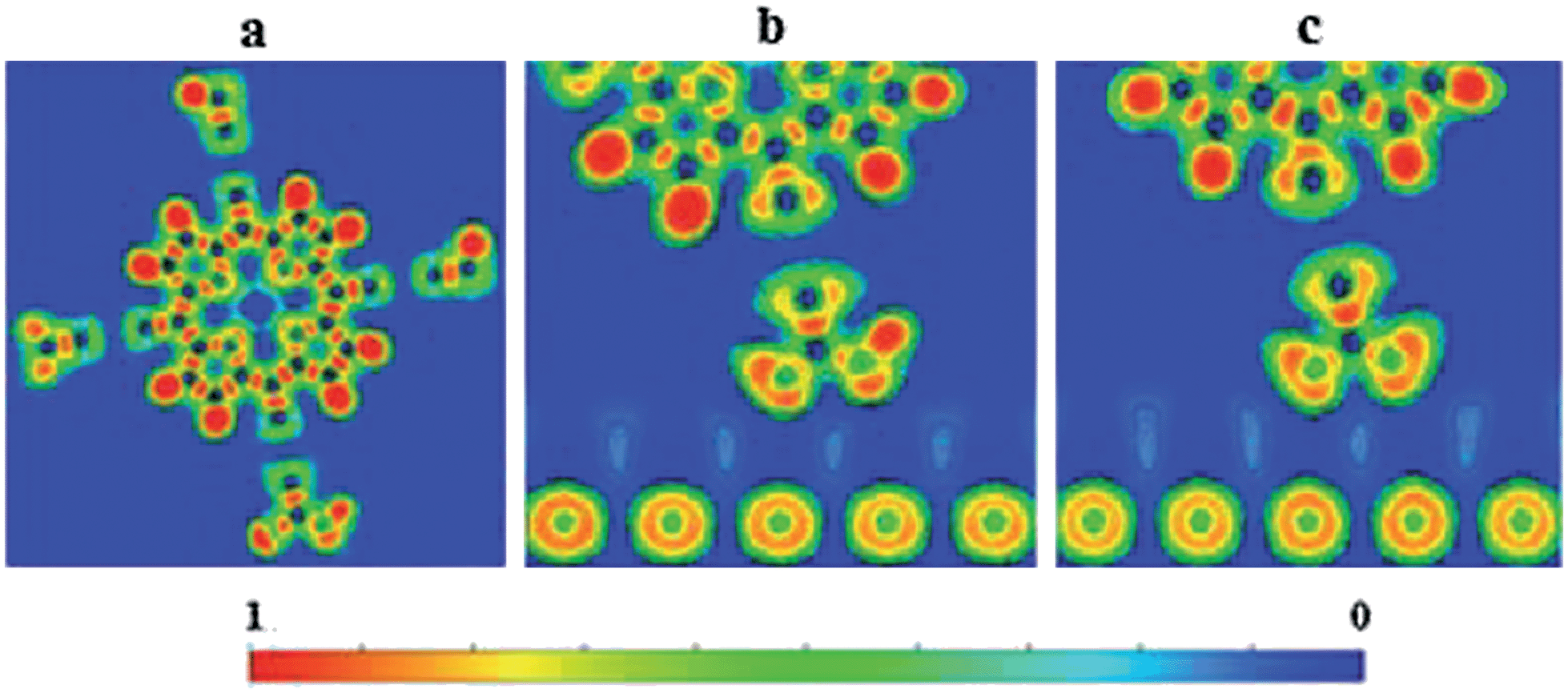 | ||
| Fig. 5 Calculated electron localization function (ELF) for: (a) a dye molecule (TPP-Zn(II)), (b and c) TPP-Zn(II)–TiO2 with the –CO2H group in the position (a and c) as in Fig. 3. | ||
With respect to the stability of the anchoring group (HCOOH) on the TiO2 (rutile and anatase), some authors have reported58,59 the chelating adsorption mode to be unstable when formic acid is adsorbed on dry and hydrated TiO2 anatase (101) surfaces. Nevertheless in this work, after geometrical optimization, we reported all the adsorption modes studied as stable. In this case, the chelating adsorption mode, position (b) Fig. 3 (which is reported as unstable by other authors), adopted as the most stable conformation the dissociated bridge bidentate mode (position (a) in the same figure) which has been reported as stable by the same authors. Therefore to study the behavior of the dye on the surface, only the more stable (a) position was characterized through the density of states.
It is important to mention that different stabilities can be obtained for the different adsorption modes depending on the employed level of theory. Nevertheless the preferred adsorption mode was bidentate bridging with one proton transferred to a nearby surface oxygen, this being the most stable adsorption mode as has been reported here and in other studies.
Fig. 6 shows the partial projected density of states (PDOS) of the TPP-Zn(II) dye and the rutile surface. The positions of the valence and conduction band edges of the TiO2 surface and the HOMO and LUMO energies of the dye are indicated.
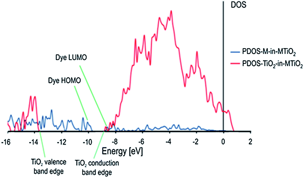 | ||
| Fig. 6 Projected density of states (PDOS) calculated for the molecule and the TiO2 surface in the complete dye–semiconductor system (MTiO2). TiO2 states are in red and the molecule (M) states are in blue. | ||
The HOMO corresponds to a dye state without coupling to the surface, separated from the TiO2 states. The LUMO is delocalized over a region of high density of TiO2 conduction band states, suggesting a strong coupling between the dye and the semiconductor states in accordance with the calculated interaction energy and charge transfer phenomenon shown in Tables 3 and 4. This facilitates electron injection.
From Fig. 7, we obtained the expected behavior for the dye-sensitized TiO2 described above; that is, the HOMO corresponds to a pure dye state (Fig. 7a), well separated from the TiO2 states, while the LUMO corresponds to the state of the slab (Fig. 7b).
 | ||
| Fig. 7 Isosurfaces of the HOMO (a) and the LUMO (b), for COOH–TPP-Zn(II) on TiO2(110) in the more stable position for the molecule. | ||
4. Conclusions
Periodic density functional calculations have been carried out to investigate the interaction between a TPP-Zn(II) dye holding a –CO2H anchoring group, and a TiO2 slab exposing a rutile (110) surface. We have first analyzed the excited state for the isolated dye and the resulting values for the energy excitations are in very good agreement with reported experimental data.In this work different adsorption positions of the –CO2H group onto the rutile TiO2(110) surface were analyzed in terms of geometry, binding energy and electronic structure. The calculations demonstrated that, independent of the conformation of the anchor group, the dye is favorably coupled to the surface. That is, it leads to a possible photocurrent energy conversion in a DSSC device. Besides, the dissociative state of the –CO2H group on the TiO2(110) corresponds to a situation where the H atom forms an OH group with the low coordinated oxygen atoms on the rutile surface (Fig. 3a and b). These results are in agreement with experimental studies which reported that the H2 molecule dissociates on the TiO2 surface, forming an OH group.
We have also analyzed the interaction of the dye with the semiconductor directly determined from calculations for the coupled system. Interestingly, a perpendicular orientation of the TPP-Zn(II) dye (relative to the TiO2 surface) was found to be the most stable position. This result agrees with the experiment where the average tilt angles and adsorption ordering of the TPP-Zn(II) molecules on the TiO2 surface were measured, showing that the more perpendicular orientation of the adsorbed TPP-Zn(II) (relative to the TiO2 surface), provides the higher concentration of long-lived electrons in the conduction band. This contributes to the increase in the photocurrent and solar cell efficiency.
It is possible to observe from Fig. 6 in the PDOS diagram that there are localized occupied states in the semiconductor band gap region, which has projection over the atoms of the dye molecule. The LUMO of the dye is delocalized in a region of high density of TiO2 conduction band states, with a LUMO energy which is lying just above the semiconductor CB (Fig. 8). This suggests a strong coupling between the dye and the semiconductor states in accordance with TD-DFT analysis, altogether with the calculated interaction energy and charge transfer analysis shown in Tables 3 and 4, which are required to induce electron injection.
 | ||
| Fig. 8 Energy level schematic diagram showing the conduction band and valence band energy for the TiO2 surface and dye molecule (TPP-Zn(II)) in the complete system COOH-TPP-Zn(II) on TiO2(110). | ||
It is important to mention that the HOMO–LUMO gap calculated for the completed system is very small. To this purpose, hybrid functionals, despite a large computational cost, are a suitable method to correct both the KS gap and the TDDFT optical gap of the substrate60 (see Table S1 in the ESI†). Nevertheless, our computational approach is able to provide considerable insight into the electronic structure of the bond system TPP-Zn(II)–TiO2 and to get insight into the anchoring modes which are very important for the coupling between the dye and the semiconductor surface. This leads to an effective photocurrent energy conversion in a DSSC device.
Acknowledgements
T.G. acknowledges financial support provided by project FONDECYT no. 3130530, a Postdoctoral grant. E.S. thanks FONDECYT no. 1130707. R.A.-P. is grateful to the Millennium Nucleus Project P07-006-F and acknowledges additional support through project FONDECYT no. 1110758 and AKA-FINLAND-CONICYT-CHILE 2012.Notes and references
- B. O'Regan and M. Grätzel, Nature, 1991, 353, 737 CrossRef CAS.
- J. M. Rehm, G. L. McLendon, Y. Nagasawa, K. Yoshijara, J. Moser and M. Grätzel, J. Phys. Chem., 1996, 100, 9577 CrossRef.
- M. Grätzel, Photoelectrochemical Cells, Nature, 2001, 414, 338 CrossRef PubMed.
- A. Hagfeldt and M. Grätzel, Chem. Rev., 1995, 95, 49 CrossRef CAS.
- H. S. Jung and J.-K. Lee, J. Phys. Chem. Lett., 2013, 4, 1682 CrossRef CAS.
- W. U. Huynh, J. J. Dittmer and A. P. Alivisatos, Science, 2002, 295, 2425 CrossRef CAS PubMed.
- N. Robertson, Angew. Chem., Int. Ed., 2006, 45, 2338 CrossRef CAS PubMed.
- H. Tian and F. Meng, Opt. Sci. Eng., 2005, 99, 313 CAS.
- M. Grätzel, Prog. Photovoltaics, 2006, 14, 429 Search PubMed.
- U. Diebold, Surf. Sci. Rep., 2003, 48, 53 CrossRef CAS.
- O. V. Prezhdo and W. R. Duncan, Annu. Rev. Phys. Chem., 2007, 58, 143 CrossRef PubMed.
- I. Nobuyuki and D. Fujita, J. Phys. Chem. C, 2012, 116, 20300 Search PubMed.
- S. E. Gledhill, B. Scott and B. A. Gregg, J. Mater. Res., 2005, 20, 3167 CrossRef CAS.
- M. Gorlov and L. Kloo, Dalton Trans., 2008, 2655 RSC.
- O. V. Chervakov, M. V. Burmistr, O. S. Sverdlikovs'ka and V. H. Shapka, Polim. Zh., 2008, 30, 5 CAS.
- A. Hagfeldt, G. Boschloo, L. Sun, L. Kloo and H. Pettersson, Chem. Rev., 2010, 110, 6595 CrossRef CAS PubMed.
- C. Chen, M. Wang, J. Li, N. Pootrakulchote, L. Alibabaei, C. Ngoc-le, J. D. Decoppet, J. Tsai, C. Grätzel, C. Wu, S. M. Zakeeruddin and M. Grätzel, ACS Nano, 2009, 3, 3103 CrossRef CAS PubMed.
- A. Yella, H.-W. Lee, H. N. Tsao, C. Yi, A. K. Chandiran, Md. K. Nazeeruddin, E. W.-G. Diau, C.-Y. Yeh, S. M. Zakeeruddin and M. Grätzel, Science, 2011, 334, 629 CrossRef CAS PubMed.
- F. Fungo, L. Otero, E. N. Durantini, J. J. Silber and L. E. Sereno, J. Phys. Chem. B, 2000, 104, 7644 CrossRef CAS.
- Y. Tachibana, S. A. Haque, I. P. Mercer, J. R. Durrant and D. R. Klug, J. Phys. Chem. B, 2000, 104, 1198 CrossRef CAS.
- P. Y. Reddy, L. Giribabu, C. Lyness, H. J. Snaith, C. Vijaykumar, M. Chandrasekharam, M. Lakshmikantam, J.-H. Yum, K. Kalyanasundaram, M. Grätzel and M. K. Nazeeruddin, Angew. Chem., Int. Ed., 2007, 46, 373 CrossRef CAS PubMed.
- J.-J. Cid, J.-H. Yum, S.-R. Jang, M. K. Nazeeruddin, E. Martínez-Ferrero, E. Palomares, J. Ko, M. Grätzel and T. Torres, Angew. Chem., Int. Ed., 2007, 46, 8358 CrossRef CAS PubMed.
- J.-H. Yum, S.-R. Jang, R. Humphry-Baker, M. Grätzel, J.-J. Cid, T. Torres and M. K. Nazeeruddin, Langmuir, 2008, 24, 5636 CrossRef CAS PubMed.
- K. Sunahara, A. Furube, R. Katoh, S. Mori, M. J. Griffith, G. G. Wallace, P. Wagner, D. L. Officer and A. J. Mozer, J. Phys. Chem. C, 2011, 115, 22084 CAS.
- B. Oviedo, X. Zarate, C. Negre, E. Schott, R. Arratia-Pérez and C. Sánchez, J. Phys. Chem. Lett., 2012, 3, 2548 CrossRef.
- T. Bessho, S. M. Zakeeruddin, C.-Y. Yeh, E. W.-G. Diau and M. Grätzel, Angew. Chem., Int. Ed., 2010, 49, 6646 CrossRef CAS PubMed.
- H. Imahori, S. Hayashi, H. Hayashi, A. Oguro, S. Eu, T. Umeyama and Y. Matano, J. Phys. Chem. C, 2009, 113, 18406–18413 CAS.
- A. Francesco, N. Martsinovich and A. Troisi, J. Phys. Chem. Lett., 2012, 3, 1531 CrossRef.
- R. Luschtinetz, J. Frenzel, T. Milek and G. Seifert, J. Phys. Chem. C, 2009, 113, 5730 CAS.
- Amsterdam Density Functional (ADF) Code, Release 2010, Vrije Universiteit, Amsterdam, The Netherlands, http://www.scm.com.
- E. van Lenthe, E. J. Baerends and J. G. Snijders, J. Chem. Phys., 1994, 101, 9783 CrossRef CAS PubMed.
- G. te Velde, F. M. Bickelhaupt, E. J. Baerends, C. Fonseca Guerra, S. J. A. van Gisbergen, J. G. Snijders and T. Ziegler, Comput. Chem., 2001, 22, 931 CrossRef CAS.
- J. G. Snijder, P. Vernooijs and E. J. Baerends, At. Data Nucl. Data Tables, 1981, 26, 48 Search PubMed.
- P. Vernooijs, J. G. Snijders, E. J. Baerends and E. J. Slater, Type Basis Functions for the Whole Periodic System, Internal Report, Free University of Amsterdam, Amsterdam, The Netherlands, 1981 Search PubMed.
- J. P. Perdew, J. A. Chevary, S. H. Vosko, K. A. Jackson, M. R. Pederson, D. J. Singh and C. Fiolhais, Phys. Rev. B: Condens. Matter Mater. Phys., 1992, 46, 6671 CrossRef CAS.
- R. van Leeuwen and E. J. Baerends, Phys. Rev. A: At., Mol., Opt. Phys., 1994, 49, 2421 CrossRef CAS.
- X. Zarate, E. Schott, T. Gomez and R. Arratia-Pérez, J. Phys. Chem. A, 2013, 117, 430 CrossRef CAS PubMed.
- G. Kresse and J. Furthmüller, Comput. Mater. Sci., 1996, 6, 15 CrossRef CAS.
- J. Perdew and Y. Wang, Phys. Rev. B: Condens. Matter Mater. Phys., 1992, 45, 13244 CrossRef.
- G. Kresse and J. Furthmüller, Phys. Rev. B: Condens. Matter Mater. Phys., 1996, 54, 11169 CrossRef CAS.
- G. Kresse and J. Hafner, Phys. Rev. B: Condens. Matter Mater. Phys., 1993, 47, 558 CrossRef CAS.
- H. J. Monkhorst and J. D. Pack, Phys. Rev. B: Solid State, 1976, 13, 5188 CrossRef.
- C. Anselmi, E. Mosconi, M. Pastore, E. Ronca and F. De Angelis, Phys. Chem. Chem. Phys., 2012, 14, 15963 RSC.
- R. F. W. Bader, Atoms in Molecules: A Quantum Theory, Oxford University Press, Oxford (UK), 1990 Search PubMed.
- A. P. Sutton, Electronic Structure of Materials, Oxford University Press, Oxford (UK), 1994 Search PubMed.
- R. Hoffmann, Solids and Surfaces: A Chemist's View of Bonding in Extended Structures, VCH Verlag, Weinhein and New York, 1988 Search PubMed.
- B. Silvi and A. Savin, Nature, 1994, 371, 683 CrossRef CAS.
- J. Contreras, A. Martín, B. Silvi and J. Recio, J. Phys. Chem. Solids, 2008, 69, 2204 CrossRef PubMed.
- R. F. Nalewajski, Phys. Chem. Chem. Phys., 2002, 4, 1710 RSC.
- M. Casida, in Recent Advances in Density Functional Methods, ed. D. P. Chong, World Scientific, Singapore, 1995 Search PubMed.
- F. De Angelis, S. Fantacci, A. Selloni, M. K. Nazeeruddin and M. Grätzel, J. Am. Chem. Soc., 2007, 129, 14156 CrossRef CAS PubMed.
- F. De Angelis, A. Tilocca and A. Selloni, J. Am. Chem. Soc., 2004, 126, 15024 CrossRef CAS PubMed.
- B. Walker and R. Gebauer, J. Chem. Phys., 2007, 127, 164106 CrossRef PubMed.
- M. Gouterman, J. Chem. Phys., 1959, 30, 1139 CrossRef CAS PubMed.
- H. Imahori, T. Umeyama and S. Ito, Acc. Chem. Res., 2009, 42, 1809 CrossRef CAS PubMed.
- X.-L. Yin, M. Calatayud, H. Qiu, Y. Wang, A. Birkner, C. Minot and Ch. Wöll, ChemPhysChem, 2008, 9, 253 CrossRef CAS PubMed.
- E. Ronca, M. Pastore, L. Belpassi, F. Tarantelli and F. De Angelis, Energy Environ. Sci., 2013, 6, 183 CAS.
- A. Vittadini, A. Selloni, F. P. Rotzinger and M. Grätzel, J. Phys. Chem. B, 2000, 104, 1300 CrossRef CAS.
- K. Srinivas, K. Yesudas, K. Bhanuprakash, V. Jayathirtha Rao and L. Giribabu, J. Phys. Chem. C, 2009, 113, 20117 CAS.
- F. De Angelis, A. Tilocca and A. Selloni, J. Am. Chem. Soc., 2004, 126, 15024 CrossRef CAS PubMed.
Footnote |
| † Electronic supplementary information (ESI) available. See DOI: 10.1039/c3ra47067a |
| This journal is © The Royal Society of Chemistry 2014 |