One-pot synthesis of carbon-coated VO2(B) nanobelts for high-rate lithium storage†
Xianhong
Rui
ab,
Daohao
Sim
a,
Chen
Xu
a,
Weiling
Liu
a,
Huiteng
Tan
a,
Kangming
Wong
a,
Huey Hoon
Hng
a,
Tuti Mariana
Lim
*bc and
Qingyu
Yan
*ade
aSchool of Materials Science and Engineering, Nanyang Technological University, 639798, Singapore. E-mail: alexyan@ntu.edu.sg; Tel: +65 6790 4583; Fax: +65 6790 9081
bSchool of Civil and Environmental Engineering, Nanyang Technological University, 639798, Singapore. E-mail: tmlim@ntu.edu.sg
cSchool of Life Sciences and Chemical Technology, Ngee Ann Polytechnic, 599489, Singapore
dEnergy Research Institute, Nanyang Technological University, 637459, Singapore
eTUM CREATE Centre for Electromobility, Nanyang Technological University, 637459, Singapore
First published on 12th December 2011
Abstract
Uniform carbon-coated single crystalline vanadium dioxide (VO2(B)@C) nanobelts were successfully prepared by using a facile one-pot hydrothermal approach. Sucrose plays a dual role in this hydrothermal process, namely as a carbon precursor for the carbon shell and, as a reductant to reduce V2O5 to VO2(B). The thickness of the carbon coating layer is tunable from 3.0 to 6.9 nm by changing the ratio of the precursors. Although a high carbon content can improve the electrical conductivity of VO2(B)@C nanobelts, a thick carbon coating layer would block the lithium ion diffusion. The optimal thickness is found to be 4.3 nm (carbon content: 6.6 wt%), where the cathode displays superior performance with highly reversible specific capacities, good cycling stabilities and excellent rate capabilities (e.g. 100 mA h g−1 at 12.4 C).
Introduction
Vanadium oxides with multiple valence states from +2 in VO to +5 in V2O5 have been extensively studied as well-known transition-metal oxides for the potential applications in catalysis,1 sensors,2 optical switching devices3 and high energy density lithium ion batteries (LIBs).4–10 For LIB applications, vanadium oxides (e.g.V2O5, V6O13 and VO2(B)etc.) offer the advantages of high capacity, simple synthesis procedure, low cost and being abundant with respect to the commercial cathode LiCoO2.7,11–13V2O5 is known to undergo a series of phase transformation during Li+ intercalation/deintercalation processes, giving theoretical capacities up to 294 (x = 2 in LixV2O5) and 442 mA h g−1 (x = 3 in LixV2O5). However, V2O5 suffers from a large irreversible capacity at a deep discharge/charge depth (x > 1 in LixV2O5), and thus affects the battery cycling performance.7 Beside V2O5, vanadium oxides with the nominal stoichiometry of VO2+x (0 ≤ x ≤ 0.33), e.g.VO2(B), V6O13, V4O9 and V3O7, can also serve as promising cathode materials for LIBs.7,14 Among them, VO2(B) is found to show a better cycling stability than V2O5. For example, VO2(B) nanofiber aerogels prepared through a sol–gel method exhibited a capacity retention of ∼80% between 4.0 and 1.5 V at C/8 after 20 cycles, while V2O5 nanorods obtained by annealing the VO2(B) aerogels under air only attained a capacity retention of ∼55% under the same testing conditions.7 This is mainly due to the higher structural stability of VO2(B), which arises from the increased edge sharing and the consequent resistance to lattice shearing during cycling,4 and emerging of undesired agglomerate irregular V2O5 particles during the annealing process. The capacity retention of V2O5 based electrodes can be improved by a sol–gel route,15,16e.g., showing a value of ∼75% at C/20 after 10 cycles15.To develop high-performance VO2(B) based cathodes, especially at high current densities, one-dimensional (1D) nanowires or nanobelts are the most favourable as they can offer a range of unique advantages over their traditional counterparts including large interfacial contact area between the electrode and electrolyte, short Li+ transport distance, efficient 1D electron transport pathways and facile strain relaxation upon electrochemical cycling.6,17,18 For example, an electrode platform18 was developed to enable silicon nanowires to grow directly onto the current collector to accommodate the large volume change and to avoid capacity fading. Similar enhanced Li storage properties could also be obtained in 1D VO2(B) nanofibers,7nanorods,19nanowires,20 and nanobelts.21,22 Although the VO2(B) nanostructures were reported to show improved cyclability at relatively low current densities (e.g. capacity retention: 75% during the first 100 cycles at 1 C)21, their rate capabilities are still not satisfactory. For example, a VO2(B) nanobelts/multiwall carbon nanotube composite21 exhibited capacity retentions of 77% (0.3 C), 65% (1 C), 49% (3 C) and 39% (5 C), respectively, on the basis of the 2nd discharge capacity (327 mA h g−1) at 0.1 C. Such performance is significantly lower than other reported high-performance cathodes such as flower-shaped LiFePO4/C/polypyrrole microspheres,23 with capacity retentions of 92% (2 C), 81% (5 C) and 63% (10 C), respectively, based on the 2nd discharge capacity of 136 mA h g−1 at 0.5 C. Hence, further performance improvement on VO2(B) based cathode electrodes is highly desired.
Coating active materials with a conductive and elastic carbon layer is a simple and effective strategy to improve the rate capability and cycling stability of electrodes, where the carbon coating can effectively (1) enhance the kinetics of charge transfer, (2) buffer the strain caused by structural or volume changes and (3) prevent the aggregation of active materials during cycling.24–32 In this regard, cathodes with superior performance for LIBs have been successfully developed by coating a thin carbon layer onto the surface of LiCoO2,27LiMn2O4,28LiFePO429,30 and Li3V2(PO4)3.31,32 However, a thick carbon coating layer would hinder the Li+ diffusion.32,33 Therefore, the thickness of the carbon layer needs to be adjusted to achieve optimized Li storage performance.
Herein, we report a facile one-pot hydrothermal approach to synthesize uniform carbon-coated VO2(B) (denoted as VO2(B)@C) nanobelts. The thickness of carbon coating layer is controlled by changing the concentration of the precursors, which can affect the Li storage performance of the VO2(B)@C samples. The VO2(B)@C samples with different thicknesses of the carbon layer show high specific capacities and stable cyclability at a current density of 100 mA g−1 (0.6 C). It is found that a thick carbon layer may decrease the apparent diffusion coefficient of lithium ions although it can increase the electrical conductivity and buffer the structural strain during the lithiation process. The VO2(B)@C cathode with a carbon content of 6.6 wt% (e.g. the thickness of carbon shell is ∼4.3 nm) shows an optimized Li ion storage performance at high current densities, achieving a highly reversible discharge capacity of 100 mA h g−1 at a current density of 2000 mA g−1 (12.4 C).
Experimental
Synthesis of VO2(B)@C nanobelts
In a typical procedure, 50 mg V2O5 (Alfa Aesar) and 10 mg sucrose (C12H22O11, Sigma-Aldrich) were put in 40 mL distilled water under ultrasonication to give a yellow suspension. Successively, the suspension was transferred to a 50 mL autoclave and kept in an oven at 180 °C for 24 h. After cooling to room temperature, a black product was collected and washed with distilled water and ethanol solution several times, and then dried in a vacuum oven at 70 °C for 12 h. During the hydrothermal process, sucrose serves as a carbon precursor for the carbon shell as well as a reductant to reduce V2O5 to VO2(B), since the sucrose possesses the same hydroxyl group as the alcohol.34 To obtain a thicker carbon coating layer, the quantity of sucrose was sequentially increased to 20, 30 and 40 mg.Materials characterization
X-Ray powder diffraction (XRD) patterns were recorded on a Bruker AXS D8 advance X-ray diffractometer at the 2θ range of 10 to 60° using Cu Kα radiation. The morphology of the VO2(B)@C samples was investigated by using a field-emission scanning electron microscopy (FESEM) system (JEOL, Model JSM-7600F), and the nanostructure was characterized by using a transmission electron microscopy (TEM) system (JEOL, Model JEM-2010) operating at 200 kV. Thermogravimetry analysis was carried out from room temperature to 550 °C at a heating rate of 10 K min−1 in air using TGA Model Q500. Raman spectra were obtained by WITec CRM200 confocal Raman microscopy system at a laser wavelength of 488 nm and a spot size of 0.5 mm. X-Ray photoelectron spectroscopy (XPS) measurement was performed on VG Escalab 250 spectrometer using an Al Kα 1846.6 eV anode.Electrochemical measurements
The coin-type cells were assembled in an argon-filled glove-box, where both moisture and oxygen levels were less than 1 ppm. The cathodes were fabricated by mixing VO2(B)@C nanobelts, carbon black and poly(vinyldifluoride) (PVDF) at a weight ratio of 70![[thin space (1/6-em)]](https://www.rsc.org/images/entities/char_2009.gif) :20:10 in N-methylpyrrolidone (NMP) solvent. The resulting mixture was then pasted onto the aluminum foil and punched into small disks (Ø = 14 mm). The mass loading was around 2.0 mg. Lithium foils were used as anodes and the electrolyte solution was made of 1 M LiPF6 in ethylene carbonate (EC)/dimethyl carbonate (DMC) (1/1, w/w). The cells were tested on a NEWARE multi-channel battery test system with galvanostatic charge and discharge in the voltage range 4.0–2.0 V. For current density, 1 C equals 161 mA g−1 based on the theoretical capacity (161 mA h g−1) of VO2(B) between 4.0 and 2.0 V. The capacity values in this paper were estimated based on the bare VO2(B) without the amorphous coating carbon and carbon black. The electrochemical impedance spectra (frequency range: 0.001∼105 Hz) were performed with an electrochemical workstation (CHI 660C). Cyclic voltammetry of VO2(B)@C electrodes in coin-type cells were performed with a Solartron analytical equipment (model 1470E) at different scan rates.
:20:10 in N-methylpyrrolidone (NMP) solvent. The resulting mixture was then pasted onto the aluminum foil and punched into small disks (Ø = 14 mm). The mass loading was around 2.0 mg. Lithium foils were used as anodes and the electrolyte solution was made of 1 M LiPF6 in ethylene carbonate (EC)/dimethyl carbonate (DMC) (1/1, w/w). The cells were tested on a NEWARE multi-channel battery test system with galvanostatic charge and discharge in the voltage range 4.0–2.0 V. For current density, 1 C equals 161 mA g−1 based on the theoretical capacity (161 mA h g−1) of VO2(B) between 4.0 and 2.0 V. The capacity values in this paper were estimated based on the bare VO2(B) without the amorphous coating carbon and carbon black. The electrochemical impedance spectra (frequency range: 0.001∼105 Hz) were performed with an electrochemical workstation (CHI 660C). Cyclic voltammetry of VO2(B)@C electrodes in coin-type cells were performed with a Solartron analytical equipment (model 1470E) at different scan rates.
Results and discussion
The crystal structure of the as-prepared samples obtained at different weight ratio of V2O5 to sucrose (herein known as IV2O5:sucrose) in the hydrothermal process was examined by X-ray diffraction (XRD). Fig. 1 reveals that all the reflection peaks of the four samples can be indexed to the monoclinic VO2(B) phase (space group: C2/m, JCPDS 31-1438). No detectable crystalline carbon peaks can be observed. It has been reported that the carbon derived from sucrose (or glucose) under hydrothermal conditions is amorphous.25,35,36 The nature of the carbon coating of the VO2(B) products was studied using Raman spectroscopy (see ESI,† Fig. S1a). Two characteristic bands of carbonaceous materials were detected at 1370 cm−1 (D-band) and at 1600 cm−1 (G-band), which agree well with those of amorphous carbon.23,37 The carbon structure was further analyzed by X-ray photoelectron spectroscopy (XPS) C 1s spectrum (see ESI,† Fig. S1b). The spectrum was fitted with two components, centered at 284.5 and 285.7 eV, which correspond to sp2 and sp3 bonded carbon, respectively. The ratio of sp2 to sp3 was then determined to be as high as ∼2.5, which is comparable to that of amorphous carbon thin films prepared by magnetron sputtering and cathodic arc deposition,38 implying a relatively high electronic conductivity. | ||
| Fig. 1 XRD patterns of the as-prepared samples obtained at different IV2O5:sucrose in the hydrothermal process. (a) IV2O5:sucrose = 5.00, (b) IV2O5:sucrose = 2.50, (c) IV2O5:sucrose = 1.67 and (d) IV2O5:sucrose = 1.25. | ||
To determine the carbon content in the VO2(B)@C composites, thermogravimetric analysis (TGA) was carried out in air (see Fig. 2). The weight loss of 1.7% below 100 °C is attributed to the evaporation of free water and physically adsorbed water. The weight changes in the temperature range 100–450 °C are ascribed to the burning-out of amorphous carbon (weight loss) and oxidization of VO2 to V2O5 (weight gain). Based on the total weight changes, the carbon contents are estimated to be 4.2 wt%, 6.6 wt%, 8.4 wt% and 9.6 wt% for VO2(B)@C composites prepared with IV2O5:sucrose = 5.00–1.25, respectively. Thus, these four samples are named as VO2(B)@C (4.2 wt%), VO2(B)@C (6.6 wt%), VO2(B)@C (8.4 wt%) and VO2(B)@C (9.6 wt%).
 | ||
| Fig. 2 TGA curves of VO2(B)@C composites prepared at different IV2O5:sucrose values, (a) = 5.00, (b) = 2.50, (c) = 1.67 and (d) = 1.25. | ||
The field emission scanning electron microscopy (FESEM) images show that the sample prepared with IV2O5:sucrose = 5.00 is made up of nanobelts (see Fig. 3a–c) of 1–2 μm in length and 120–160 nm in width with a thickness of ∼25 nm. Decreasing the IV2O5:sucrose values during the hydrothermal process from 5.00 to 2.50 and 1.67 does not lead to obvious changes in the nanobelt shape except for the slight decrease in the length (see Fig. 3d–i). Further decreasing IV2O5:sucrose to 1.25 results in a significant decrease in the length of the sample to 200∼500 nm, making the sample nanosheets (see Fig. 3j–l). This is mainly attributed to the binding of the sucrose molecules onto the surface of VO2(B) nanocrystals and hence confines their growth under high sucrose concentration. Thus, the sucrose does not only act as the carbon source but also as an effective surfactant similar to the synthesis of other reported nanocrystals.35,39 Here, the formation of the VO2(B)@C nanobelts is mainly ascribed to the anisotropic bonding of its layered structure, resulting in the faster growth along the [010] direction and the slower growth along [001] direction.40 Meanwhile, the 1D soft templates formed by the stacking of the sucrose molecules may also contribute to the growth of 1D VO2(B) nanocrystals.39
 | ||
| Fig. 3 Representative FESEM images of VO2(B)@C nanobelts. (a–c) VO2(B)@C (4.2 wt%), (d–f) VO2(B)@C (6.6 wt%), (g–i) VO2(B)@C (8.4 wt%) and (j–l) VO2(B)@C (9.6 wt%). Representative high-magnification FESEM images of (b, e, h and k) and (c, f, i and l) are the magnified view of VO2(B)@C nanobelts to show the width and thickness of the nanobelts, respectively. | ||
The nanostructure of VO2(B)@C nanobelts was further examined by using the high resolution transmission electron microscopy (HRTEM). Fig. 4 reveals that the VO2(B) nanocrystals are coated with a layer of amorphous carbon, which forms the VO2(B)@carbon core–shell structure. Here, the carbon shell forms through the carbonization of the sucrose under hydrothermal conditions. The thickness of the carbon shell can be simply tuned by changing the values of IV2O5:sucrose during the hydrothermal process. The thickness of the carbon layer increases from ∼3.0 to ∼6.9 nm when IV2O5:sucrose is decreased from 5.00 to 1.25 (see Fig. 4). The lattice fringes observed from the HRTEM images indicate the single crystalline nature of the VO2(B) nanobelts. The observed interplanar spacing of 0.34 nm in the HRTEM images of these four samples agrees well with the d value of the (110) plane of the monoclinic VO2(B) (JCPDS 31-1438). The inset in Fig. 4d is the indexed fast Fourier transform (FFT) pattern of Fig. 4d.
 | ||
| Fig. 4 Representative HRTEM images of VO2(B)@C nanobelts. (a) VO2(B)@C (4.2 wt%), (b) VO2(B)@C (6.6 wt%), (c) VO2(B)@C (8.4 wt%) and (d) VO2(B)@C (9.6 wt%). The inset in Fig. 4d is the FFT pattern of Fig. 4d. | ||
To study the Li-ion storage properties of VO2(B)@C nanobelts, a series of electrochemical measurements were carried out based on the half cell configuration.41–43Fig. 5a shows the initial galvanostatic discharge (Li+ insertion) and charge (Li+ extraction) voltage profiles of the VO2(B)@C electrodes at a current density of 100 mA g−1 (0.6 C) between 4.0 and 2.0 V vs.Li+/Li. A typical long plateau at around 2.5 V is clearly observed in the discharge curves, which corresponds to a phase transition of crystalline VO2(B) to Li0.5VO2(B) and the corresponding electrochemical reaction is written as:5
| VO2 + 0.5Li+ + 0.5e− → Li0.5VO2 | (1) |
Half lithium insertion into VO2 yields a theoretical capacity of 161 mA h g−1. This reaction is highly reversible as indicated by the long plateau at ∼2.6 V in the subsequent charge process. As shown in Fig. 5a, the VO2(B)@C (4.2 wt%), VO2(B)@C (6.6 wt%), VO2(B)@C (8.4 wt%) and VO2(B)@C (9.6 wt%) electrodes depict initial discharge capacities of 160, 161, 159 and 158 mA h g−1 with the subsequent charge capacities of 160, 161, 159 and 158 mA h g−1, respectively, indicating no irreversible capacity loss (e.g. the coulombic efficiency is ∼100%). During the 50th cycle, the discharge capacities are 125, 128, 120 and 116 mA h g−1 for VO2(B)@C (4.2 wt%), VO2(B)@C (6.6 wt%), VO2(B)@C (8.4 wt%) and VO2(B)@C (9.6 wt%) electrodes (see Fig. 5b), which are 78%, 80%, 76% and 73% of the initial capacity, respectively. Although initial capacities are relatively lower as compared to flexible free-standing VO2(B) nanobelt films (218.7 mA h g−1 at current density of 10 mA g−1 in the voltage range 4.0–1.5 V),22 these cycling performances are much better than that electrode (53% of capacity retention at 50 mA g−1 during the first 50 cycles) as well as other reported VO2(B) and V2O5 cathodes, e.g., 50% of capacity retention for VO2(B) nanorods between 3.44 and 1.5 V at 0.1 C during the 17 cycles,44 68% of capacity retention for VO2(B) nanowires at 50 mA g−1 (0.3 C) between 3.2 and 2.0 V during the first 50 cycles20 and 61% of capacity retention for V2O5 submicron spheres at 0.125 C between 3.8 and 1.8 V during the first 35 cycles.45
Good rate capability is one of the keys in developing high power/fast charging lithium ion batteries. The cycling responses of the VO2(B)@C electrodes at different C rates are evaluated and are shown in Fig. 5c. Among the four types of cathodes, the VO2(B)@C (6.6 wt%) electrode shows the best rate capability, delivering discharge capacities of 157, 155, 146 and 136 mA h g−1 during the 2nd cycle at current densities of 200 (1.2 C), 500 (3.1 C), 800 (5.0 C) and 1000 mA g−1 (6.2 C), respectively. Even at a very high current density of 2000 mA g−1 (12.4 C), the VO2(B)@C (6.6 wt%) electrode can still achieve a high specific capacity of 100 mA h g−1 during the 2nd cycle. The retention of the rate capacity is calculated to be 99% (3.1 C), 93% (5.0 C), 87% (6.2 C) and 64% (12.4 C) on the basis of the capacity value of 157 mA h g−1 at 1.2 C. The other three electrodes exhibit relatively low specific capacities, especially at high C rates, e.g. showing discharge capacities of 90, 69 and 41 mA h g−1 at 12.4 C for VO2(B)@C (4.2 wt%), VO2(B)@C (8.4 wt%) and VO2(B)@C (9.6 wt%), respectively. The difference of the rate capabilities of these four cathodes is verified by the electrochemical impedance spectra (see Fig. 5d). The VO2(B)@C (6.6 wt%) cathode shows the smallest radius of semi-circle in the Nyquist plots as compared to the other three, indicating the smallest charge-transfer resistance and the correspondence fastest kinetics of the Faradic reaction.46
 | ||
| Fig. 5 Cathode performance of VO2(B)@C nanobelts in the voltage range 4.0–2.0 V. (a) Initial galvanostatic charge–discharge voltage profiles at a current density of 100 mA g−1. (b) Cycling performance at a current density of 100 mA g−1. (c) Discharge capacities of VO2(B)@C electrodes at various current densities of 200 to 2000 mA g−1. (d) Electrochemical impedance spectra of VO2(B)@C electrodes measured at the 4th fully discharged state. The high-middle frequency semicircle represents the charge-transfer process and a straight slopping line at low frequencies corresponds to Li+ diffusion in VO2(B)@C electrodes known as Warburg impedance. | ||
It is interesting to find out that the VO2(B)@C (6.6 wt%) electrode shows the best rate capabilities among these four samples. Generally, a high carbon content should improve the electrical conductivity of the VO2(B)@C composites. However, a thick layer of carbon coating may also block the lithium ion diffusion.32,33 To verify this, cyclic voltammetry (CV) was used to estimate the apparent diffusion coefficient of lithium ions (DLi+) in VO2(B)@C nanobelt cathodes. Fig. S2 (ESI†) shows the CV plots of VO2(B)@C nanobelts with different scan rates: 0.1, 0.2 0.3 and 0.5 mV s−1. A pair of redox peaks is clearly seen in the CV curves, corresponding to the phase transition between VO2 and Li0.5VO2 as indicated in eqn (1), which is consistent with the potential plateaus observed in the charge–discharge curves (see Fig. 5a). As shown in Fig. 6, it is found that the current of the oxidation peaks (ip) has a linear relationship with the square root of scan rate (ν1/2), which is typical of the equilibrium behaviour of an intercalation type electrode.46 If the charge transfer at the interface is fast enough and the limiting step of the Li transfer is the lithium diffusion in the electrode, the relationship of the peak current and the CV sweep rate is given as:
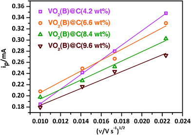 | ||
| Fig. 6 The relationship of the oxidation peak current (ip) and the square root of scan rate (v1/2). | ||

| (2) |
| C Li+= m/(NA/V) | (3) |
Conclusions
We have developed a facile one-pot hydrothermal approach to synthesize uniform carbon-coated VO2(B) nanobelts. The thickness of carbon coating layer is tunable from 3.0 to 6.9 nm by changing the ratio of the precursors. The electrochemical test shows that the VO2(B)@C is promising as a high-power cathode material for LIBs. For example, the VO2(B)@C electrode with a 4.3 nm carbon layer (e.g.carbon content: 6.6 wt%) depicts high specific capacities, good cycling stabilities and excellent rate capabilities (e.g. 100 mA h g−1 at 12.4 C).Acknowledgements
The authors gratefully acknowledge AcRF Tier 1 RG 31/08 of MOE (Singapore), NRF2009EWT-CERP001-026 (Singapore), Singapore Ministry of Education (MOE2010-T2-1-017), A*STAR SERC grant 1021700144 and Singapore MPA 23/04.15.03 RDP 009/10/102 and MPA 23/04.15.03 RDP 020/10/113 grant.References
- N. Magg, J. B. Giorgi, M. M. Frank, B. Immaraporn, T. Schroeder, M. Baumer and H. J. Freund, J. Am. Chem. Soc., 2004, 126, 3616 CrossRef CAS.
- C. M. Leroy, M. F. Achard, O. Babot, N. Steunou, P. Masse, J. Livage, L. Binet, N. Brun and R. Backov, Chem. Mater., 2007, 19, 3988 CrossRef CAS.
- E. E. Chain, Appl. Opt., 1991, 30, 2782 CAS.
- C. Tsang and A. Manthiram, J. Electrochem. Soc., 1997, 144, 520 CAS.
- B. Zachauchristiansen, K. West and T. Jacobsen, Mater. Res. Bull., 1985, 20, 485 CrossRef CAS.
- X. H. Rui, J. X. Zhu, W. L. Liu, H. T. Tan, D. H. Sim, C. Xu, H. Zhang, J. Ma, H. H. Hng, T. M. Lim and Q. Y. Yan, RSC Adv., 2011, 1, 117 RSC.
- H. Q. Li, P. He, Y. G. Wang, E. Hosono and H. S. Zhou, J. Mater. Chem., 2011, 21, 10999 RSC.
- E. S. Takeuchi, K. J. Takeuchi and A. C. Marschilok, Encyclopedia of Electrochemical Power Sources, Elsevier, Amsterdam, 2009, 4, 100 Search PubMed.
- L. Q. Mai, X. Xu, L. Xu, C. H. Han and Y. Z. Luo, J. Mater. Res., 2011, 26, 2175 Search PubMed.
- A. S. Tracey, G. R. Willsky and E. S. Takeuchi, Vanadium: Chemistry, Biochemistry Pharmacology and Practical Applications 2007, CRC Press: Boca Raton, FL, 221–240 Search PubMed.
- C. Z. Wu, J. Dai, X. D. Zhang, J. L. Yang, F. Qi, C. Gao and Y. Xie, Angew. Chem. Int. Ed., 2010, 49, 134 CAS.
- Z. Gui, R. Fan, W. Q. Mo, X. H. Chen, L. Yang, S. Y. Zhang, Y. Hu, Z. Z. Wang and W. C. Fan, Chem. Mater., 2002, 14, 5053 CrossRef CAS.
- F. Sediri and N. Gharbi, Mater. Lett., 2009, 63, 15 CrossRef CAS.
- D. W. Murphy, P. A. Christian, F. J. Disalvo, J. N. Carides and J. V. Waszczak, J. Electrochem. Soc., 1981, 128, 2053 CAS.
- C.-Y. Lee, A. C. Marschilok, A. Subramanian, K. J. Takeuchi and E. S. Takeuchi, Phys. Chem. Chem. Phys., 2011, 13, 18047 RSC.
- A. Marschilok, C. Y. Lee, A. Subramanian, K. J. Takeuchi and E. S. Takeuchi, Energy Environ. Sci., 2011, 4, 2943 RSC.
- H. Q. Li, T. Y. Zhai, P. He, Y. G. Wang, E. Hosono and H. S. Zhou, J. Mater. Chem., 2011, 21, 1780 RSC.
- C. K. Chan, H. L. Peng, G. Liu, K. McIlwrath, X. F. Zhang, R. A. Huggins and Y. Cui, Nat. Nanotechnol., 2008, 3, 31 CrossRef CAS.
- Z. J. Chen, S. K. Gao, L. L. Jiang, M. D. Wei and K. M. Wei, Mater. Chem. Phys., 2010, 121, 254 CrossRef CAS.
- G. Armstrong, J. Canales, A. R. Armstrong and P. G. Bruce, J. Power Sources, 2008, 178, 723 CrossRef CAS.
- M. M. Rahman, J. Z. Wang, N. H. Idris, Z. X. Chen and H. K. Liu, Electrochim. Acta, 2010, 56, 693 Search PubMed.
- J. J. Huang, X. F. Wang, J. F. Liu, X. M. Sun, L. Wang and X. M. He, Int. J. Electrochem. Sci., 2011, 6, 1709 Search PubMed.
- C. W. Sun, S. Rajasekhara, J. B. Goodenough and F. Zhou, J. Am. Chem. Soc., 2011, 133, 2132 CrossRef CAS.
- Z. Y. Wang, J. S. Chen, T. Zhu, S. Madhavi and X. W. Lou, Chem. Commun., 2010, 46, 6906 RSC.
- X. M. Sun and Y. D. Li, Angew. Chem., Int. Ed., 2004, 43, 597 CrossRef.
- L. J. Zhi, Y. S. Hu, B. El Hamaoui, X. Wang, I. Lieberwirth, U. Kolb, J. Maier and K. Mullen, Adv. Mater., 2008, 20, 1727 CrossRef CAS.
- Q. Cao, H. P. Zhang, G. J. Wang, Q. Xia, Y. P. Wu and H. Q. Wu, Electrochem. Commun., 2007, 9, 1228 CrossRef CAS.
- A. R. Han, T. W. Kim, D. H. Park, S. J. Hwang and J. H. Choy, J. Phys. Chem. C, 2007, 111, 11347 CrossRef CAS.
- Y. G. Wang, Y. R. Wang, E. J. Hosono, K. X. Wang and H. S. Zhou, Angew. Chem., Int. Ed., 2008, 47, 7461 CrossRef CAS.
- S. W. Oh, S. T. Myung, S. M. Oh, K. H. Oh, K. Amine, B. Scrosati and Y. K. Sun, Adv. Mater., 2010, 22, 4842 CrossRef CAS.
- H. Huang, S. C. Yin, T. Kerr, N. Taylor and L. F. Nazar, Adv. Mater., 2002, 14, 1525 CrossRef CAS.
- X. H. Rui, C. Li, J. Liu, T. Cheng and C. H. Chen, Electrochim. Acta, 2010, 55, 6761 Search PubMed.
- N. J. Yun, H. W. Ha, K. H. Jeong, H. Y. Park and K. Kim, J. Power Sources, 2006, 160, 1361 CrossRef CAS.
- H. M. Liu, Y. G. Wang, K. X. Wang, E. Hosono and H. S. Zhou, J. Mater. Chem., 2009, 19, 2835 RSC.
- R. Yang, W. Zhao, J. Zheng, X. Z. Zhang and X. G. Li, J. Phys. Chem. C, 2010, 114, 20272 CrossRef CAS.
- J. X. Zhu, T. Sun, H. H. Hng, J. Ma, F. Y. C. Boey, X. W. Lou, H. Zhang, C. Xue, H. Y. Chen and Q. Y. Yan, Chem. Mater., 2009, 21, 3848 CrossRef CAS.
- A. Odani, V. G. Pol, S. V. Pol, M. Koltypin, A. Gedanken and D. Aurbach, Adv. Mater., 2006, 18, 1431 CrossRef CAS.
- S. T. Jackson and R. G. Nuzzo, Appl. Surf. Sci., 1995, 90, 195 CrossRef CAS.
- Q. Y. Yan, H. Chen, W. W. Zhou, H. H. Hng, F. Y. C. Boey and J. Ma, Chem. Mater., 2008, 20, 6298 CrossRef CAS.
- J. F. Liu, Q. H. Li, T. H. Wang, D. P. Yu and Y. D. Li, Angew. Chem., Int. Ed., 2004, 43, 5048 CrossRef CAS.
- J. X. Zhu, T. Zhu, X. Z. Zhou, Y. Y. Zhang, X. W. Lou, X. D. Chen, H. Zhang, H. H. Hng and Q. Y. Yan, Nanoscale, 2011, 3, 1084 RSC.
- J. X. Zhu, Y. K. Sharma, Z. Y. Zeng, X. J. Zhang, M. Srinivasan, S. Mhaisalkar, H. Zhang, H. H. Hng and Q. Y. Yan, J. Phys. Chem. C, 2011, 115, 8400 CrossRef CAS.
- S. Saadat, Y. Y. Tay, J. X. Zhu, P. F. Teh, S. Maleksaeedi, M. M. Shahjamali, M. Shakerzadeh, M. Srinivasan, B. Y. Tay, H. H. Hng, J. Ma and Q. Y. Yan, Chem. Mater., 2011, 23, 1032 CrossRef CAS.
- C. V. S. Reddy, E. H. Walker, S. A. Wicker, Q. L. Williams and R. R. Kalluru, Curr. Appl. Phys., 2009, 9, 1195 CrossRef.
- Y. Chen, H. Liu and W. L. Ye, Scr. Mater., 2008, 59, 372 CrossRef CAS.
- X. H. Rui, Y. Jin, X. Y. Feng, L. C. Zhang and C. H. Chen, J. Power Sources, 2011, 196, 2109 Search PubMed.
Footnote |
| † Electronic Supplementary Information (ESI) available: Raman spectra and XPS of VO2(B)@C composites and CV plots of VO2(B)@C electrodes at various scan rates. See DOI: 10.1039/c1ra00698c/ |
| This journal is © The Royal Society of Chemistry 2012 |