Hydrogen production by graphdiyne (CnH2n−2)-based graphdiyne/CuI/NiMn(LDHs) double S-scheme heterojunctions
Zhenkun
Liu
and
Zhiliang
Jin
 *
*
School of Chemistry and Chemical Engineering, Ningxia Key Laboratory of Solar Chemical Conversion Technology, Key Laboratory for Chemical Engineering and Technology, State Ethnic Affairs Commission, North Minzu University, Yinchuan, 750021, P. R. China. E-mail: zl-jin@nun.edu.cn
First published on 23rd December 2022
Abstract
Graphdiyne (GDY), as the latest carbon material, has demonstrated exceptional performance in a number of applications. The good conduction performance of GDY may promote the electron transfer and greatly improve the low separation rate of electron–hole pairs caused by the slow electron transfer rate. Herein, CuI–GDY was obtained by the cross-coupling method, and CuI–GDY/NiMn(LDHs) composite catalysts were obtained by a simple solvothermal method. The lamellar structure of NiMn(LDHs) is endowed with a large specific surface area and a rough surface. The double S-scheme heterojunctions constructed between the composite catalysts accelerates the electron transfer rate, allowing more photogenerated electrons to participate in the hydrogen precipitation reaction. The good stability of GDY is brought to the composite catalyst after compounding and makes the hole–electron pair compounding rate of the composite catalyst decrease. Thus, the composite catalysts maintained good hydrogen precipitation activity even after 20 hours of cycling, and the hydrogen precipitation activity was further improved. The hydrogen production activity of the composite catalyst (1094.6 μmol g−1 h−1) was increased by 11.24, 8.80, 20.99, 3.78 and 2.58 times when compared to pure GDY, CuI–GDY, CuI, NiMn(LDHs) and NiMn(LDHs)–CuI, respectively. Furthermore, NiMn(LDHs)-x in the dye sensitization system shows strong stability. This work provides a new perspective for GDY modification on semiconductor bandgap and the application of GDY in the photocatalytic hydrogen generation reaction.
1. Introduction
It is well known that traditional fossil fuel is unrenewable.1,2 With the increasing detrimental growth of the global greenhouse effect, it is critical to seek clean energy to replace fossil energy. As the cleanest energy, hydrogen is undoubtedly the best choice.3–6 However, hydrogen production from water cracking requires a huge energy amount in kinetics to break the barrier. Thus, efficient, stable and economical photocatalysts are needed to reduce the activation energy to produce hydrogen.7–9 Among them, non-metallic carbon-based materials are very attractive because of their environmental friendliness, abundance, diversity and low cost. One of the most representative examples is graphitic carbon nitride, which has received wide attention for its simple synthesis, stable structure and chemical properties, and wide range of light absorption.10,11 However, it also has obvious drawbacks, exhibiting poor photocatalytic performance due to the low utilization of sunlight and rapid compounding of photoexcited carriers.12,13 Similarly, other photocatalysts tend to have some disadvantages, such as an electron–hole complexation that is too fast and band gaps that are too narrow or wide.14–17 To solve these drawbacks, techniques such as constructing heterojunctions,18,19 metal doping, and nonmetal modification can often be used to suppress drawbacks, such as electron–hole pair complexation. Thus, the photocatalyst is built towards better photocatalytic hydrogen evolution activity.20,21 In recent years, S-scheme heterojunctions have been of increasing interest.22,23 This is because when S-scheme heterojunctions are established between different catalysts, a built-in electric field is formed inside the catalyst. The built-in electric field, Coulomb force and band edge bending at the catalyst interface will induce more useful electrons to participate in the reduction reaction.24As a new member of carbon materials, GDY is composed of sp and sp2 hybrid carbon networks. It can be as thin as a single atomic layer, particularly when it was first synthesized chemically in situ on copper foil by the Li group in 2010.25–27 Due to the properties of GDY itself, such as abundant chemical bonding, high conjugation, oversized π structure and high electron mobility, it has great potential in the fields of catalysis, electricity, optics, and information.16,25
GDY has unlimited generation space and can be grown on any substrate. The Li group has successfully constructed graphitylene nanowires with high-quality defect-free surfaces using the VLS growth process.28 Wang, Li and coworkers reported a novel sp-hybridized nitrogen-doped ultrathin GDY as a metal-free catalyst applied in the oxygen reduction reaction.29 However, there are few applications of GDY in the field of photocatalysis. Of note is the innovation in the synthesis method of GDY. In this paper, we used CuI instead of the traditional copper foil as a carrier, and thus GDY containing CuI (CuI–GDY) was produced. Pure GDY itself has a narrow band gap, and hydrogen production requires a suitable band gap, conductivity band position and valence band position, so its hydrogen production activity is average. CuI is widely used in photocatalysis and coupling reactions in organic reactions because of its wide band gap and activity. CuI not only bridges the narrow band gap of GDY, but also promotes the coupling of alkyne groups and acts as a “crystal nucleus” for the growth of graphite alkynes in the preparation of CuI–GDY.
Because of its unique layer structure, high specific surface area, adjustable ratio composition, environmentally friendly quality and low expense, layered double hydroxides (LDHs) have been widely studied and have attracted great attention, especially in the fields of catalysis, energy storage and material science.30–34 NiMn(LDHs) are non-precious metal-containing 2D materials that are widely used in supercapacitors due to their high conductivity and cycling stability, but there are few applications for its role in photocatalytic hydrogen production.35–37 Drawing on the core–shell NiMn(LDHs) made by etching SiO2 nanospheres as a substrate by the Li group, flake NiMn(LDHs) was made without the use of a substrate.32
In this paper, CuI–GDY was loaded on the surface of NiMn(LDHs) using a simple solvent heat method as planned. Compared with the pure catalyst, the double S-scheme heterojunctions constructed between the composite catalysts accelerates the electron transfer rate, allowing more photogenerated electrons to participate in the hydrogen precipitation reaction, and the introduction of GDY greatly increases the stability of the catalysts, thus enabling the composite catalysts to maintain good hydrogen precipitation activity even after 20 hours of cycling.
2. Experiment
2.1. Preparation of CuI–GDY and GDY
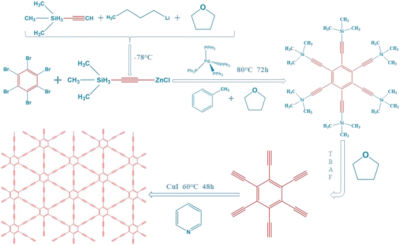
First, 4.3 mL ethynyltrimethylsilane was dissolved in a three-neck flask containing 35 mL tetrahydrofuran and protected with N2. At −78 °C, 12 mL of n-butyllithium solution dissolved in tetrahydrofuran was added to the above solution slowly dropwise near the liquid surface, and stirred for 30 minutes. Then, 20 mL of anhydrous zinc chloride solution dissolved in tetrahydrofuran was added dropwise to the reaction with continuous stirring. After 30 minutes, it rose to room temperature, and 1.104 g hexabromobenzene, 500 mg tetrakis(triphenylphosphine)palladium(0) and 25 mL toluene were added. The reaction was continued under an atmosphere of nitrogen at 80 °C for 3 days. After the reaction, 20 mL of 1 mol L−1 HCl was added to the system, which was separated by extraction with ethyl acetate. The bottom solution was removed and the top solution was washed. Then, it was dried with anhydrous sodium sulfate, concentrated to dry, separated and purified by eluent column chromatography with a mixture of n-hexane and dichloromethane (volume ratio 4![[thin space (1/6-em)]](https://www.rsc.org/images/entities/char_2009.gif) :
:![[thin space (1/6-em)]](https://www.rsc.org/images/entities/char_2009.gif) 1) to obtain a pale yellow solid hexakis[(trimethylsilyl)ethynyl]benzene. The obtained intermediates were dissolved in 20 mL tetrahydrofuran, and 0.4 mL tetrabutylammonium fluoride solution was added under the protection of N2. After continuous stirring for 10 minutes at 8 °C, extraction was carried out using ethyl acetate, washing with saturated brine, drying with anhydrous sodium sulfate, and concentrating and drying to obtain a black solid hexylenyl benzene. The black solid was dissolved with 25 mL of pyridine, and added dropwise under N2 protection to a three-neck flask containing 50 mL of pyridine and 500 mg of CuI within 24 h. This process was performed at 60 °C. After drip-adding, the 2-days reaction was followed by concentration to dry to obtain CuI–GDY.17,25 To obtain pure GDY, CuI–GDY was washed with ammonia to remove CuI acting as a “crystal nucleus” until the liquid was colorless. After oven drying, pure GDY was obtained (Fig. 1).
1) to obtain a pale yellow solid hexakis[(trimethylsilyl)ethynyl]benzene. The obtained intermediates were dissolved in 20 mL tetrahydrofuran, and 0.4 mL tetrabutylammonium fluoride solution was added under the protection of N2. After continuous stirring for 10 minutes at 8 °C, extraction was carried out using ethyl acetate, washing with saturated brine, drying with anhydrous sodium sulfate, and concentrating and drying to obtain a black solid hexylenyl benzene. The black solid was dissolved with 25 mL of pyridine, and added dropwise under N2 protection to a three-neck flask containing 50 mL of pyridine and 500 mg of CuI within 24 h. This process was performed at 60 °C. After drip-adding, the 2-days reaction was followed by concentration to dry to obtain CuI–GDY.17,25 To obtain pure GDY, CuI–GDY was washed with ammonia to remove CuI acting as a “crystal nucleus” until the liquid was colorless. After oven drying, pure GDY was obtained (Fig. 1).
2.2. Preparation of NiMn(LDHs) and composite catalyst
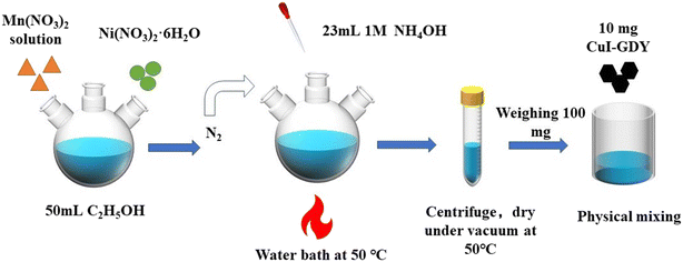
First, 3 mmol of Ni(NO3)2·6H2O and 1.5 mmol of Mn(NO3)2 were weighed into a three-mouth flask containing 100 mL of absolute ethanol, and stirred to disperse evenly. Under the atmosphere of N2 and the water bath kept at 50 °C, 23 mL of ammonia (1 mol L−1) was measured and added to the above solution dropwise, and the product was continuously stirred for one hour. The product was left to stand, washed with deionized water and ethanol, and then transferred to a vacuum-pressure desiccator for drying at 50 °C overnight.A mass of 10 mg of GDY was weighed and added to a beaker containing 30 mL of anhydrous ethanol, and the mixture was uniformly dispersed by ultrasound. Then, 100 mg of NiMn(LDHs) was added to the above solution. The mixture was stirred for 1 hour for even dispersion, then steamed at 70 °C in a water bath until the solution was thick. Finally, the sample was transferred to a vacuum oven at 50 °C to dry. The mixed catalyst NiMn(LDHs)-10 was obtained, and other ratios of mixed catalyst NiMn(LDHs)-x (x = 5, 15, 20, and 25) were prepared using the same experimental procedure, with the only difference being the amount of CuI–GDY (Fig. 2).
2.3. Hydrogen production experiment
A photocatalytic hydrogen production experiment was carried out in a 65 mL glass bottle. A mass of 10 mg of catalyst powder and 10 mg of eosin Y water solution were weighed and added into 30 mL of aqueous triethanolamine (TEOA) solution (volume fraction: 15%). The mixture was sonicated to obtain an even dispersion, and N2 was infused for three minutes to remove air from the bottle. The multi-channel photocatalytic reaction system with 5 W of white light was used to simulate the sunlight. For each time that 0.5 mL of gas was extracted from the bottle, the hydrogen content was detected by Tianmei GC7900 gas chromatography (TCD, 13X column, N2 as carrier), and the hydrogen production was analyzed by the external standard method.2.4. Instruments and medicines
The diffraction patterns of GDY, CuI–GDY, NiMn(LDHs) and NiMn(LDHs)/CuI–GDY were analyzed by X-ray diffractometer (XRD, Rigaku RINT-2000), with the test range and test speed set to 10–80° and 10° min−1. The microscopic morphologies of GDY, CuI–GDY, NiMn(LDHs) and NiMn(LDHs)/CuI–GDY were studied using a scanning electron microscope (SEM, Zeiss Evo 10) and transmission electron microscope (TEM, Tecnai, G2-TF30). An UV-2550 (Shimadzu) spectrometer equipped with an integrating sphere was used to explore the visible light absorption of the samples between 250–800 nm. The photoluminescence spectral data of the material were recorded on the FLUOROMAX-4 spectrometer. The platinum electrode was used as the counter electrode, the calomel electrode was the reference electrode, and the sample was the working electrode for photoelectrochemical testing on the VersaStat4-400 electrochemical workstation. A 0.2 M Na2SO4 solution was used as the electrolyte, and 300 W xenon lamp was used as the light source (λ ≥ 420 nm cut-off filter). All drugs were analytically pure.3. Results and discussion
3.1. XRD analysis
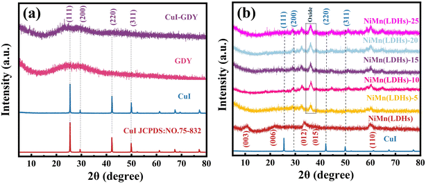
The crystallinity and crystal structure of CuI–GDY, GDY, CuI, NiMn(LDHs) and composite materials were analyzed by XRD. In Fig. 3(a), the peaks at 25.5°, 29.5°, 42.2° and 50.0° are attributed to the crystal faces (111), (200), (220) and (311) of CuI (PDF#75-832), respectively.38 These four facets can be seen in CuI–GDY. Due to wear in the synthesis process, the peak type of CuI is reduced. However, compared with pure CuI, the peak type of CuI can still be seen. In Fig. 3(b), the resulting products of NiMn(LDHs) exhibit a series of crystal face (003), (006), (012) and (015) reflection peaks at 11.3°, 22.7°, 33.4°, and 34.4°, respectively, which are typical diffraction patterns of LDHs, indicating that LDHs were successfully prepared.21 However, crystalline Mn3O4 appears in the composite due to partial oxidation, and the peak of CuI becomes obvious after the content of CuI–GDY increases. The success of the composite materials is illustrated.3.2. Infrared and Raman analysis
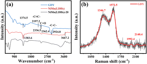
Functional groups of GDY, NiMn(LDHs) and NiMn(LDHs)-20 were identified by infrared spectroscopy. As depicted in Fig. 4(a), the tensile vibration of the acetylene bond of GDY results in a peak of 2197.2 cm−1,39 and stretching peaks of the aromatic ring skeleton appeared in the range of 1400–1600 cm−1. The energy bands at 2336.5 and 2362.4 cm−1 are caused by the C![[double bond, length as m-dash]](https://www.rsc.org/images/entities/char_e001.gif) O bond stretching vibrational mode of CO2, and the energy band at 1374.5 cm−1 is caused by the stretching vibration of the C–C/C–O bond.40,41 The stretching vibration of the H–O bond in NiMn(LDHs) gives rise to the energy band at 3667.2 cm−1, which is still very obvious in the composite catalyst. The tensile vibration of the N–O bond of NiMn(LDHs) results in a peak at 1383.6 cm−1. Fig. 4(b) shows the Raman spectra of GDY. The characteristic peak at 1346.7 cm−1 corresponds to the G band of sp2 carbon, which shows the interlayer stacking mode of carbon atoms in the sample. The characteristic peak at 1572.5 cm−1 may originate from the D band of the sp2 carbon.42 The vibration of the conjugated diyne chain (–C
O bond stretching vibrational mode of CO2, and the energy band at 1374.5 cm−1 is caused by the stretching vibration of the C–C/C–O bond.40,41 The stretching vibration of the H–O bond in NiMn(LDHs) gives rise to the energy band at 3667.2 cm−1, which is still very obvious in the composite catalyst. The tensile vibration of the N–O bond of NiMn(LDHs) results in a peak at 1383.6 cm−1. Fig. 4(b) shows the Raman spectra of GDY. The characteristic peak at 1346.7 cm−1 corresponds to the G band of sp2 carbon, which shows the interlayer stacking mode of carbon atoms in the sample. The characteristic peak at 1572.5 cm−1 may originate from the D band of the sp2 carbon.42 The vibration of the conjugated diyne chain (–C![[triple bond, length as m-dash]](https://www.rsc.org/images/entities/char_e002.gif) C–C
C–C![[triple bond, length as m-dash]](https://www.rsc.org/images/entities/char_e002.gif) C–) gives rise to the peaks at 1992.4 and 2140.4 cm−1.
C–) gives rise to the peaks at 1992.4 and 2140.4 cm−1.
3.3. XPS analysis
To further prove the successful compounding of CuI–GDY and NiMn(LDHs), XPS analysis was separately carried out on GDY, CuI–GDY, NiMn(LDHs) and NiMn(LDHs)-20. The results are shown in Fig. 5(a), indicating that only NiMn(LDHs) and composite catalysts have both Ni and Mn elements. The composition and valence state of CuI–GDY were clarified. Fig. 5(b) shows the XPS spectrum of C 1s, fitting four peaks at 284.50, 284.88, 286.05 and 288.68 eV, representing the C–C(sp2), C–C(sp), C–O and C![[double bond, length as m-dash]](https://www.rsc.org/images/entities/char_e001.gif) O bonds, respectively.43 The peak area of sp is twice that of sp2. Compared with pure GDY, all four peaks of C 1s in the composite catalyst are shifted to the high field, indicating that C loses electrons. Fig. 5(c) and (d) show spectrograms of Cu 2p at 933.00 and 952.70 eV, which correspond to Cu 2p3/2 and Cu 2p1/2, respectively.44 Furthermore, the peaks at 619.47 and 631.15 eV were attributed to I 3d5/2 and I 3d3/2, respectively.45 It can be seen that both Cu 2p and I 3d move to the high field. Fig. 5(e) is the spectrum of Ni 2p in NiMn(LDHs), corresponding to 856.18, 861.76, 874.06 and 880.03 eV. Ni moves to the low field after catalyst recombination, which indicates that Ni gets electrons. Fig. 5(f) is the spectrum of Mn 2p in NiMn(LDHs). The peaks at 643.70 and 656.17 eV correspond to Mn 2p3/2 and Mn 2p1/2, respectively. It can be seen that there is a small amount of oxidation state of Mn (Mn3+).32 Compared with the binding energy of the single catalyst, the composite catalyst shifts to different degrees, which proves the electron transfer between CuI, GDY and NiMn(LDHs).
O bonds, respectively.43 The peak area of sp is twice that of sp2. Compared with pure GDY, all four peaks of C 1s in the composite catalyst are shifted to the high field, indicating that C loses electrons. Fig. 5(c) and (d) show spectrograms of Cu 2p at 933.00 and 952.70 eV, which correspond to Cu 2p3/2 and Cu 2p1/2, respectively.44 Furthermore, the peaks at 619.47 and 631.15 eV were attributed to I 3d5/2 and I 3d3/2, respectively.45 It can be seen that both Cu 2p and I 3d move to the high field. Fig. 5(e) is the spectrum of Ni 2p in NiMn(LDHs), corresponding to 856.18, 861.76, 874.06 and 880.03 eV. Ni moves to the low field after catalyst recombination, which indicates that Ni gets electrons. Fig. 5(f) is the spectrum of Mn 2p in NiMn(LDHs). The peaks at 643.70 and 656.17 eV correspond to Mn 2p3/2 and Mn 2p1/2, respectively. It can be seen that there is a small amount of oxidation state of Mn (Mn3+).32 Compared with the binding energy of the single catalyst, the composite catalyst shifts to different degrees, which proves the electron transfer between CuI, GDY and NiMn(LDHs).
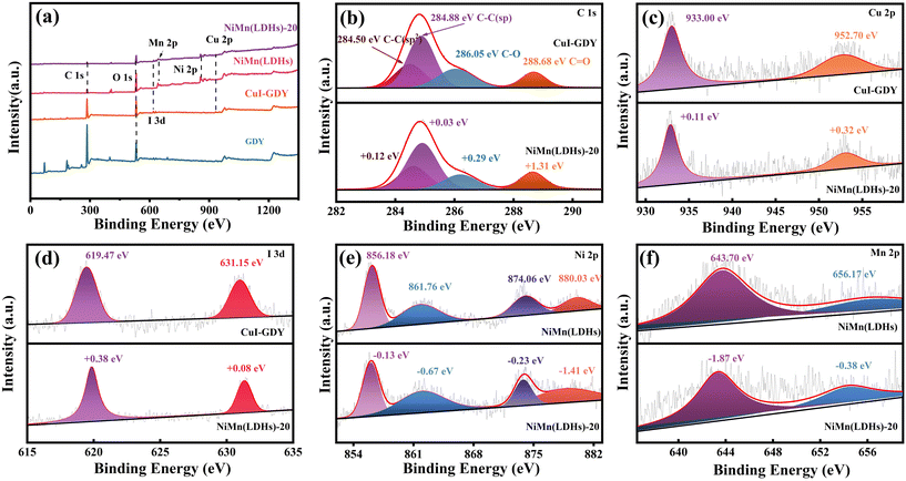 | ||
| Fig. 5 XPS spectra of GDY, CuI–GDY, NiMn(LDHs), NiMn(LDHs)-20 (a), and survey spectra and high-resolution spectra of C 1s (b), Cu 2p (c), I 3d (d), Ni 2p (e), and Mn 2p (f). | ||
3.4. SEM and TEM analysis
The microstructures and morphologies of CuI, GDY, CuI–GDY, NiMn(LDHs) and NiMn(LDHs)-20 were obtained by SEM. Fig. 6(a) shows the petal-like sheets stacked together in NiMn(LDHs). With a large specific surface area and rough surface, it is easy to load substances. Fig. 6(b and c) show the stone-like CuI and the layered stacked GDY. CuI is like stone and GDY is like cement, and the two are mixed together. This combination forms CuI–GDY, and its morphology can be seen in Fig. 6(d). In Fig. 6(e), two different aggregated states of CuI and NiMn(LDHs) are clearly visible. CuI–GDY is loaded on the rough surface of NiMn(LDHs), indicating the successful preparation of NiMn(LDHs)-20. Fig. 6(f) shows the TEM of the composite catalyst NiMn(LDHs)-20. The thick and poor light transmittance CuI particles, CuI–GDY generated by the combination of CuI and villous GDY with border zone, and sheet-like NiMn(LDHs) can be observed from the TEM. Fig. 6(g and h) is the HRTEM diagram of the composite catalyst NiMn(LDHs)-20. We can see the lattice fringes (0.217 nm) belonging to the crystal plane of CuI (220), and (0.259 nm) belonging to the crystal plane of NiMn(LDHs) (012). Fig. 6(j) is the EDX detection result. The EDX results show that it contains Ni, Mn, C, O, I and Cu elements, which strongly proves the successful preparation of NiMn(LDHs)-20.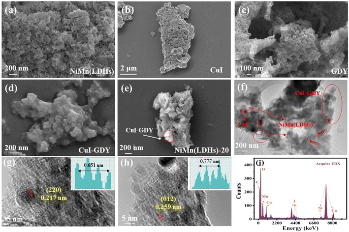 | ||
| Fig. 6 (a–e) SEM of NiMn(LDHs), CuI, GDY, CuI–GDY, and NiMn(LDHs)-20. (f) TEM of NiMn(LDHs)-20, (g and h) HRTEM of NiMn(LDHS)-20, (j) and EDX of NiMn(LDHs)-20. | ||
3.5. UV-vis DRS analysis
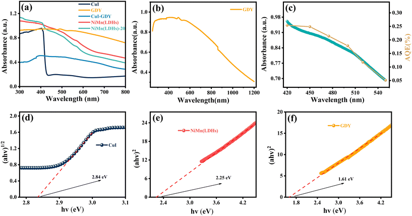
In general, the photocatalyst activity is positively correlated with the light absorption capacity of the photocatalyst.46–48 The light absorption properties of the samples were tested using UV-vis diffuse reflectance spectroscopy, and the results are shown in Fig. 7(a). GDY has good light absorption in the visible range. CuI has an obvious absorption band at 420 nm, which is still visible in NiMn(LDHs)-20, indicating the success of the composite materials. Fig. 7(b) shows the light absorption intensity of GDY. As shown in Fig. 7(c), we then measured the apparent quantum efficiency (AQE) of the composite catalyst NiMn(LDHs)-20 (10 mg catalyst, 10 mg EY, 30 mL TEOA). The AQE was found to match the UV absorption curve of NiMn(LDHs)-20 well, which indicates that the catalyst has strong stability. Optical absorption is typically used to estimate the band gap of the prepared nanocatalysts.49,50 Preliminary calculations for the band gap width of the catalyst can be made using the formula: αhν = A(hν − Eg)m/2, where α is the absorbance index, h is Planck's constant, ν is the frequency, Eg is the semiconductor forbidden band width, A is a constant, and the value of m is related to whether the material has direct band gap (m = 1) or indirect band gap (m = 4).51 As shown in Fig. 7(d–f), the Eg of CuI, NiMn(LDHs) and GDY are 2.84, 2.25 and 1.61 eV, respectively.3.6. The PL and TRPL spectra
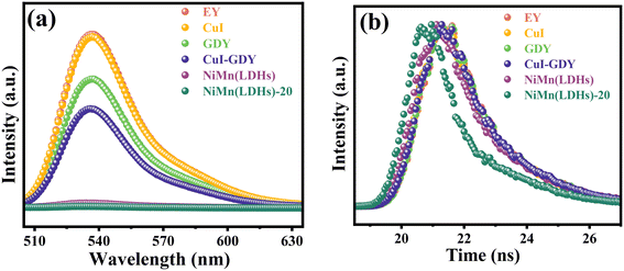
The photoluminescence properties of the catalysts were measured in EY solution. Simple EY and CuI–GDY produce strong fluorescence under light excitation, as shown in Fig. 9(a). This means that more excited electrons transformed by radiation decay return to the ground state.52 As a result, the electron–hole recombination occurs faster, which counts against the hydrogen precipitation reaction. In all samples, the composite catalyst NiMn(LDHs)-20 has the lowest emission intensity. This is because the layered structure of NiMn(LDHs) has a large specific surface area, thus facilitating the anchoring of CuI–GDY and speeding up the transfer of photogenerated electrons. More photogenerated electrons participate in the hydrogen evolution reaction and improve the utilization of photogenerated electrons. This corresponds to the catalytic activity of the samples. The peak intensities of EY, GDY, CuI–GDY, NiMn(LDHs), NiMn(LDHs)–CuI and NiMn(LDHs)-20 decrease successively, so the hydrogen production efficiency increases successively. To further research the interaction relationship between dye and catalyst, the lifetime of the samples was detected using fluorescence transients, and the results are shown in Table 1. The average lifetime, in particular, refers to the time it takes electrons to transition from the excited to the ground state. However, when CuI–GDY and NiMn(LDHs) are compounded, their average lifetime decreases significantly. This suggests that the electron transfer rate is accelerated, allowing more photogenerated electrons to participate in the hydrogen precipitation reaction. This increases the hydrogen production activity owing to the possible shape of the S-scheme heterojunction between the three.53 A built-in electric field is formed inside the formed S-scheme heterojunction catalyst, providing an electron transfer channel. The Coulomb forces and energy band edge bending act to induce more useful electrons to participate in the reduction reaction.54–56 To further demonstrate the formation of S-scheme heterojunctions between the composite catalysts, we calculated the electron transfer rates of the samples. The average lifetime of the samples measured by steady-state fluorescence was used to calculate the electron transfer rate in the samples using the following equation:| ket = τave(sample)−1 − τave(EY)−1 |
| Samples | τ 1 [ns] | τ 2 [ns] | τ ave [ns] | k et [109 s−1] |
|---|---|---|---|---|
| EY | 1.202 (100.00%) | — | 1.202 | 0 |
| CuI | 0.991 (70.14%) | 1.644 (29.86%) | 1.125 | 0.057 |
| GDY | 1.082 (87.35%) | 2.037 (12.65%) | 1.150 | 0.039 |
| NiMn(LDHs) | 0.875 (52.31%) | 1.673 (47.69%) | 1.132 | 0.051 |
| CuI–GDY | 0.993 (66.82%) | 1.683 (33.18%) | 1.149 | 0.038 |
| NiMn(LDHs)-20 | 1.457 (42.30%) | 0.083 (57.70%) | 0.139 | 6.362 |
The calculation results are shown in Table 1. We found that the electron transfer rate of the composite catalyst NiMn(LDHs)-20 was considerably faster compared with that of the single catalyst, suggesting the formation of the S-scheme heterojunctions between catalysts.53
3.7. Photocatalytic hydrogen evolution activity
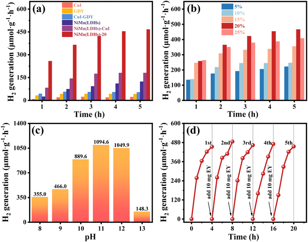
The photocatalytic hydrogen production performance of the samples was investigated in a closed reaction system under visible light irradiation using a volume fraction of 15% and pH = 9 TEOA as a sacrificial reagent. As shown in Fig. 8(a), CuI, GDY, CuI–GDY, NiMn(LDHs)–CuI, pure NiMn(LDHs) and composite samples were used as catalysts to study the hydrogen production rate of the system. The hydrogen production rates of pure GDY, CuI, and NiMn(LDHs) are low. Furthermore, even the binary catalysts CuI–GDY and NiMn(LDHs)–CuI without GDY have average hydrogen production activity. When GDY is introduced to NiMn(LDHs), the hydrogen production rate is significantly increased. As shown in Fig. 8(b), when the content of CuI–GDY reaches 20%, the hydrogen evolution activity of the composite catalyst is at its best. However, when the content of CuI–GDY is greater than 20%, the hydrogen evolution activity of the composite catalyst decreases significantly. This result may arise from the accumulation of excessive CuI–GDY, which prevents more light from reaching NiMn(LDHs).Simultaneously, to study the activity of the composite catalyst in sacrificial reagents with different pH, the control test was set up to change only the pH of the sacrificial reagent to obtain the hydrogen production at each pH for 5 hours, as shown in Fig. 8(c). NiMn(LDHs)-20 has the best hydrogen evolution activity at pH = 11. The hydrogen production in 5 hours is 1094.6 μmol g−1 h−1, which is about 2.3 times of that in Fig. 8(a). When pH = 12, the hydrogen production starts to decrease gradually. When it reaches pH = 13, the hydrogen production drops sharply. This is because the over alkaline environment will cause the oxidation degradation of TEOA to accelerate. On the other hand, the driving force for hydrogen production from water cleavage depends on the concentration of H+ in the sacrificed reagent. Thus, there is a lower driving force for hydrogen production with increasing alkaline environment. However, this does not mean that a lower pH is better. A weak base environment that is close to neutral will protonate the sacrificial reagent so that it will provide fewer effective electrons. Thus, the hydrogen production activity will decrease, as shown in Fig. 8(c), when pH = 8. The results showed that to ensure the high activity of the catalyst, a sacrificial reagent with an appropriate pH value should be selected.
The catalyst should not be judged by the amount of hydrogen produced alone. The stability of the catalyst should also be taken into account. Therefore, we used 10 mg of EY in TEOA with pH = 9 to study the cyclic stability of the catalyst. As shown in Fig. 8(d), five cycles were performed for a total of 20 hours. TEOA was not replaced during the cycle. However, 10 mg of EY was added in each cycle. Using N2 to drain the gas in the bottle, there is only a slight decrease in the hydrogen production capacity of the catalyst at the end of each cycle. Therefore, the catalyst has strong cycle stability.
3.8. The electrochemical characterization test
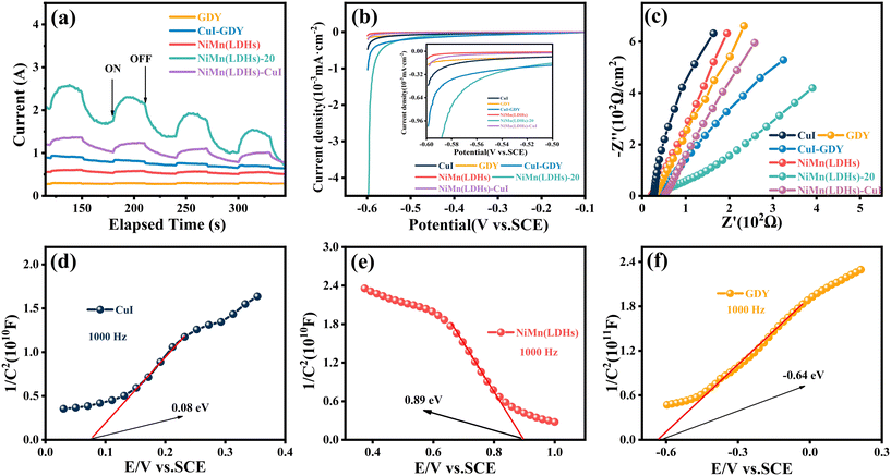
Too often, the photocurrent response is an effective method to evaluate the capability of photogenerated carrier separation.57 The photocurrent densities of different samples were tested under the same experimental conditions, and the test results are shown in Fig. 10(a). The pure GDY photocurrent density is the lowest. However, the photocurrent density of the composite NiMn(LDHs)–CuI is relatively higher because CuI and NiMn(LDHs) construct an S-scheme heterojunction to accelerate the transfer of photogenerated carriers.58 Similarly, the composite catalyst showed the strongest photocurrent density compared with pure GDY and NiMn(LDHs). This indicates that the number of photogenerated carriers involved in recombination decreases, while the number of photogenerated carriers involved in hydrogen evolution reaction increases. This represents an increase in the utilization rate of generated photogenerated electrons, thus favoring hydrogen production.The linear sweep voltammetry (LSV) results of the sample are shown in Fig. 10(b). NiMn(LDHs)-20 has the smallest current intensity in the same potential region, indicating that it has the smallest energy barrier and requires the least energy for the hydrogen evolution reaction. So, in the same potential region, the lower the current intensity, the more favorable the hydrogen precipitation reaction.59Fig. 10(c) shows the electrochemical impedance spectroscopy (EIS) results of the sample. The electric arc radius can be used to determine the magnitude of the resistance during charge transfer at the interface between the working electrode and the electrolyte.60–62 Furthermore, the composite catalyst NiMn(LDHs)-20 has the smallest electric arc radius, implying that charge transfer resistance is minimal. This indicates that the impedance of the composite catalyst composed of NiMn(LDHs) and CuI–GDY combined is greatly reduced. The greatly reduced impedance facilitates the transfer of photogenerated carriers and reduces the transfer time of photogenerated carriers, thus reducing the complexation of electron–hole pairs. This is favorable for the hydrogen evolution reaction.
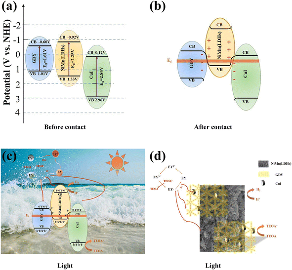
The Mott–Schottky of CuI, NiMn(LDHs) and GDY were tested at 1000 Hz. It can be concluded as shown in Fig. 10(d–f) that the CuI, NiMn(LDHs) and GDY flat band potential (Efb) are 0.08, 0.89 and −0.64 eV, respectively. It is known from the literature that CuI and GDY are n-type semiconductors. Based on the experimentally measured data, it is known that NiMn(LDHs) is a p-type semiconductor. In general, the conduction band potential (ECB) of an n-type semiconductor is more negative (−0.1 or −0.2 eV) than its flat band potential, while the valence band potential (EVB) of a p-type semiconductor is more positive (0.1 or 0.2 eV),63 according to the formula ENHE = ESCE + 0.24, where ENHE is the standard normal hydrogen electrode and ESCE is the saturated calomel electrode potential. Combined with the band gap measured in UV-vis, the conduction band (CB) and valence band (VB) information of the three catalysts can be obtained as shown in Fig. 11(a).
3.9. Proposed reaction mechanism
The possible hydrogen production mechanism of the CuI–GDY/NiMn(LDHs) composite catalyst was proposed based on the above contents. As shown in Fig. 11(a–d), first of all, when the catalyst contacts, the electrons in the NiMn(LDHs) valence band are transferred to GDY and CuI until the Fermi levels of the three are equal. At this time, NiMn(LDHs) becomes positively charged due to losing electrons, while GDY and CuI become negatively charged due to gaining electrons. Then EY is excited by visible light into a singly excited EY1* state, and then converted to the more stable triple excited state EY3* by intersystem transition (ISC). TEOA provides electrons to reduce EY3* to a strongly reduced EY−˙. Following that, EY−˙ is transferred to the surface of the catalyst to participate in the hydrogen evolution reaction, while it is oxidized back to the ground state. When the composite catalyst is illuminated by light, the electrons on CB of GDY and CuI are closer to the hole on VB of NiMn(LDHs), so the electrons on CB of GDY and CuI are more inclined to flow to the hole on VB of NiMn(LDHs), rather than combine with the hole itself. Thus, the electron–hole pair recombination of the semiconductor itself is reduced, and the hydrogen evolution ability is improved macroscopically.4. Conclusion
In this paper, CuI–GDY was synthesized by an organic method, and CuI–GDY/NiMn(LDHs) nanocomposites were obtained by simple physical mixing. Under the action of CuI–GDY, the charge separation and transfer rate of NiMn(LDHs) in the mixed catalyst are significantly increased, and the recombination rate of the electron–hole pair is significantly inhibited. Under the condition of light, the hydrogen production rate reaches 1094.6 μmol g−1 h−1, which is about 11.24, 8.80, 20.99, 3.78 and 2.58 times higher when compared to pure GDY, CuI–GDY, CuI, NiMn(LDHs) and NiMn(LDHs)–CuI. The double S-scheme heterojunctions constructed between the composite catalysts accelerate the electron transfer rate, resulting in more photogenerated electrons participating in the reduction of protons (H+) at the active site. The good stability of GDY is brought to the composite catalyst after compounding. This causes the hole–electron pair compounding rate of the composite catalyst to decrease, thus enabling the composite catalysts to maintain good hydrogen precipitation activity even after 20 hours of cycling, and further improves the hydrogen precipitation activity. This certainly provides a new idea for the application of CuI–GDY.Author contributions
This experiment was designed by Zhenkun Liu. Zhenkun Liu performed the experiments; Zhiliang Jin provided reagents, materials, and analytical tools; Zhenkun Liu wrote the article.Conflicts of interest
The authors declare no competing financial interest.Acknowledgements
This work was financially supported by the Innovative Team for Transforming Waste Cooking Oil into Clean Energy and High Value-Added Chemicals, China and Ningxia Low-Grade Resource High Value Utilization and Environmental Chemical Integration Technology Innovation Team Project.References
- T. Yan, X. Zhang, H. Liu and Z. Jin, CeO2 particles anchored to Ni2P nanoplate for efficient photocatalytic hydrogen evolution, Chin. J. Struct. Chem., 2022, 41, 2201047–2201053 CAS
.
- J. Zhang, C. Cheng, F. S. Xing, C. Chen and C. Huang, 0D β-Ni(OH)2 nanoparticles/1D Mn0.3Cd0.7S nanorods with rich S vacancies for improved photocatalytic H2 production, Chem. Eng. J., 2021, 414, 129157 CrossRef CAS
.
- Y. Liu, X. Hao, H. Hu and Z. Jin, High efficiency electron transfer realized over NiS2/MoSe2 S-scheme heterojunction in photocatalytic hydrogen evolution, Acta Phys.-Chim. Sin., 2021, 37(6), 2008030 Search PubMed
.
- Z. Jin, Y. Li and X. Hao, Ni, Co-based selenide anchored g-C3N4 for boosting photocatalytic hydrogen evolution, Acta Phys.-Chim. Sin., 2021, 37(10), 1912033 Search PubMed
.
- S. Liu, K. Wang, M. Yang and Z. Jin, Rationally designed Mn0.2Cd0.8S@CoAl LDH S-scheme heterojunction for efficient photocatalytic hydrogen production, Acta Phys.-Chim. Sin., 2022, 38(7), 2109023 Search PubMed
.
- H. Li, H. Gong and Z. Jin, In2O3-modified Three-dimensional nanoflower MoSx form S-scheme heterojunction for efficient hydrogen production, Acta Phys.-Chim. Sin., 2022, 38, 2201037 Search PubMed
.
- G. Wang, Y. Quan, K. Yang and Z. Jin, EDA-assisted synthesis of multifunctional snowflake-Cu2S/CdZnS S-Scheme heterjunction for improved the photocatalytic hydrogen evolution, J. Mater. Sci. Technol., 2022, 121, 28–39 CrossRef
.
- Z. Jiang, Q. Chen, Q. Zheng, R. Shen, P. Zhang and X. Li, Constructing 1D/2D schottky-based heterojunctions between Mn0.2Cd0.8S Nanorods and Ti3C2 nanosheets for boosted photocatalytic H2 evolution, Acta Phys.-Chim. Sin., 2021, 37(6), 2009063 Search PubMed
.
- Z. Fan, X. Guo, Z. Jin, X. Li and Y. Li, Bridging effect of S-C bond for boosting electron transfer over cubic hollow CoS/g-C3N4 heterojunction toward photocatalytic hydrogen production, Langmuir, 2022, 38(10), 3244–3256 CrossRef CAS PubMed
.
- F. Yang, X. Chua, J. Sun, Y. Zhang, Z. Li, H. Liu, L. Bai, Q. Yang and L. Jing, Efficient singlet oxygen generation by excitonic energy transfer on ultrathin g-C3N4 for selective photocatalytic oxidation of methyl-phenyl-sulfide with O2, Chin. Chem. Lett., 2020, 31, 2784–2788 CrossRef CAS
.
- R. Yan, A. Zada, L. Sun, Z. Li, Z. Mu, S. Chen, F. Yang, J. Sun, L. Bai, Y. Qu and L. Jing, Comparative study of metal oxides and phosphate modification with different mechanisms over g-C3N4 for visible-light photocatalytic degradation of Metribuzin, Rare Met., 2022, 41, 155–165 CrossRef CAS
.
- Y. Wang, Y. Qu, B. Qu, L. Bai, Y. Liu, Z. Yang, W. Zhang, L. Jing and H. Fu, Construction of Six-Oxygen-Coordinated Single Ni Sites on g-C3N4 with Boron-Oxo Species for Photocatalytic Water-Activation-Induced CO2 Reduction, Adv. Mater., 2021, 33, 2105482 CrossRef CAS PubMed
.
- X. Li, K. Pan, Y. Qu and G. Wang, One dimension carbon self-doping g-C3N4 nanotubes: synthesis and application in dye-sensitized solar cells, Nano Res., 2018, 11(3), 1322–1330 CrossRef CAS
.
- Y. Cao, H. Gou, P. Zhu and Z. Jin, Ingenious design of CoAl-LDH p-n heterojunction based on CuI as holes receptor for photocatalytic hydrogen evolution, Chin. J. Struct. Chem., 2022, 41, 2206079–2206085 CAS
.
- J. Zou, G. Liao, J. Jiang, Z. Xiong, S. Bai, H. Wang, P. Wu and P. Zhang, In-situ Construction of Sulfur-doped g-C3N4/defective g-C3N4 Isotype Step-scheme Heterojunction
for Boosting Photocatalytic H2 Evolution, Chin. J. Struct. Chem., 2022, 41, 2201025–2201033 CAS
.
- Z. Jin, T. Li, L. Zhang, X. Wang, G. Wang and X. Hao, Construction of a tandem S-scheme GDY/CuI/CdS-R heterostructure based on morphology-regulated graphdiyne (g-CnH2n-2) for enhanced photocatalytic hydrogen evolution, J. Mater. Chem. A, 2022, 10, 1976–1991 RSC
.
- Z. Jin and H. Gong, A New Allotrope of Carbon—Graphdiyne (g-CnH2n−2) Boosting with Mn0.2Cd0.8S form S-Scheme Heterojunction for Efficient Photocatalytic Hydrogen Evolution, Adv. Mater. Interfaces, 2021, 8, 2100630 CrossRef CAS
.
- D. Ren, R. Shen, Z. Jiang, X. Lu and X. Li, Highly efficient visible-light photocatalytic H2 evolution over 2D-2D CdS/Cu7S4 layered heterojunctions, Chin. J. Catal., 2020, 41, 31–40 CrossRef CAS
.
- R. Shen, Y. Ding, S. Li, P. Zhang, Q. Xiang, Y. Hau and X. Li, Constructing low-cost Ni3C/twin-crystal Zn0.5Cd0.5S heterojunction/homojunction nanohybrids for efficient photocatalytic H2 evolution, Chinese, Chin. J. Catal., 2021, 42, 25–36 CrossRef CAS
.
- Y. Liu, M. Lu, T.-P. Perng and L.-J. Chen, Plasmonic enhancement of hydrogen production by water splitting with CdS nanowires protected by metallic TiN overlayers as highly efficient photocatalysts, Nano Energy, 2021, 89, 106407 CrossRef CAS
.
- J. Qin, X. Hua, X. Li, Z. Yin, B. Liu and K.-H. Lam, 0D/2D AgInS2/MXene Z-scheme heterojunction nanosheets for improved ammonia photosynthesis of N2, Nano Energy, 2019, 61, 27–35 CrossRef CAS
.
- S. Wageh, A. A. Al-Ghamdi, R. Jafer, X. Li and P. Zhang, A new heterojunction in photocatalysis: S-scheme heterojunction, Chin. J. Catal., 2021, 42, 667–669 CrossRef CAS
.
- J. Wei, Y. Chen, H. Zhang, Z. Zhuang and Y. Yan, Hierarchically porous S-scheme CdS/UiO-66 photocatalyst for efficient 4-nitroaniline reduction, Chin. J. Catal., 2021, 42, 78–86 CrossRef CAS
.
- J. Peng, J. Shen, X. Yu, H. Tang, Zulfiqar and Q. Liu, Construction of LSPR-enhanced 0D/2D CdS/MoO3-x S-scheme heterojunctions for visible-light-driven photocatalytic H2 evolution, Chin. J. Catal., 2021, 42, 87–96 CrossRef CAS
.
- Y. Fang, Y. Liu, L. Qi, Y. Xue and Y. Li, 2D graphdiyne: an emerging carbon material, Chem. Soc. Rev., 2022, 51, 2681–2709 RSC
.
- G. Li, Y. Li, H. Liu, Y. Guo, Y. Li and D. Zhu, Architecture of graphdiyne nanoscale films, Chem. Commun., 2010, 46, 3256–3258 RSC
.
- Z. Zuo, F. He, F. Wang, L. Li and Y. Li, Spontaneously Splitting Copper Nanowires into Quantum Dots on Graphdiyne for Suppressing Lithium Dendrites, Adv. Mater., 2020, 32, 2004379 CrossRef CAS PubMed
.
- X. Qian, Z. Ning, Y. Li, H. Liu, C. Ouyang, Q. Chen and Y. Li, Construction of graphdiyne nanowires with high-conductivity and mobility, Dalton Trans., 2012, 41, 730–733 RSC
.
- Y. Zhao, J. Wan, H. Yao, L. Zhang, K. Lin, L. Wang, N. Yang, D. Liu, L. Song, J. Zhu, G. Lin, L. Liu, H. Zhao, Y. Li and D. Wang, Few-layer graphdiyne doped with sp-hybridized nitrogen atoms at acetylenic sites for oxygen reduction electrocatalysis, Nat. Chem., 2018, 10, 924–931 CrossRef CAS PubMed
.
- J. Yang, C. Yu, X. Fan, J. Qiu, J. Yang, C. Yu, X. Fan and J. Qiu, 3D Architecture Materials Made of NiCoAl-LDH Nanoplates Coupled with NiCo-Carbonate Hydroxide Nanowires Grown on Flexible Graphite Paper for Asymmetric Supercapacitors, Adv. Energy Mater., 2014, 4, 1400761 CrossRef
.
- J. Chen, X. Wang, J. Wang and P. S. Lee, Sulfidation of NiMn-Layered Double Hydroxides/Graphene Oxide Composites toward Supercapacitor Electrodes with Enhanced Performance, Adv. Energy Mater., 2016, 6, 1501745 CrossRef
.
- M. Li, P. Yuan, S. Guo, F. Liu and J. P. Cheng, Design and synthesis of Ni-Co and Ni-Mn layered double hydroxides hollow microspheres for supercapacitor, Int. J. Hydrogen Energy, 2017, 42, 28797–28806 CrossRef CAS
.
- Z. Fan, X. Zhang, Y. Li, X. Guo and Z. Jin, Construct 3D NiCo-LDH/Cu2O p-n heterojunction via electrostatic self-assembly for enhanced photocatalytic hydrogen evolution, J. Ind. Eng. Chem., 2022, 110, 491–502 CrossRef CAS
.
- Y. Wu, Y. Li, L. Zhang and Z. Jin, NiAl-LDH in situ derived Ni2P and ZnCdS nanoparticles ingeniously constructed S-scheme heterojunction for photocatalytic hydrogen production, ChemCatChem, 2022, 14, e202101656 CAS
.
- M. Yu, R. Liu, J. Liu, S. Li and Y. Ma, Polyhedral-Like NiMn-Layered Double Hydroxide/Porous Carbon as Electrode for Enhanced Electrochemical Performance Supercapacitors, Small, 2017, 13, 1702616 CrossRef PubMed
.
- Z. Jin, Y. Li and Q. Ma, CoAl LDH@Ni-MOF-74 S-Scheme Heterojunction for Efficient Hydrogen Evolution, Trans. Tianjin Univ., 2021, 27, 127–138 CrossRef CAS
.
- D. Li, X. Ma, P. Su, S. Yang, Z. Jiang, Y. Li and Z. Jin, Effect of phosphating on NiAl-LDH layered double hydroxide form S-scheme heterojunction for photocatalytic hydrogen evolution, Mol. Catal., 2021, 516, 111990 CrossRef CAS
.
- Y. Li, H. Yang, G. Wang, B. Ma and Z. Jin, Distinctive Improved Synthesis and Application Extensions Graphdiyne for Efficient Photocatalytic Hydrogen Evolution, ChemCatChem, 2020, 12, 1985–1995 CrossRef CAS
.
- Z. Jin, H. Li and J. Li, Efficient photocatalytic hydrogen evolution over graphdiyne boosted with a cobalt sulfide formed S-scheme heterojunctions, Chin. J. Catal., 2022, 42, 303–315 CrossRef
.
- Q. Xu, B. Zhua, B. Cheng, J. Yu, M. Zhou and W. Ho, Photocatalytic H2 Evolution on Graphdiyne/g-C3N4 Hybrid Nano-composites, Appl. Catal., B, 2019, 255, 117770 CrossRef CAS
.
- K. Yang, T. Liu, D. Xiang, Y. Li and Z. Jin, Graphdiyne (g-CnH2n-2) based Co3S4 anchoring and edge-covalently modification coupled with carbon-defects g-C3N4 for photocatalytic hydrogen production, Sep. Purif. Technol., 2022, 298, 121564 CrossRef CAS
.
- Y. Jia, L. Zhang, A. Du, G. Gao, J. Chen, X. Yan, C. L. Brown and X. Yao, Defect Graphene As a Trifunctional Catalyst for Electrochemical Reactions, Adv. Mater., 2016, 28, 9532–9538 CrossRef CAS PubMed
.
- A. C. Ferrari, J. C. Meyer, V. Scardaci, C. Casiraghi, M. Lazzeri, F. Mauri, S. Piscanec, D. Jiang, K. S. Novoselov, S. Roth and A. K. Geim, Raman Spectrum of Graphene and Graphene Layers, Phys. Rev. Lett., 2006, 97, 187401 CrossRef CAS PubMed
.
- Z. Jin, L. Zhang, G. Wang, Y. Li and Y. Wang, Graphdiyne Formed a Novel CuI-GD/g-C3N4 S-scheme Hetero-junction Composite for Efficient Photocatalytic Hydrogen Evolution, Sustain, Sustain. Energy Fuels, 2020, 4, 5088–5101 RSC
.
- N. Yamada, R. Ino and Y. Ninomiya, Truly Transparent p-Type γ-CuI Thin Films with High Hole Mobility, Chem. Mater., 2016, 28, 4971–4981 CrossRef CAS
.
- H. Gong, Y. Li, H. Li and Z. Jin, 2D CeO2 and partial phosphated 2D Ni-based metal-organic
framework formed S-scheme heterojunction for efficient photocatalytic hydrogen evolution, Langmuir, 2022, 38, 2117–2131 CrossRef CAS PubMed
.
- J. Li, M. Li, Y. Li, X. Guo and Z. Jin, Lotus-leaf-like Bi2O2CO3 nanosheet combined with Mo2S3 for higher photocatalytic hydrogen evolution, Sep. Purif. Technol., 2022, 288, 120588 CrossRef CAS
.
- R. Gao, H. He, J. Bai, L. Hao, R. Shen, P. Zhang, Y. Li and X. Li, Pyrene-benzothiadiazole-based Polymer/CdS 2D/2D Organic/Inorganic Hybrid S-scheme Heterojunction for Efficient Photocatalytic H2 Evolution, Chin. J. Struct. Chem., 2022, 41, 2206031–2206038 CAS
.
- L. Zhang, X. Hao, Y. Li and Z. Jin, Performance of WO3/g-C3N4 heterojunction composite boosting with NiS for photocatalytic hydrogen evolution, Appl. Surf. Sci., 2020, 499, 143862 CrossRef CAS
.
- B. Wang, S. He, W. Feng, L. Zhang, X. Huang, K. Wang, S. Zhang and P. Liu, Rational design and facile in situ coupling non-noble metal Cd nanoparticles and CdS nanorods for efficient visible-light-driven photocatalytic H2 evolution, Appl. Catal., B, 2018, 236, 233–239 CrossRef CAS
.
- Y. Wang, X. Hao, L. Zhang, Z. Jin and T. Zhao, Amorphous Co3S4 Nanoparticle-Modified Tubular g-C3N4 forms Step-scheme Heterojunctions for Photocatalytic Hydrogen Production, Catal. Sci. Technol., 2021, 11, 943–955 RSC
.
- J. Tian, Q. Liu, N. Cheng, A. M. Asiri and X. Sun, Self-Supported Cu3P Nanowire Arrays as an Integrated High-Performance Three-Dimensional Cathode for Generating Hydrogen from Water, Angew. Chem., 2014, 126, 9731–9735 CrossRef
.
- Q. Xu, L. Zhang, B. Cheng, J. Fan and J. Yu, S-Scheme Heterojunction Photocatalyst, Chem, 2020, 6, 1543–1559 CAS
.
- A. Meng, B. Cheng, H. Tan, J. Fan, C. Su and Y. Jiaguo, TiO2/polydopamine S-scheme heterojunction photocatalyst with enhanced CO2-reduction selectivity, Appl. Catal., B, 2021, 289, 120039 CrossRef CAS
.
- X. Han, B. Lu, X. Huang, C. Liu, S. Chen, J. Chen, Z. Zeng, S. Deng and J. Wang, Novel p- and n-type S-scheme heterojunction photocatalyst for boosted CO2 photoreduction activity, Appl. Catal., B, 2022, 316, 121587 CrossRef CAS
.
- L. Chen, X. Song, J. Ren and Z. Yuan, Precisely modifying Co2P/black TiO2 S-scheme heterojunction by in situ formed P and C dopants for enhanced photocatalytic H2 production, Appl. Catal., B, 2022, 315, 121546 CrossRef CAS
.
- L. Zhang, X. Hao, Q. Jian and Z. Jin, Ferrous oxalate dehydrate over CdS as Z-scheme photocatalytic hydrogen evolution, J. Solid State Chem., 2019, 274, 286–294 CrossRef CAS
.
- Z. Jin, X. Wang, X. Hao, G. Wang, X. Guo and K. Wang, Graphdiyne based GDY/CuI/NiO parallel double S-scheme heterojunction for efficient photocatalytic hydrogen evolution, 2D Mater., 2022, 9, 025014 CrossRef
.
- T. Yan, H. Liu and Z. Jin, Graphdiyne based ternary GD-CuI-NiTiO3 S-scheme heterojunction photocatalyst for hydrogen evolution, ACS Appl. Mater. Interfaces, 2021, 13, 24896–24906 CrossRef CAS PubMed
.
- J. Fu, Q. Xu, J. Low, C. Jiang and J. Yu, Ultrathin 2D/ 2D WO3/g-C3N4 Step-scheme H2-Production Photocatalyst, Appl. Catal., B, 2019, 243, 556–565 CrossRef CAS
.
- F. He, A. Meng, B. Cheng, W. Ho and J. Yu, Enhanced Photocatalytic H2-Production Activity of WO3/TiO2 Step-scheme Heterojunction by Graphene Modification, Chin. J. Catal., 2020, 41, 9–20 CrossRef CAS
.
- W. Zhang, Y. Zou, X. Mei, Y. Li, S. Peng and J. Xu, Facile Synthesis of Co2(OH)3Cl/Cobalt Carbide/Reduced Graphene Oxide Composites for Enhanced Dye-Sensitized Photocatalytic H2 Evolution, Sustain, Sustain. Energy Fuels, 2020, 4, 6181–6187 RSC
.
- L. Zhang, X. Hao, J. Li, Y. Wang and Z. Jin, Unique synergistic effects of ZIF-9(Co)-derived cobalt phosphide and CeVO4 heterojunction for efficient hydrogen evolution, Chin. J. Catal., 2020, 41, 82–94 CrossRef CAS
.
| This journal is © The Royal Society of Chemistry 2023 |

