 Open Access Article
Block co-polyMOFs: morphology control of polymer–MOF hybrid materials†
Sergio
Ayala
Jr
,
Kyle C.
Bentz
 and
Seth M.
Cohen
 *
*
Department of Chemistry and Biochemistry, University of California, San Diego, La Jolla, CA 92023-0358, USA. E-mail: scohen@ucsd.edu
First published on 30th November 2018
Abstract
The hybridization of block copolymers and metal–organic frameworks (MOFs) to create novel materials (block co-polyMOFs, BCPMOFs) with controlled morphologies is reported. In this study, block copolymers containing poly(1,4-benzenedicarboxylic acid, H2bdc) and morphology directing poly(ethylene glycol) (PEG) or poly(cyclooctadiene) (poly(COD)) blocks were synthesized for the preparation of BCPMOFs. Block copolymer architecture and weight fractions were found to have a significant impact on the resulting morphology, mediated through the assembly of polymer precursors prior to MOF formation, as determined through dynamic light scattering. Simple modification of block copolymer weight fraction allowed for tuning of particle size and morphology with either faceted and spherical features. Modification of polymer block architecture represents a simple and powerful method to direct morphology in highly crystalline polyMOF materials. Furthermore, the BCPMOFs could be prepared from both Zr4+ and Zn2+ MOFs, yielding hybrid materials with appreciable surface areas and tuneable porosities. The resulting Zn2+ BCPMOF yielded materials with very narrow size distributions and uniform cubic morphologies. The use of topology in BCPMOFs to direct morphology in block copolymer assemblies may open new methodologies to access complex materials far from thermodynamic equilibrium.
Introduction
Combining organic polymers and metal–organic materials has received attention as a method for the fine-tuning of the macromolecular properties of new classes of organic–inorganic hybrid materials.1–3 Specifically, efforts to combine metal–organic frameworks (MOFs) with polymers to produce polymer–MOF hybrid materials that possess both the processability and stability of polymers, and the high crystallinity and tunability of MOFs, have been pursued.4 MOFs are an important class of materials that are typically prepared from rigid multitopic organic linkers and inorganic secondary building units (SBUs).5 Variety in both ligand and SBU choice allows for tunability of these materials via their connectivity or their pore environment for a wide range of applications.6–11 MOFs are highly ordered materials, while organic polymers are malleable and processable due to their largely amorphous nature. MOFs have high surface areas, large and tunable pore sizes, and well-defined crystal morphologies, which are also features that most polymers lack. Combining polymers and MOFs has the potential to produce processable MOF materials,12 templated polymers with ordered structures,13–15 and modulation of MOF nucleation and growth using polymers.16–18There are several methods to control the shape, size, and morphologies of MOFs, such as varying solvothermal conditions,19,20 templating,21–23 and using small-molecules as coordination modulators.24–27 Organic polymers have the potential to modulate MOF growth by providing multiple binding sites and particle stabilization during nucleation. Block copolymers further provide opportunities for controlled self-assembly and other tunable features.28–31 To date, polymer templating of MOFs has been achieved by combining small-molecule MOF precursors (multitopic ligands and metal salts) with polymers that promote particle stabilization (polyvinylpyrrolidone, polyvinylidene fluoride, polyvinylsulfone, polyacrylic acid).18,32–36 Hwang and coworkers also demonstrated the power of using a double hydrophilic block copolymer (DHBC) as a modulator, as the DHBC capitalizes on both electrostatic effects to control MOF nucleation by coordination-modulation and produces particle stabilization by sterically blocking faces of crystals during nucleation.17 In all of these examples, small-molecule multitopic ligands serve as the precursors for MOF formation, while the polymers serve only to modulate growth, not becoming part of the final MOF.
Linear, amorphous, non-porous polymers containing 1,4-benzenedicarboxylic acid (H2bdc) monomer units can serve as ligands for MOF synthesis to form new polymer–MOF hybrids, termed polyMOFs.37 In contrast to other polymer–MOF hybrids, polyMOFs integrate organic polymers into the MOF lattice because the polymers have the necessary multitopic ligands for MOF formation. These hybrid materials exhibit properties of MOFs such as high porosity and crystallinity, as well as polymer properties, such as the ability to form films. PolyMOFs of UiO-66,38 IRMOF-1,37 pillared structures,39 and isoreticular MOFs40 have been reported. Johnson and co-workers recently prepared a block-like co-polyMOF (BCPMOF), synthesized from dimeric or tetrameric H2bdc ligands coupled to a polystyrene (PS) block.41 Using IRMOF-1 as a scaffold, Johnson's work shows that diblock BCPMOFs formed hybrid materials with MOF domains surrounded by a PS matrix, which could potentially result in processable polyMOF materials.
Presently unexplored is the use of high molecular weight, block copolymer ligands for the construction of polyMOFs. The addition of non-coordinating, morphology-directing or functional blocks hold promise as a means to create hybrid polyMOFs with a variety of functions and properties. A wide range of synthetic strategies have been employed to create block copolymers with enhanced conductivity,42 viscoelasticity,43 coordinative ability,44 and other characteristics.45 One of the most widely studied properties of block copolymers is their ability to spontaneously assemble in solution to form higher order assemblies.46 The size and morphology of the resulting assemblies is largely dictated by overall block copolymer molecular weight and the relative weight fractions of each block.47 Herein, it is demonstrated that block copolymers containing non-coordinating PEG or polyCOD blocks combined with ligand-containing, MOF-forming blocks can spontaneously assemble in solution leading to distinct morphologies of the resulting polyMOFs. In contrast to other synthetic strategies to control MOF morphologies, the polymers in this work act both as the source of multitopic ligands for MOF formation and as the director for shaping crystal habit of the MOF. Moreover, this work demonstrates that block copolymer composition can inherently affect the shapes the resulting materials take upon MOF formation, affecting properties such as porosity. Importantly, this is the first study to examine how block copolymer composition (architecture and identity of blocks) influence polyMOF morphology.
Results and discussion
Synthesis and characterization of pbdc-8a block copolymers
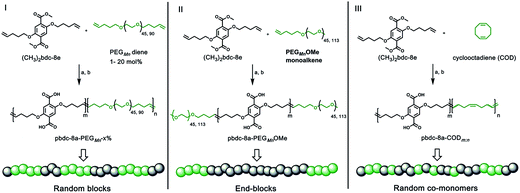
Monomers suitable for polymer formation were either purchased from commercially available sources or prepared via Williamson ether synthesis through a modified procedure from a previous polyMOF report (Scheme S1†).38 For this study, the MOF-forming block was synthesized from a methyl ester protected monomer termed (CH3)2bdc-8e (Scheme 1). (CH3)2bdc-8e and alkene-modified PEG (diene or monoalkene) were copolymerized via acyclic diene metathesis (ADMET) polymerization using Grubbs 2nd generation catalyst (G2) to afford two different types of PEG block copolymer esters: (i) random AB block copolymers, or (ii) capped AB2 triblock copolymers (wherein the “A” block is the (CH3)2bdc-8e block and the “B” block is the PEG block, Scheme 1). Random AB PEG block copolymers are designated as pbdc-8e-PEGMn-x% (where pbdc indicates a polymer prepared from (CH3)2bdc-8e, “8” refers to the alkane spacings between each H2bdc unit, “e” indicates polymer ester, Mn indicates the molecular weight of PEG used in the synthesis, and “x%” indicates the mol% of reactive PEG diene in the reaction feed). AB2 triblock copolymers are denoted as pbdc-8e-PEGMnOMe (where OMe denotes a capped pbdc-8e polymer). For polymers containing COD, monomer (CH3)2bdc-8e was polymerized via ADMET polymerization using Hoveyda–Grubbs 2nd Generation catalyst, followed by ring-opening metathesis polymerization (ROMP, Scheme 1) of COD to afford random AB COD block copolymers pbdc-8e-CODm:n, (where m![[thin space (1/6-em)]](https://www.rsc.org/images/entities/char_2009.gif) :
:![[thin space (1/6-em)]](https://www.rsc.org/images/entities/char_2009.gif) n indicates the molar ratio of (CH3)2bdc-8e:COD, Scheme S4, Fig. S13–S15†). All of the aforementioned polymers were hydrolyzed to afford block copolymer acid ligands pbdc-8a-PEGMn-x%, pbdc-8a-PEGMnOMe, and pbdc-8a-CODm:n, where “a” indicates the block copolymer contains carboxylic acid groups (Scheme 1, Fig. S16–S26†).
n indicates the molar ratio of (CH3)2bdc-8e:COD, Scheme S4, Fig. S13–S15†). All of the aforementioned polymers were hydrolyzed to afford block copolymer acid ligands pbdc-8a-PEGMn-x%, pbdc-8a-PEGMnOMe, and pbdc-8a-CODm:n, where “a” indicates the block copolymer contains carboxylic acid groups (Scheme 1, Fig. S16–S26†).
A combination of 1H NMR and gel-permeation chromatography (GPC) were used to characterize the block copolymer esters (Table 1). For all block copolymers, the relative weight percent of (CH3)2bdc-8e to co-monomers were calculated using 1H NMR and ranged between 50–90%. 1H NMR was also used to determine incorporation of PEG or COD to pbdc-8e by examining the ratios of small-molecule repeat units (ethylene glycol or COD) to (CH3)2bdc-8e present in the sample Table S1, ESI†). Relative molecular weights were determined via GPC for the polymer esters using PMMA as a calibration standard (Fig. S27†). Molecular weight distributions were narrow, as the dispersity was <2.0 for polymers containing PEG (pbdc-8e-PEGMn-x% and pbdc-8e-PEGMnOMe); this is indicative of the narrow dispersity of the PEG block. In contrast, block copolymers prepared with COD have broader dispersities, which are reflective of ADMET being a step-growth polymerization (Table 1). Polymer acid ligands were too polar to evaluate by GPC. However, 1H NMR analysis was performed on the final carboxylic acid-containing polymer ligands, revealing that the ratios between H2bdc units and the other polymer block are reflective of those determined for the ester polymer precursors (Fig. S16–S26†).
| Ligand | wt% pbdc-8e (1H NMR)a | M n (GPC) | Đ (GPC) |
|---|---|---|---|
| a The weight percentages of (CH3)2bdc-8e in the block copolymers were calculated using the following formula: wt% pbdc-8e = (ratio of (CH3)2bdc-8e × M.W.(CH3)2bdc-8e)/[(ratio of (CH3)2bdc-8e × M.W.(CH3)2bdc-8e) + (ratio of co-monomer × M.W.co-monomer)] × 100%. b Purified forms of bifunctionalized pbdc-8e-PEGMnOMe are represented. | |||
| pbdc-8e-PEG2000-2% | 93 | 18![[thin space (1/6-em)]](https://www.rsc.org/images/entities/char_2009.gif) 700 700 |
1.3 |
| pbdc-8e-PEG2000-20% | 56 | 14![[thin space (1/6-em)]](https://www.rsc.org/images/entities/char_2009.gif) 700 700 |
1.4 |
| pbdc-8e-PEG4000-1% | 90 | 18![[thin space (1/6-em)]](https://www.rsc.org/images/entities/char_2009.gif) 700 700 |
1.5 |
| pbdc-8e-PEG4000-10% | 52 | 16![[thin space (1/6-em)]](https://www.rsc.org/images/entities/char_2009.gif) 000 000 |
2.2 |
| pbdc-8e-PEG2000OMeb | 84 | 20![[thin space (1/6-em)]](https://www.rsc.org/images/entities/char_2009.gif) 300 300 |
1.6 |
| pbdc-8e-PEG5000OMeb | 52 | 19![[thin space (1/6-em)]](https://www.rsc.org/images/entities/char_2009.gif) 900 900 |
1.4 |
| pbdc-8e-COD1:1 | 85 | 17![[thin space (1/6-em)]](https://www.rsc.org/images/entities/char_2009.gif) 200 200 |
2.8 |
| pbdc-8e-COD2:1 | 92 | 17![[thin space (1/6-em)]](https://www.rsc.org/images/entities/char_2009.gif) 500 500 |
2.8 |
| pbdc-8e-COD10:1 | 98 | 26![[thin space (1/6-em)]](https://www.rsc.org/images/entities/char_2009.gif) 500 500 |
3.5 |
Although ADMET polymerization is a useful technique for synthesizing MOF-forming polymers, because it produces large polymers with precise alkyl spacings between H2bdc, the method lacks control over degree of polymerization and it is generally not ideal for making block copolymers.48 Therefore, fractionation by automated silica gel column chromatography was used to characterize the components of the block copolymer ester ligands. Fractionation of pbdc-8e-PEGMn-x% revealed that block copolymers of pbdc-8e predominantly lacked the PEG block when low loadings of PEG (1–2 mol%) were used for the synthesis, whereas with larger loadings of PEG (10–20 mol%) resulted in block copolymers with PEG chains (as gauged by 1H NMR, Fig. S28 and S29, Tables S2 and S3†). For pbdc-8e-PEGMnOMe polymers, fractionation revealed that the polymers contained a mixture of unfunctionalized (i.e., no PEG block) pbdc-8e-u, monofunctionalized (i.e., one PEG block) block copolymers, and bifunctionalized (i.e., two PEG blocks) pbdc-8e-u (as gauged by 1H NMR end-group analysis, Fig. S30, Table S4†). Purified forms of bifunctionalized pbdc-8e-PEGMnOMe were obtained via column chromatography and were used for the synthesis of polyMOFs (Table 1). For block copolymers of pbdc-8e-CODm:n, no noticeable fractionation could be achieved, suggesting an even distribution of COD throughout all polymer chains within pbdc-8e-CODm:n samples (Fig. S31, Table S5†).
Formation and morphology control of UiO-66 BCPMOFs
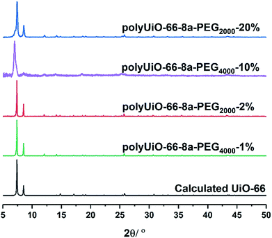
Zirconium-based UiO-66 was selected for BCPMOF formation because of the high chemical stability of this MOF and the large number of studies using it in the literature.49 Preparation of polyUiO-66 was achieved with ZrCl4, the corresponding polymer ligand, and excess formic acid modulator under solvothermal conditions for 48 h.38 The block-polyUiO-66 were dissolved and analysed to confirm the presence and integrity of the block copolymer ligands during the solvothermal synthesis (Table S6, Fig. S32–S42†).BCPMOFs were first prepared from pbdc-8a-PEGMn-x% to investigate how the molecular weight of PEG and the amount of incorporated PEG affect the morphology of polyUiO-66. All polyMOFs formed from the pbdc-8a-PEGMn-x% series resulted in UiO-66 as confirmed from powder X-ray diffraction (PXRD, Fig. 1). Polymers with low amounts of PEG (pbdc-8a-PEG2000-2% or pbdc-8a-PEG4000-1%) yielded polyMOFs with much sharper primary PXRD reflections than those with larger amounts of PEG (pbdc-8a-PEG2000-20% or pbdc-8a-PEG4000-10%) where broadening was observed. Broadening of PXRD reflections is indicative of materials with reduced crystallinity. This may be simply due to the lower relative amount of MOF forming block in pbdc-8a-PEG2000-20% and pbdc-8a-PEG4000-10% (50% PEG by weight) when compared to pbdc-8a-PEG2000-2% and pbdc-8a-PEG4000-1% (10% PEG by weight) (Table 1). The molecular weight of the PEG block itself had an insignificant effect on the crystallinity of the polyMOFs, as gauged by PXRD (Fig. 1).
Scanning electron microscopy (SEM) revealed that the amount of the PEG component in pbdc-8a-PEGMn-x% has a significant effect on the morphology of block-polyUiO-66. Using reported synthetic conditions, UiO-66 prepared from H2bdc typically forms highly symmetric octahedra50 whereas using the homopolymer ligand pbdc-8a produces a crystalline film of polyUiO-66 with an “interlaced” morphology.38 In contrast, the BCPMOFs are able to produce both observed morphologies for UiO-66, yielding rounded octahedral structures or polyMOFs with an interlaced morphology simply by changing the block copolymer composition. PolyUiO-66 films prepared from pbdc-8a-PEG2000-2% and pbdc-8a-PEG4000-1% consisted of microcrystalline, intergrown octahedra, but with rounded edges (Fig. 2a and b). In contrast, polyUiO-66 prepared from pbdc-8a-PEG2000-20% and pbdc-8a-PEG4000-10% produced films with an interlaced morphology with interwoven facets (Fig. 2c and d). The morphology of these materials correlates with the crystallinity observed by PXRD (Fig. 1), for the sharper reflections in the pbdc-8a-PEG2000-2% or pbdc-8a-PEG4000-1% block polyMOFs correspond to the observed octahedra, whereas the broader reflections produced by 8a-PEG2000-20% or pbdc-8a-PEG4000-10% correspond to block-polyUiO-66 with an interlaced morphology. Using a mixture of PEG and pbdc-8a homopolymers only yields polyUiO-66 with an interlaced morphology,38 showing that the presence of PEG alone did not allow for control of UiO-66 morphology (Fig. S43†).
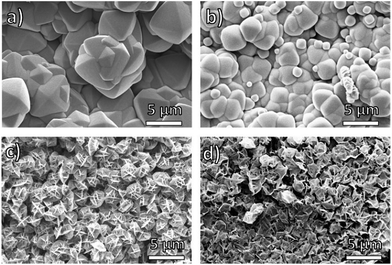 | ||
| Fig. 2 SEM images of polyUiO-66 prepared from block copolymer ligands: (a) pbdc-8a-PEG2000-2%; (b) pbdc-8a-PEG4000-1%; (c) pbdc-8a-PEG2000-20%; (d) pbdc-8a-PEG4000-10%. | ||
Dynamic light scattering (DLS) revealed that all block copolymers used in this study aggregate to form assemblies in solution, which suggest a cause for the morphological differences in BCPMOFs (Table S7†). At 13° scattering angle, pbdc-8a-PEG2000-20% and pbdc-8a-PEG4000-10% formed large aggregates in solution, with hydrodynamic radii of 101 nm and 72 nm, respectively (Fig. S44 and S45†). In contrast, pbdc-8a-PEG2000-2% and pbdc-8a-PEG4000-1% formed much smaller assemblies with hydrodynamic radii of 27 and 13 nm, respectively (Fig. S46 and S47†). Polymers will form assemblies with particular curvatures in order to minimize various thermodynamic factors including core chain stretching, corona chain crowding, and interfacial surface tension.51 When the weight fractions of two blocks are quite disparate, smaller assemblies with high curvature are preferred. Conversely, similar block weight fractions typically give rise to larger assemblies with low curvature, as is observed in the pbdc-PEG block copolymers in this study.
The origin of the morphologies observed in Fig. 2 is likely related to the accessibility of pbdc blocks to the growing crystal faces. During polyMOF growth, pbdc-8a-PEG2000-2% and pbdc-8a-PEG4000-1% generate controlled aggregation to yield octahedral morphology, but block copolymers with a large PEG content inhibit octahedra formation, reverting to the previously observed interlaced morphology for polyUiO-66.28,29,31 Hwang and coworkers17 observed similar behavior in MOF formation modulated by double hydrophilic block copolymers (DHBC) of PEG-b-poly(methacrylic acid) where higher proportions of polymer yielded smaller and more irregularly shaped morphologies compared to the native MOF. DHBCs have been commonly used to control the crystal morphologies of various hybrid materials.17,28,29,31 However, the pbdc-8a-PEGMn-x% polymers used in this study offer the unique advantage of providing both modulation of MOF crystal morphology and source of ligand for the framework itself.
To probe the effects of block copolymer architecture on polyUiO-66, pbdc-8a-PEGMnOMe ligands were used for polyUiO-66 synthesis. Following the same synthetic procedure described above, pure AB2 copolymers pbdc-8a-PEG2000OMe and pbdc-8a-PEG5000OMe were used to successfully synthesize polyUiO-66 (Fig. 3a). Block-polyUiO-66 prepared from crude (i.e., unfractionated) samples of pbdc-8a-PEG2000OMe and pbdc-8a-PEG5000OMe produced crystalline materials as assessed by PXRD (Fig. S48†). SEM reveals that all polyUiO-66 prepared from pbdc-8a-PEGMnOMe have an interlaced morphology (Fig. 3b, c and S49†). This result demonstrates that positioning of the PEG is important to control the shape of these materials; when PEG blocks are located within the backbone of the polymer ligand (e.g., pbdc-8a-PEG2000-2%) an octahedral morphology is observed (Fig. 2a and b), but when PEG blocks are located only at the ends of the polymer ligand (e.g., pbdc-8a-PEG2000OMe) the material retains the interlaced morphology (Fig. 3b and c).
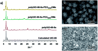 | ||
| Fig. 3 (a) PXRD patterns of polyUiO-66 prepared from purified pbdc-8a-PEGMnOMe. SEM images of polyUiO-66 prepared from: (b) pbdc-8a-PEG2000OMe and (c) pbdc-8a-PEG5000OMe. | ||
An additional reflection in the PXRD pattern at 2θ = 7.06° was present in all samples of polyUiO-66 prepared from pbdc-8a-PEGMnOMe ligands (Fig. 3a and S48†). This may be due to a distortion of the polyUiO-66 lattice to accommodate filling of the pore.38 Alternatively, this additional reflection may be the result of defects (e.g., missing clusters).52 Regardless of its origin, this additional reflection at 2θ = 7.06° is observed for all polyUiO-66 comprising the interlaced morphology (pbdc-8a-PEG2000-20%, pbdc-8a-PEG4000-10% and all pbdc-8a-PEGMnOMe), but not for polyUiO-66 materials with an octahedral morphology (pbdc-8a-PEG2000-2%, pbdc-8a-PEG4000-1%).
DLS was used to probe how aggregation of pbdc-8a-PEGMnOMe ligands affects the morphology of block-polyUiO-66. As in the pbdc-8a-PEGMn-x% series, small polymer assemblies yield larger polyMOF crystals. The hydrodynamic radii (13° scattering angle) of pbdc-8a-PEG2000-OMe and pbdc-8a-PEG5000-OMe were 129 nm and 33 nm, leading to polyMOFs with crystal sizes of approximately 3 μm and 1 μm, respectively (Fig. S50 and S51†).
Block copolymer ligands pbdc-8a-CODm:n were investigated to determine the effects of polymer composition on polyUiO-66. In contrast to PEG-based block copolymers, the polyCOD block is significantly more hydrophobic, making it less likely to interact with growing MOF surfaces. All pbdc-8a-CODm:n produced polyUiO-66 with good crystallinity (Fig. S52†). SEM imaging shows both pbdc-8a-COD2:1 and pbdc-8a-COD1:1 produced polyUiO-66 with intergrown octahedral morphologies that are different than those previously reported for polyUiO-66 (Fig. S53†). PolyUiO-66 prepared from pbdc-8a-COD10:1 produced an interlaced morphology and a new, but related morphology (Fig. S54†). The variability in morphology control may be attributed to pbdc-8a-COD10:1 containing broad polymer dispersities and the block copolymer containing a greater proportion of H2bdc (98% wt). All polymers containing COD showed the presence of large assemblies in solution based on DLS (Rh > 50 nm, Table S7, Fig. S55–S57†).
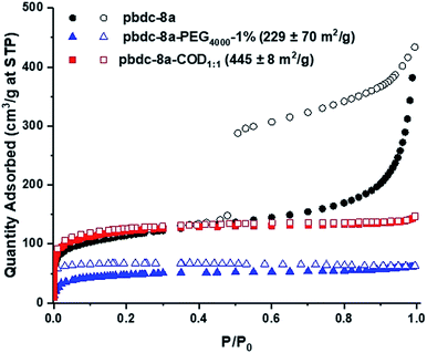
The morphology of the polyUiO-66 materials affected the porosity of the materials, as characterized by N2 gas adsorption. polyUiO-66 generated from pbdc-8a produces a polyMOF with a Brunauer–Emmett–Teller (BET) surface area of 340–420 m2 g−1 with the interlaced morphology resulting in a mesoporous material, as indicated by a type IV isotherm with a hysteresis loop.38 Similarly, block-polyUiO-66 with an interlaced morphology (produced from pbdc-8a-PEG2000-20%, pbdc-8a-PEG4000-10%, and all pbdc-8a-PEGMnOMe polymer ligands) produced the expected type IV isotherms (Fig. S58†). However, changing the morphology of block-polyUiO-66 to intergrown octahedron (from pbdc-8a-PEG4000-1%, pbdc-8a-COD1:1, and pbdc-8a-COD2:1 polymer ligands) yielded type I isotherms, which are indicative of a microporous material (Fig. 4 and S59†). One exception was block-polyUiO-66 prepared from pbdc-8a-PEG2000-2%, for which there was no accessible surface area, perhaps due to pore filling of the polyMOF by PEG (Fig. S60a†). CO2 adsorption at 195 K was used to determine accessibility of the pores in pbdc-8a-PEG2000-2%, which gave a surface area of 151 ± 3 m2 g−1 (Fig. S60b†). Analysis of the pore width distribution of all block-polyUiO-66 showed two different populations, one centred at between 9–13 Å, and another population between 14–40 Å, consistent with previous reports on polyUiO-66 (Fig. S61†). It should be noted that for block-polyUiO-66 with intergrown octahedron, the pore width distribution between 14–40 Å is significantly reduced when compared to the distribution of block-polyUiO-66 that yielded the interlaced morphology. Based on these results, it can be proposed that changing the morphology influences the formation of mesopores. As such, using block copolymer ligands may be a way to fine-tune the porosity of polyMOF materials.
Synthesis and characterization of IRMOF-1 type BCPMOFs
The successful preparation of block-polyUiO-66 prompted study of a different MOF, namely Zn-based IRMOF-1. polyIRMOF-1 was synthesized under solvothermal conditions at 100 °C for 24 h to yield off-white solids or an off-white suspension.37 Analysis by PXRD confirmed the preparation of polyIRMOF-1 using all block copolymers prepared in this study (Fig. 6 and S62–S64†). All block-polyIRMOF-1 displayed a broad amorphous phase, centred at 2θ ∼ 22° that can be attributed uncoordinated block copolymer present in the material (Fig. S62–S64†). To confirm the integrity of the copolymers, block-polyIRMOF-1 were digested and analysed by 1H NMR (Fig. S65–S73†), which showed the polymer ligands were intact. Furthermore, the stability of all block-polyIRMOF-1 were tested by storing activated, dried samples under ambient conditions. In general, block-polyIRMOF-1 produced PXRD patterns with broad reflections after 10 min of exposure to air (Fig. S74–S76†), but the crystallinity of these materials could be regenerated by immersion of solids in DMF at 60 °C for 1 h (Fig. S77†).37 The ability to restore the crystallinity of block-polyIRMOF-1 under mild conditions could make these materials reusable.37,41SEM images of block-polyIRMOF-1 revealed that block copolymer ligands notably affect the size and uniformity of these materials, with size control achieved through block copolymer composition and relative weight fractions. Homopolymer pbdc-8a used to synthesize polyIRMOF-1 produces microcrystalline cubes that are irregular in size and dimensionality (Fig. 5a). By comparison, PEG block copolymers pbdc-8a-PEG2000-2% and pbdc-8a-PEG4000-1% produce microcrystalline cubes that are uniform in shape and size (Fig. 5b and c), measuring at 1.8 ± 0.3 μm for pbdc-8a-PEG2000-2% (Fig. 5b) and measuring at 1.0 ± 0.3 μm for pbdc-8a-PEG4000-1% (Fig. 5c). At higher amounts of PEG, nanocrystallites of block-polyIRMOF-1 with a uniform cubic morphology and size were produced (Fig. 5d–f), measuring at 540 ± 200 nm for pbdc-8a-PEG2000-20% and measuring at 320 ± 90 nm for pbdc-8a-PEG4000-10%. Block-polyIRMOF-1 prepared from ligands pbdc-8a-PEGMnOMe also resulted in distinct shape and size behaviour (Fig. S78†). With increasing PEG molecular weight, the size of the particles significantly decreased, as gauged by SEM. In contrast, block-polyIRMOF-1 prepared from pbdc-8a-CODm:n ligands did not show good size and shape control, with the exception of pbdc-8a-COD1:1, which also gave relatively monodisperse, rounded particles (Fig S79†). To ensure that PEG alone was not the result of morphology control, polyIRMOF-1 was synthesized using a physical mixture of homopolymer pbdc-8a and PEG (at 1 and 10 mol%), which was unable to provide uniform shape and size of these materials (Fig. S80†). These results suggest that the PEG block copolymers play an important role generating metastable intermediates during MOF formation, similarly to those observed for DHBCs. Overall, using block copolymer ligands show a promising route to control the regularity of IRMOF-1 and related scaffolds.
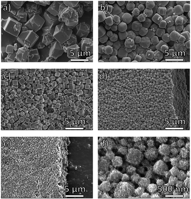 | ||
| Fig. 5 SEM images of polyIRMOF-1 prepared from polymer ligands: (a) pbdc-8a; (b) pbdc-8a-PEG2000-2%; (c) pbdc-8a-PEG4000-1%; (d) pbdc-8a-PEG2000-20%; (e and f) pbdc-8a-PEG4000-10%. | ||
The ability to transform block copolymers into crystalline materials with cubic morphologies is highly unusual and is rarely observed for polymers. Recently, Kim reported block copolymer assemblies with bicontinuous cubic membranes53 and Matyjaszewski reported cubosomes assembled from poly(ionic liquid) block copolymers.54 The observation of cubic structures of block-polyIRMOFs and highly faceted morphologies in block-polyUiO-66 above demonstrates the power of block copolymer MOF formation as a general strategy to achieve non-traditional polymer morphologies. As in block-polyUiO-66 discussed above, the lower hydrodynamic radii of parent block copolymers leads to larger BCPMOF crystals. In the case of pbdc-8a-PEG4000-10%, the BCPMOF crystals were small enough to perform DLS experiments, which gave hydrodynamic radii of 274 nm and 308 nm at 90° and 13° scattering angle, respectively, which indicates a narrow distribution of particle sizes (Fig. S81, Table S7†) that are consistent with the particle sizes observed by SEM (Fig. 5f).
Controlling the shape and size of MOFs using block copolymers offers potential for new methods to prepare MOF-composite materials. Recent efforts by Johnson41 and Kitagawa55 demonstrated the ability to transform block copolymers into metal–organic materials with successive phase separation between MOF domains and polymer domains. Similarly, it is speculated that BCPMOFs observed in this work (Fig. 5f) exhibit phase separation, but with larger MOF-domains. In the future, it is anticipated that the ability to control the shape and size of BCPMOFs will allow for the preparation of densely-packed polymer–MOF composite materials.
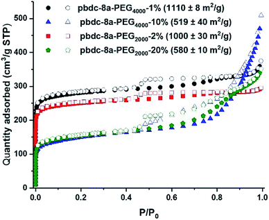
Nitrogen gas adsorption confirmed that synthesis of block-polyIRMOF-1 can produce porous materials with exceptional surface areas and interesting properties. Indeed, BET surface areas of 550–1100 m2 g−1 were achieved for block-polyIRMOF-1 using pbdc-8a-PEGMn-x% type polymers (Fig. 6). BET surface areas of ∼800–900 m2 g−1 were achieved for polyIRMOF-1 prepared from crude pbdc-8a-PEGMnOMe (Fig. S82†), and ∼300–700 m2 g−1 for polyIRMOF-1 prepared from pbdc-8a-CODm:n (Fig. S83†). For block-polyIRMOF-1 prepared from pbdc-8a-PEGMn-x% type polymers, hysteresis was observed in the N2 isotherm, regardless of the amount or molecular weight of PEG copolymer ligand used in the synthesis. Similarly, block-polyIRMOF-1 prepared from pbdc-8a-PEGMnOMe also produced a hysteresis in the isotherm, indicative of a mesoporous material. In contrast, N2 isotherms of samples prepared from pbdc-8a-CODm:n did not exhibit hysteresis. A possible explanation for the differences in behaviour between PEG block polyMOFs and COD block polyMOFs may be due to the size-distribution of polymer blocks in the ligands. For pbdc-8a-PEGMn-x% and pbdc-8a-PEGMnOMe, polymer ligands are prepared from PEG macromonomers that have the potential to create large regions of PEG-only domains and pbdc-8a-only domains within these copolymer ligands; in turn, PEG may be accommodated in the BCPMOF if mesopores are introduced. In contrast, pbdc-8a-CODm:n type ligands are prepared from small molecule COD that is evenly distributed throughout all the polymer chains; this in turn creates smaller COD domains within pbdc-8a-CODm:n that do not need accommodation by mesopore formation. On the whole, these results demonstrate a promising route to the preparation of highly porous BCPMOF materials with tuneable porosity.
Conclusions
The use of block copolymer ligands was successfully shown to produce polyMOFs with controlled morphologies and sizes, using UiO-66 and IRMOF-1 as crystal scaffolds. This study demonstrates how block copolymer ligands with various compositions, sizes, and arrangements can affect the formation and properties of polyMOF materials. To the best of our knowledge, BCPMOFs are the only system where the polymer ligand is both the modulator and the provider of ditopic ligands for MOF formation, making them unique MOF–polymer hybrid materials that take advantage of block copolymer properties. Understanding the role that polymers play in polyMOFs will ultimately allow us to design materials with processable and desirable properties.Conflicts of interest
There are no conflicts to declare.Acknowledgements
The authors would like to thank Prof. Zhenjie Zhang, Pablo Quijano Velasco, and Zhonghuan Renee Lou for assistance with these studies. SEM imaging was performed at the San Diego Nanotechnology Infrastructure (SDNI) of U.C. San Diego, a member of the National Nanotechnology Coordinated Infrastructure, which is supported by the National Science Foundation (Grant ECCS-1542148). This work was supported by a grant from the Department of Energy, Office of Basic Energy Sciences, Division of Materials Science and Engineering under Award No. DE-FG02-08ER46519 (S. M. C.). S. A. was supported, in part, by a fellowship from the Department of Education Graduate Assistance in Areas of National Need (GAANN) Training Grant and the Inamori Foundation.References
- K. C. Bentz and S. M. Cohen, Angew. Chem., Int. Ed., 2018, 57, 14992–15001 CrossRef CAS.
- G. R. Whittell and I. Manners, Adv. Mater., 2007, 19, 3439–3468 CrossRef CAS.
- A. Winter and U. S. Schubert, Chem. Soc. Rev., 2016, 45, 5311–5357 RSC.
- T. Kitao, Y. Zhang, S. Kitagawa, B. Wang and T. Uemura, Chem. Soc. Rev., 2017, 46, 3108–3133 RSC.
- D. J. Tranchemontagne, J. L. Mendoza-Cortés, M. O'Keeffe and O. M. Yaghi, Chem. Soc. Rev., 2009, 38, 1257–1283 RSC.
- N. S. Bobbitt, M. L. Mendonca, A. J. Howarth, T. Islamoglu, J. T. Hupp, O. K. Farha and R. Q. Snurr, Chem. Soc. Rev., 2017, 46, 3357–3385 RSC.
- F. Fathieh, M. J. Kalmutzki, E. A. Kapustin, P. J. Waller, J. Yang and O. M. Yaghi, Sci. Adv., 2018, 4, eaat3198 CrossRef.
- W. P. Lustig, S. Mukherjee, N. D. Rudd, A. V. Desai, J. Li and S. K. Ghosh, Chem. Soc. Rev., 2017, 46, 3242–3285 RSC.
- J. M. Palomba, C. V. Credille, M. Kalaj, J. B. DeCoste, G. W. Peterson, T. M. Tovar and S. M. Cohen, Chem. Commun., 2018, 54, 5768–5771 RSC.
- M. Shivanna, Q.-Y. Yang, A. Bajpai, E. Patyk-Kazmierczak and M. J. Zaworotko, Nat. Commun., 2018, 9, 3080 CrossRef.
- L. Tan and B. Tan, Chem. Soc. Rev., 2017, 46, 3322–3356 RSC.
- M. S. Denny Jr, J. C. Moreton, L. Benz and S. M. Cohen, Nat. Rev. Mater., 2016, 1, 16078 CrossRef.
- T. Ishiwata, Y. Furukawa, K. Sugikawa, K. Kokado and K. Sada, J. Am. Chem. Soc., 2013, 135, 5427–5432 CrossRef CAS PubMed.
- T. Uemura, N. Yanai and S. Kitagawa, Chem. Soc. Rev., 2009, 38, 1228–1236 RSC.
- T. Uemura, T. Kaseda, Y. Sasaki, M. Inukai, T. Toriyama, A. Takahara, H. Jinnai and S. Kitagawa, Nat. Commun., 2015, 6, 7473 CrossRef PubMed.
- X. Cai, X. Deng, Z. Xie, S. Bao, Y. Shi, J. Lin, M. Pang and M. Eddaoudi, Chem. Commun., 2016, 52, 9901–9904 RSC.
- J. Hwang, T. Heil, M. Antonietti and B. V. K. J. Schmidt, J. Am. Chem. Soc., 2018, 140, 2947–2956 CrossRef CAS.
- M. Pang, A. J. Cairns, Y. Liu, Y. Belmabkhout, H. C. Zeng and M. Eddaoudi, J. Am. Chem. Soc., 2013, 135, 10234–10237 CrossRef CAS PubMed.
- X. Cheng, A. Zhang, K. Hou, M. Liu, Y. Wang, C. Song, G. Zhang and X. Guo, Dalton Trans., 2013, 42, 13698–13705 RSC.
- B. Zhang, J. Zhang, C. Liu, X. Sang, L. Peng, X. Ma, T. Wu, B. Han and G. Yang, RSC Adv., 2015, 5, 37691–37696 RSC.
- P. Falcaro, A. J. Hill, K. M. Nairn, J. Jasieniak, J. I. Mardel, T. J. Bastow, S. C. Mayo, M. Gimona, D. Gomez, H. J. Whitfield, R. Riccò, A. Patelli, B. Marmiroli, H. Amenitsch, T. Colson, L. Villanova and D. Buso, Nat. Commun., 2011, 2, 237 CrossRef.
- S. Furukawa, J. Reboul, S. Diring, K. Sumida and S. Kitagawa, Chem. Soc. Rev., 2014, 43, 5700–5734 RSC.
- N. Stock and S. Biswas, Chem. Rev., 2012, 112, 933–969 CrossRef CAS.
- W. Cho, H. J. Lee and M. Oh, J. Am. Chem. Soc., 2008, 130, 16943–16946 CrossRef CAS.
- C. Guo, Y. Zhang, Y. Guo, L. Zhang, Y. Zhang and J. Wang, Chem. Commun., 2018, 54, 252–255 RSC.
- Q. Liu, J.-M. Yang, L.-N. Jin and W.-Y. Sun, Chem.–Eur. J., 2014, 20, 14783–14789 CrossRef CAS PubMed.
- M. Ma, D. Zacher, X. Zhang, R. A. Fischer and N. Metzler-Nolte, Cryst. Growth Des., 2011, 11, 185–189 CrossRef CAS.
- H. Cölfen, Macromol. Rapid Commun., 2001, 22, 219–252 CrossRef.
- F. C. Meldrum and H. Cölfen, Chem. Rev., 2008, 108, 4332–4432 CrossRef CAS PubMed.
- B. Weber, Chem.–Eur. J., 2017, 23, 18093–18100 CrossRef CAS PubMed.
- H. Cölfen and S. Mann, Angew. Chem., Int. Ed., 2003, 42, 2350–2365 CrossRef PubMed.
- X.-P. Zheng, S.-J. Xu, H.-L. Wu, Y.-F. Kong, Y. Wang, Q. Shen, Z.-L. Xu and G.-E. Chen, Inorg. Chem. Commun., 2018, 92, 91–94 CrossRef CAS.
- S. Wang, Y. Lv, Y. Yao, H. Yu and G. Lu, Inorg. Chem. Commun., 2018, 93, 56–60 CrossRef CAS.
- T.-H. Chen, L. Wang, J. V. Trueblood, V. H. Grassian and S. M. Cohen, J. Am. Chem. Soc., 2016, 138, 9646–9654 CrossRef CAS PubMed.
- T. Uemura, Y. Hoshino, S. Kitagawa, K. Yoshida and S. Isoda, Chem. Mater., 2006, 18, 992–995 CrossRef CAS.
- D. Jiang, T. Mallat, F. Krumeich and A. Baiker, Catal. Commun., 2011, 12, 602–605 CrossRef CAS.
- Z. Zhang, H. T. H. Nguyen, S. A. Miller and S. M. Cohen, Angew. Chem., Int. Ed., 2015, 54, 6152–6157 CrossRef CAS.
- S. Ayala, Z. Zhang and S. M. Cohen, Chem. Commun., 2017, 53, 3058–3061 RSC.
- Z. Zhang, H. T. H. Nguyen, S. A. Miller, A. M. Ploskonka, J. B. DeCoste and S. M. Cohen, J. Am. Chem. Soc., 2016, 138, 920–925 CrossRef CAS.
- G. E. M. Schukraft, S. Ayala, B. L. Dick and S. M. Cohen, Chem. Commun., 2017, 53, 10684–10687 RSC.
- M. J. MacLeod and J. A. Johnson, Polym. Chem., 2017, 8, 4488–4493 RSC.
- H. A. Kang, H. E. Bronstein and T. M. Swager, Macromolecules, 2008, 41, 5540–5547 CrossRef CAS.
- Y. Wang, M. Zhong, J. V. Park, A. V. Zhukhovitskiy, W. Shi and J. A. Johnson, J. Am. Chem. Soc., 2016, 138, 10708–10715 CrossRef CAS PubMed.
- D. Mozhdehi, J. A. Neal, S. C. Grindy, Y. Cordeau, S. Ayala, N. Holten-Andersen and Z. Guan, Macromolecules, 2016, 49, 6310–6321 CrossRef CAS.
- E. B. Berda, R. E. Lande and K. B. Wagener, Macromolecules, 2007, 40, 8547–8552 CrossRef CAS.
- C. M. Bates and F. S. Bates, Macromolecules, 2017, 50, 3–22 CrossRef CAS.
- S. Jain and F. S. Bates, Science, 2003, 300, 460–464 CrossRef CAS.
- L. Caire da Silva, G. Rojas, M. D. Schulz and K. B. Wagener, Prog. Polym. Sci., 2017, 69, 79–107 CrossRef CAS.
- M. Kim and S. M. Cohen, CrystEngComm, 2012, 14, 4096–4104 RSC.
- C. A. Trickett, K. J. Gagnon, S. Lee, F. Gándara, H.-B. Bürgi and O. M. Yaghi, Angew. Chem., Int. Ed., 2015, 54, 11162–11167 CrossRef CAS.
- Y. Mai and A. Eisenberg, Chem. Soc. Rev., 2012, 41, 5969–5985 RSC.
- M. J. Cliffe, W. Wan, X. Zou, P. A. Chater, A. K. Kleppe, M. G. Tucker, H. Wilhelm, N. P. Funnell, F.-X. Coudert and A. L. Goodwin, Nat. Commun., 2014, 5, 4176 CrossRef CAS.
- Y. La, C. Park, T. J. Shin, S. H. Joo, S. Kang and K. T. Kim, Nat. Chem., 2014, 6, 534–541 CrossRef CAS.
- H. He, K. Rahimi, M. Zhong, A. Mourran, D. R. Luebke, H. B. Nulwala, M. Möller and K. Matyjaszewski, Nat. Commun., 2017, 8, 14057 CrossRef.
- N. Hosono, M. Gochomori, R. Matsuda, H. Sato and S. Kitagawa, J. Am. Chem. Soc., 2016, 138, 6525–6531 CrossRef CAS PubMed.
Footnote |
| † Electronic supplementary information (ESI) available: Experimental procedures, 1H NMR, GPC, PXRD, SEM, DLS, and BET data. See DOI: 10.1039/c8sc04250k |
| This journal is © The Royal Society of Chemistry 2019 |

