
Ultrathin CdS shell-sensitized hollow S-doped CeO2 spheres for efficient visible-light photocatalysis†
Ning-Chao
Zheng
ab,
Ting
Ouyang
a,
Yibo
Chen
a,
Zhu
Wang
*ab,
Di-Yun
Chen
b and
Zhao-Qing
Liu
 *a
*a
aSchool of Chemistry and Chemical Engineering/Institute of Clean Energy and Materials/Key Laboratory for Water Quality and Conservation of the Pearl River Delta, Ministry of Education, Guangzhou University, Guangzhou 510006, China. E-mail: wangzhu@gzhu.edu.cn; lzqgzu@gzhu.edu.cn
bSchool of Environmental Science and Engineering/Guangdong Provincial Key Laboratory for Radionuclides Pollution Control and Resources, Guangzhou University, Guangzhou 510006, China
First published on 26th December 2018
Abstract
Highly efficient photocatalysts are urgently needed with the ever-increasing problems of environmental pollution and the energy crisis. Herein, we report a shape-controlled binary photocatalyst consisting of S-doped CeO2 hollow spheres sensitized with ultrathin CdS shells. The core-shelled CeO2−xSx@CdS composite is synthesized using a simple template-assisted method followed by anion-exchange and chemical bath deposition processes. Owing to the reduced band gap caused by the oxygen vacancies in the S-doped CeO2, and the CdS sensitization effect accelerating the interface carrier separation and transfer, the CeO2−xSx@CdS composite exhibits superior photocatalytic activity for hydrogen evolution (1147.2 μmol g−1 h−1) under visible-light illumination, which is 4.4, 11.1 and 94.8 times higher than that of CdS (258.2 μmol g−1 h−1), CeO2−xSx (103.0 μmol g−1 h−1) and CeO2 (12.1 μmol g−1 h−1), respectively. In addition, the composite displays highly efficient organic pollutant degradation (99.8% degradation of RhB within 25 min).
1. Introduction
Solar-driven photocatalysis as a green and sustainable technology is regarded as one of the most effective ways to address the energy- and environment-related issues.1–5 Particularly, the photocatalytic H2 evolution from water splitting driven by solar energy is highly attractive for converting solar energy to clean and renewable fuel.6 In this regard, the key lies in the design and synthesis of suitable photocatalysts that can harvest sunlight, facilitate photo-generated charge carrier separation, and thus accelerate surface redox reaction.7,8 To date, considerable progress has been made in developing heterojunction photocatalysts by coupling two or more active materials including oxides,9 sulfides,10,11 and nitrides12 for hydrogen evolution reaction. However, further developing commercial and large-scale photocatalysts is still limited by their low activity and high cost.13–15As a nontoxic, functional and abundant rare earth oxide, CeO2 has gained much attention in catalysis, fuel cells, and gas sensors owing to its controlled morphology, good structural stability, and high oxygen storage capacity.16–21 Notably, by virtue of the excellent redox potential between two oxidation states (Ce3+ → Ce4+), CeO2 can easily modulate different nonstoichiometric compositions (CeO2−x) with oxygen vacancies via anion doping.22,23 Consequently, the oxygen vacancies can be easily formed, transferred and eliminated. This unique feature can greatly improve the surface adsorption of reactants and largely enhance electron transfer, further making CeO2 a front-rank semiconductor photocatalyst.24,25 However, the photocatalytic activity of CeO2 in the visible-light region is still unsatisfactory due to its large band gap (Eg = 2.9 eV) and low charge carrier separation efficiency.26,27 Accordingly, many strategies including band gap engineering, morphology control, element doping, and surface modification have been developed to address these drawbacks.28–30 Among these methods, sulfur doping is a feasible and effective strategy to broaden the visible light-responsive range and suppress the recombination of photoinduced electron–hole pairs, thus improving visible-light photocatalytic performance.31,32 Unfortunately, it is still imperative to decorate and functionalize CeO2−xSx owing to the slightly enhanced photocatalytic performance.
In addition, the construction of a hollow sphere structure with high specific surface area and atomic utilization efficiency is another approach to extend the visible light-responsive range and speed up the separation of photoinduced electrons and holes.33,34 Cadmium sulfide (CdS) is an extensively employed photocatalyst because of its excellent band gap (∼2.4 eV) and sensitizing properties, which can not only harvest visible light but also rapidly separate photoinduced electron–hole pairs.35,36 Hence, it is highly desirable to design and develop a highly efficient and hollow photocatalyst by integrating the energy band-optimized CeO2−xSx with a CdS sensitizer.
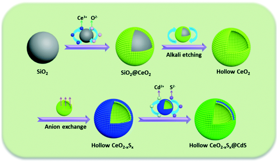
Herein, we present a “template + anion-exchange + chemical bath deposition” strategy for the fabrication of a shape-controlled photocatalyst composed of hollow S-doped CeO2 sphere and ultrathin CdS shell. The main step of this synthesis is illustrated in Scheme 1: uniform SiO2 spheres were firstly fabricated as the hard template and CeO2 nanoparticles were decorated onto the surface of the SiO2 spheres, followed by alkaline etching to obtain hollow CeO2 spheres. Then, a simple anion-exchange process was employed for the preparation of CeO2−xSx. Finally, the CeO2−xSx@CdS composite was obtained by a chemical bath deposition method. Impressively, the CeO2−xSx@CdS composite exhibited significantly enhanced photocatalytic activity compared with the pristine semiconductors. The enhanced activity could be ascribed to the sulfur doping and the synergistic effect between the hollow CeO2−xSx and CdS shell, which resulted in the extended visible-light absorption and improved interfacial carrier separation and transfer. These findings may provide new insight into designing and developing versatile photocatalyst materials with hollow structures for clean energy conversion and environmental pollutant degradation.
 | ||
| Scheme 1 Schematic illustration for the synthesis of the CeO2−xSx@CdS composite. | ||
2. Experimental
2.1. Reagents
Cerium nitrate hexahydrate (Ce(NO3)3·6H2O, ≥99.9%), cadmium nitrate tetrahydrate (CdN2O6·4H2O, ≥99.0%), cadmium diacetate dehydrate (Cd(Ac)2·2H2O), thiourea (CH4N2S, ≥99.0%), sodium sulfide (Na2S·9H2O, ≥98.0%), sodium sulfite anhydrous (Na2SO3, ≥97.0%), sodium hydroxide (NaOH, ≥96.0%), rhodamine B (RhB, C28H31ClN2O3, ≥99.5%), ethyl silicate (C8H20O4Si, AR), ethylene glycol ((CH2OH)2, AR), ammonium hydroxide (NH3·H2O, 25–28 wt%), and absolute ethanol (EtOH, AR) were purchased from Guangzhou Chemical Reagent Factory. All chemicals and reagents were of analytical grade and used without further purification.2.2. Synthesis of hollow CeO2−xSx@CdS catalysts
2.3. Characterization
The crystal phases of the samples were analyzed by X-ray diffraction (XRD, PANalytical, PW3040/60) with Cu Kα radiation (λ = 1.5418 Å). The morphologies and structures of the samples were characterized with field emission scanning electron microscopy (FE-SEM, JEOLJSM-7001F) and transmission electron microscopy (TEM, JEM2010-HR). The UV-visible diffuse reflectance spectra (DRS) of the samples were examined with a Hitachi UV-3010 spectrophotometer using BaSO4 as a reference. The steady-state/time-resolved photoluminescence emission spectra (345 nm excitation) were measured at room temperature with a fluorescence spectrophotometer (Edinburgh Instruments, FLSP-920). The Raman spectra were recorded with a Raman spectrometer (Bruker, VERTEX70). The detailed chemical composition of the samples was obtained by using X-ray photoelectron spectroscopy (XPS, ESCALab250). The surface areas were measured using a Micromeritics ASAP 2460 instrument (USA), and electron spin resonance (ESR) spectroscopy was performed on an EMXPlus-10/20 at 100 K.3. Results and discussion
3.1. Structure and morphology studies
The X-ray diffraction (XRD) patterns of the CeO2, CeO2−xSx and CeO2−xSx@CdS composites are shown in Fig. 1. The pattern of CeO2 with the characteristic peaks at 2θ = 28.6°, 33.1°, 47.5° and 56.3° were assigned to the (111), (200), (220) and (311) planes of the cubic fluorite CeO2 (JCPDS 34-0394). Interestingly, it can be observed that the intensity of the diffraction peaks decreases considerably for CeO2−xSx. This result is mainly ascribed to the sulfur doping in the CeO2 crystal structure, thereby reducing the crystallinity of CeO2. The XRD peaks of the CeO2−xSx@CdS composite indicate the coexistence of S-doped CeO2 and hexagonal CdS, and no other impurity diffraction peak was observed. The XRD results verified that the CeO2−xSx@CdS nanocomposite was successfully synthesised.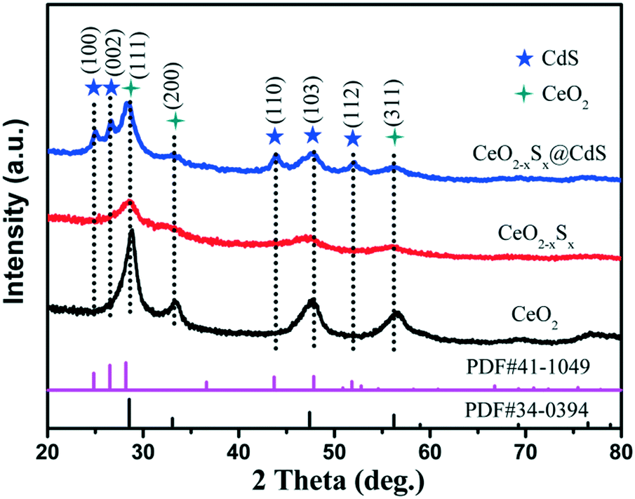 | ||
| Fig. 1 XRD patterns of the CeO2, CeO2−xSx and CeO2−xSx@CdS samples. | ||
The morphology and microstructure of the samples were investigated by SEM and TEM. The SiO2 nanospheres show a diameter of 250 nm (Fig. S1a†). Because of the abundant surface amidogen groups, Ce3+ cations could be absorbed and then the CeO2 particles were formed on the surface of the SiO2 spheres (Fig. S1b†).38 After removing the interior SiO2 cores by alkaline etching, the hollow CeO2 spheres with a diameter of 310 nm and rough surface were obtained. After sulfurization, the diameter of the hollow CeO2 spheres slightly decreased and their surface became smooth (Fig. S1c–e†). After chemical bath deposition, the ultimate CeO2−xSx@CdS composite was obtained. As shown in Fig. 2a, the SEM image of the CeO2−xSx@CdS composite shows that the CdS nanoparticles were uniformly coated on the surface of the CeO2−xSx hollow spheres. The sample is about 330 nm in diameter and the thickness of the CdS shell is about 10 nm. The morphology and structure of the CeO2−xSx@CdS composite were further analyzed by TEM. The results showed that the CeO2−xSx@CdS composite possesses an inner hollow structure (Fig. 2b). The magnified TEM image in Fig. 2c further demonstrates an intact hollow sphere structure, in which the shell thickness of CeO2−xSx@CdS is about 40 nm, and the radius is around 125 nm. From the HRTEM image of the CeO2−xSx@CdS composite (Fig. 2d), the lattice fringes with a d-spacing of 0.312 and 0.271 nm can be seen, corresponding to the spacing of the (111) and (200) planes of the cubic fluorite structured CeO2, while the lattice fringes with a d-spacing of 0.359 nm match well with the (100) plane of hexagonal CdS. Meanwhile, the CeO2−xSx@CdS composite was analyzed by EDX mapping (Fig. 2e–h and S2†). The elemental maps indicate the uniform distribution of Ce, O, S and Cd in the shell of the hollow CeO2−xSx@CdS spheres, in line with that of the CdS nanoparticles homogeneously coated on the surface of the CeO2−xSx hollow spheres.
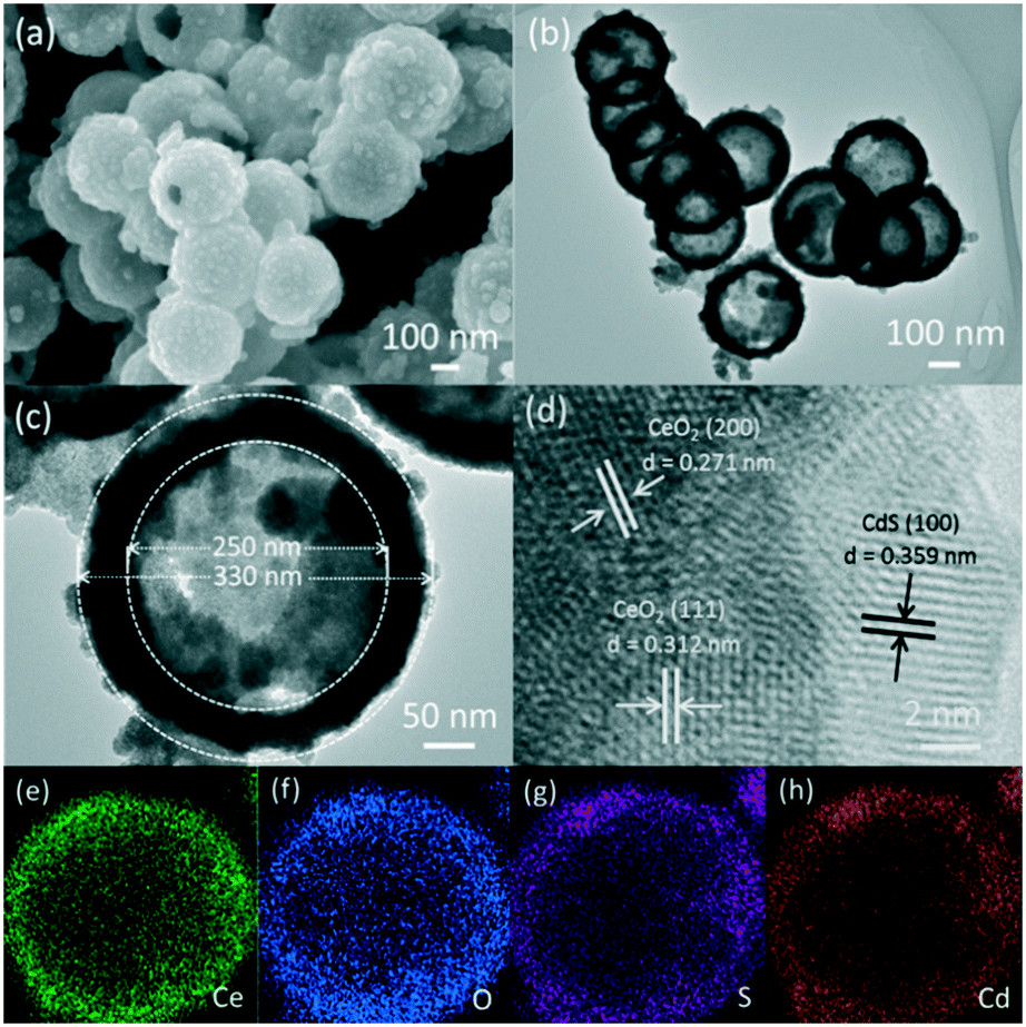 | ||
| Fig. 2 (a) SEM image, (b and c) TEM images, (d) HRTEM image, and (e–h) elemental mapping of the CeO2−xSx@CdS composite: (e) Ce, (f) O, (g) S and (h) Cd. | ||
In addition, the surface areas of the samples were examined by nitrogen adsorption–desorption isotherms. The BET surface areas of CeO2, CeO2−xSx, CdS and CeO2−xSx@CdS were calculated to be ca. 25.52, 27.42, 14.06 and 47.41 m2 g−1, respectively (Fig. S3†). These results suggest that the coating of the thin CdS shell on the surface of CeO2−xSx could effectively enhance the surface area. As a consequence, the more exposed active sites of the CeO2−xSx@CdS composite could be beneficial to improve the photocatalytic activity.
3.2. XPS analysis
X-ray photoelectron spectroscopy (XPS) was employed to analyze the elemental compositions and chemical states of the CeO2, CeO2−xSx, and CeO2−xSx@CdS samples (Fig. S4†). Fig. 3a shows that the Ce 3d peak can be fitted into eight peaks, which can be assigned to 3d3/2 spin–orbit states (labeled u) and 3d5/2 states (labeled v).39 The spectra of 885.1 eV (v′) and 904.4 eV (u′) assigned to Ce3+ are observed, indicating the coexistence of Ce3+ and Ce4+ in the CeO2−xSx and CeO2−xSx@CdS samples. This result suggests that the oxygen vacancies were formed in the CeO2 lattice.40 The quantitative analysis of the Ce 3d peak position is also summarized (Table S1†). The percentage of Ce3+ (Ce3+ species calculated based on the relative areas of the v′/u′ peaks according to the eqn S1†) is estimated to be ∼27.8% for the CeO2−xSx@CdS samples. Therefore, the percentage of oxygen vacancies is ∼13.9% in the region of the surface and sub-surface.29 Moreover, the existence of oxygen vacancies was also investigated by electron spin resonance (ESR) spectroscopy (Fig. S5†). It can be clearly observed that the ESR signal of CeO2 is a horizontal line. However, the CeO2−xSx and CeO2−xSx@CdS samples exhibit a high intensity ESR signal peak at g = 2.011, which could be identified as the electrons trapped by the abundant oxygen vacancies, confirming the enhanced content of oxygen vacancies after S-doping and coating of the ultrathin CdS shell.41 For the spectra of O 1s (Fig. 3b), the peak at 529.4 eV can be ascribed to the lattice oxygen in CeO2, and another peak at 531.4 eV can be attributed to the adsorbed oxygen and adsorbed water on the surface.42,43 Meanwhile, two broadened peaks of S 2p at around 161.7 eV (S 2p3/2) and 163.2 eV (S 2p1/2) are assigned to the sulfide (S2−) (Fig. 3c).44,45 The peaks centered at 405.1 eV (Cd 3d5/2) and 411.8 eV (Cd 3d3/2) are attributed to Cd2+ in CeO2−xSx@CdS (Fig. 3d).46,47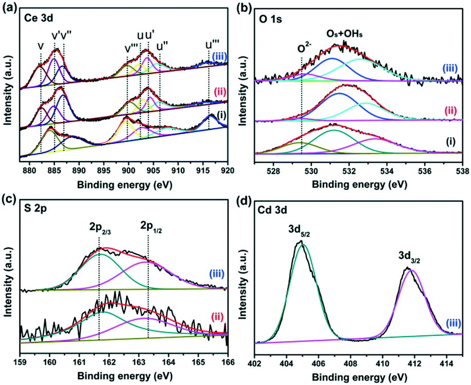 | ||
| Fig. 3 High-resolution XPS spectra of (a) Ce 3d, (b) O 1s, (c) S 2p and (d) Cd 3d; (i), (ii) and (iii) represent CeO2, CeO2−xSx, and CeO2−xSx@CdS, respectively. | ||
3.3. Optical properties
The UV-vis diffuse reflectance spectra of the samples were measured to investigate their light absorption characteristics. The CeO2 hollow spheres exhibit poor absorption of visible light and the absorption edge is around 420 nm (Fig. 4a), which is consistent with previous reports.48,49 However, the CeO2−xSx and CeO2−xSx@CdS samples exhibit extensively enhanced optical absorption with the edge extended to 540 nm and 560 nm, respectively (Fig. S6a and S7a†). One of the reasons is that the oxygen vacancies generated by the sulfur doping in CeO2 could reduce the electronic band gap of CeO2.50 And another one is the sensitization of CeO2−xSx by the deposited CdS shell.26 These UV-vis diffuse reflectance spectra are also in accordance with the color evolution of the three samples (Fig. 4a, inset), in which the color of the samples turned from pale yellow to brown and finally to deep yellow with the sulfur doping and coating of the ultrathin CdS shell.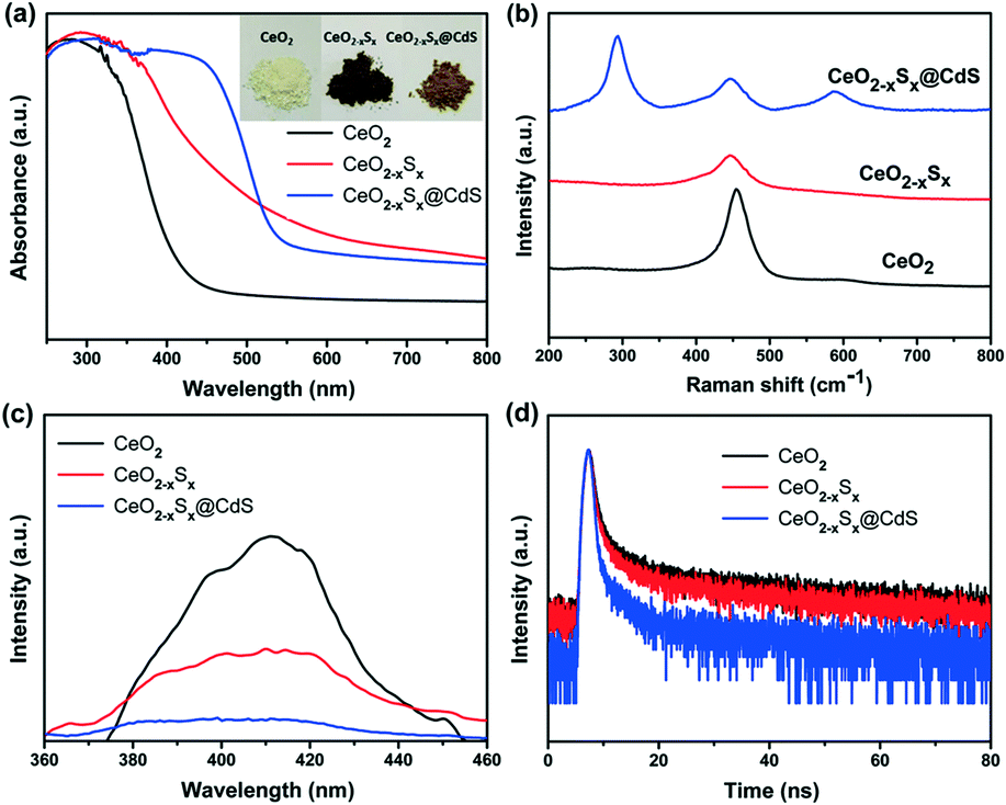 | ||
| Fig. 4 (a) UV-visible diffuse reflectance absorption spectra, (b) Raman spectra, (c) photoluminescence spectra, and (d) TRPL spectra of the CeO2, CeO2−xSx and CeO2−xSx@CdS samples. | ||
Raman spectroscopy was used to study the structural information of the samples. A strong Raman peak at ∼460 cm−1 is detected in the CeO2 sample (Fig. 4b), which could be assigned to the F2g peak originating from the symmetrical stretching of the Ce–O vibrational unit in the fluorite-type structure.51 Interestingly, the Raman peak of CeO2−xSx shifted to a lower wavenumber compared to that of CeO2. The shift can be attributed to the increased oxygen vacancies in the crystalline structure caused by S-doping.22 Moreover, it can be seen that the CeO2−xSx@CdS nanocomposite shows two strong Raman peaks at ∼300 and ∼600 cm−1, which are assigned to the first-order and second-order transverse optical phonon modes, respectively.52
In order to estimate the charge recombination and migration efficiency of the samples, photoluminescence (PL) measurements were carried out under 345 nm wavelength excitation. CeO2 has a strong PL emission peak at around 410 nm (Fig. 4c), which may be attributed to the defect levels localized between the O 2p and Ce 4f levels.53,54 As a comparison, the peak intensities of all the samples could be listed as follows: CeO2 > CeO2−xSx > CeO2−xSx@CdS, indicating that CeO2−xSx@CdS possesses the lowest recombination rate of photoinduced electrons and holes. The time-resolved PL (TRPL) decay spectra further prove this conclusion. The TRPL spectra were fitted with a biexponential function and yield a short lifetime component (τ1) and long lifetime component (τ2) (Fig. 4d), and an average PL lifetime (τ) was computed for comparison (Table S2†).55,56 Significantly, the average PL lifetime of CeO2−xSx@CdS is 8.031 ns, which is shorter than that of CeO2−xSx (15.182 ns) and CeO2 (17.369 ns). This indicates that the introduction of S species and the coating of the ultrathin CdS shell can effectively enhance charge transfer and separation.57
3.4. Photoelectrochemical performance evaluation
Photoelectrochemical measurements of the as-prepared materials were conducted in an aqueous electrolyte with 0.25 M Na2S and 0.35 M Na2SO3. Fig. 5a shows the linear sweep voltammetry curves of the samples under visible-light illumination in the potential range of −1.0 to 1.2 V (vs. Ag/AgCl). It can be seen that CeO2−xSx@CdS exhibits a high response current density (6.93 mA cm−2) compared with CeO2 (2.05 mA cm−2), CeO2−xSx (3.31 mA cm−2) and CdS (4.95 mA cm−2) at 1.2 V. The transient photocurrents were measured under visible-light irradiation and at a voltage of 0.4 V by switching the light on/off and the results are presented in Fig. 5b. It can be observed that CeO2 exhibited almost no response under visible-light irradiation. In contrast, the photocurrent density of CeO2−xSx@CdS is 8.65 μA cm−2, which is much higher than that of CeO2 (0.19 μA cm−2), CeO2−xSx (0.91 μA cm−2) and CdS (2.64 μA cm−2).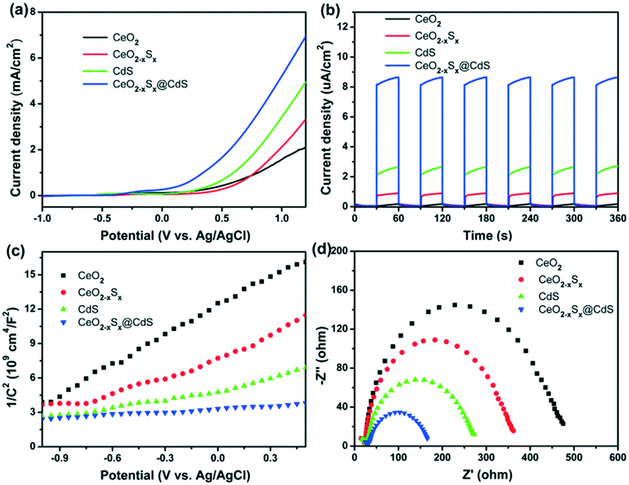 | ||
| Fig. 5 (a) Linear sweep voltammetry and (b) photocurrent response measurements of the CeO2, CeO2−xSx, CdS and CeO2−xSx@CdS samples under visible-light irradiation (λ > 420 nm) and at a voltage of 0.4 V. (c) Mott–Schottky plots and (d) EIS Nyquist plots of the CeO2, CeO2−xSx, CdS and CeO2−xSx@CdS samples. | ||
In addition, Mott–Schottky measurement provides another way to illustrate the enhanced photoelectrochemical activity. All the samples display positive slopes, indicating their n-type semiconductor nature (Fig. 5c).58 Furthermore, the electrochemical impedance spectra (EIS) were recorded to determine the charge transfer properties (Fig. 5d). The Nyquist plots of the samples were measured at 0.6 V bias under visible-light irradiation, in which the semicircles of the Nyquist plots gradually reduce in the following sequence: CeO2 > CeO2−xSx > CdS > CeO2−xSx@CdS, reflecting the faster electron transfer process in CeO2−xSx@CdS (Fig. S6b and S7b†). Therefore, the enhanced photoelectrochemical performance of CeO2−xSx@CdS could be ascribed to the doping of sulfur to reduce the band gap of CeO2 and the synergistic effect between the hollow CeO2−xSx and ultrathin CdS shell, which effectively improve the optical absorption in the visible light range and suppress the recombination of photoinduced electron–hole pairs.
3.5. Hydrogen evolution performance and mechanism analysis
Photocatalytic H2 generation activities over the as-prepared photocatalysts were evaluated under visible-light illumination (λ > 420 nm) with a mixed solution (0.25 M Na2S + 0.35 M Na2SO3) as the hole sacrificial agents. It is clearly seen that the CeO2 hollow spheres show very poor H2 evolution activity due to their intrinsic drawbacks (Fig. 6a). However, with the doping of sulfur and coating of the ultrathin CdS shell, the photocatalytic H2 evolution activity significantly increased. The CeO2−xSx@CdS composite exhibits excellent H2 evolution activity with a rate of up to 1147.2 μmol g−1 h−1, which is much higher than that of CeO2 (12.1 μmol g−1 h−1), CeO2−xSx (103.0 μmol g−1 h−1), CdS (258.2 μmol g−1 h−1) and many other photocatalysts (Fig. S6d and S7d and Table S3†). These results suggest that the doping of sulfur and coating of the ultrathin CdS shell played critical roles in enhancing the photocatalytic H2 generation activity. This is because the doping of sulfur could produce oxygen vacancies to reduce the band gap of CeO2, and the coating of the ultrathin CdS shell could not only generate sensitization but also enlarge the surface area to increase the contact between the catalyst and reactant. Moreover, the photogenerated electrons in the conduction band of CeO2−xSx could be easily transferred to the surface of CdS owing to their intimate interaction, which prevents the recombination of electron–hole pairs generated by CeO2−xSx. The photocatalytic degradation of the rhodamine B (RhB) dye was also tested with CeO2−xSx@CdS, and the degradation efficiency reached 99.8% within 25 min (Fig. S6c, S7c, S8, and S9†), which is superior to the performance of CeO2, CeO2−xSx, and CdS under the same conditions. The stability of the CeO2−xSx@CdS photocatalysts for H2 evolution was tested for 4 cycles, and the CeO2−xSx@CdS exhibited negligible attenuation in the prolonged photocatalytic testing (Fig. 6b and S10†).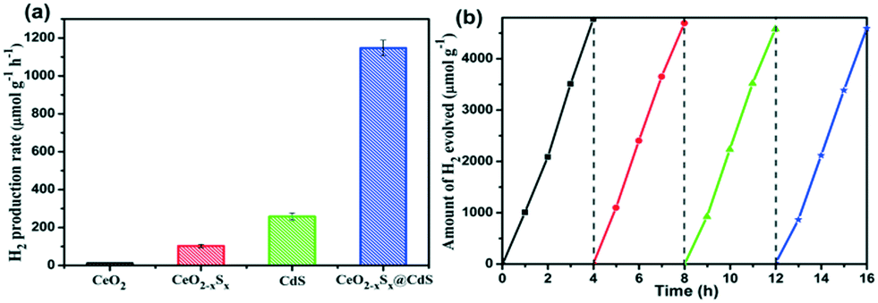 | ||
| Fig. 6 (a) Comparison of the H2 evolution rate of CeO2, CeO2−xSx, CdS and CeO2−xSx@CdS photocatalysts and (b) stability test of H2 evolution for CeO2−xSx@CdS under visible-light irradiation (λ > 420 nm). | ||
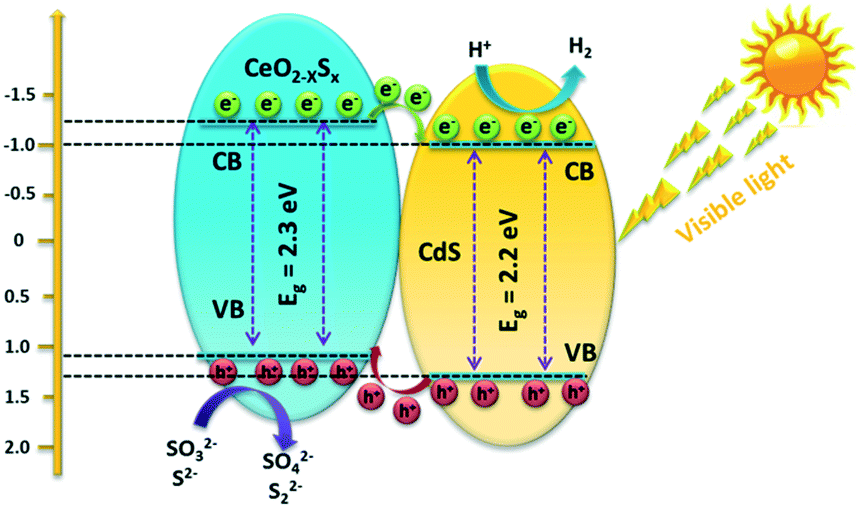
Based on the above material characterization and visible-light photocatalytic activity of the CeO2−xSx@CdS photocatalyst, a possible mechanism for photocatalytic H2 evolution over the CeO2−xSx@CdS photocatalyst is proposed (Scheme 2). The band gap of CeO2−xSx and CdS was calculated to be 2.3 eV and 2.2 eV, respectively (Fig. S11a and S11b†). The flat band potential of CeO2−xSx and CdS was calculated to be −1.2 eV and −1.0 eV according to the Mott–Schottky plots, respectively (Fig. S11c and S11d†). It is well known that the flat band potential is close to the conduction band in an n-type semiconductor.59 Accordingly, the valance band position of CeO2−xSx and CdS was calculated to be 1.1 eV and 1.2 eV, respectively. Thus, the CB position of CeO2−xSx is more negative than that of CdS, and it ensures that the photoexcited donor level is energetically higher. Under visible-light irradiation, CeO2−xSx absorbs photons and generates electro-hole pairs, and then the electrons from the CB of CeO2−xSx migrate to the low energetic CB of CdS. On the surface of CdS, the adsorbed H+ ions are reduced to H2 by the electrons, while the holes accumulated at the surface are quenched by SO32−/S2−. The excellent visible-light photocatalytic activity of CeO2−xSx@CdS could be ascribed to the introduced oxygen vacancies that create defect energy levels in the band gap and effectively facilitate the interface electron transfer, resulting in the electron transfer process being faster than the recombination of photoinduced electron–hole pairs between the CB and VB of CeO2−xSx.
 | ||
| Scheme 2 Schematic diagram of the proposed charge carrier transfer and H2 evolution mechanism over the CeO2−xSx@CdS photocatalyst under visible-light irradiation. | ||
4. Conclusion
In summary, the shape-controlled S-doped CeO2 hollow sphere decorated with an ultrathin CdS shell as a novel composite photocatalyst has been successfully fabricated by a “template + anion-exchange + chemical bath deposition” strategy. The photocatalytic activity could be remarkably improved by sulfur doping and the sensitization of ultrathin CdS shells. The CeO2−xSx@CdS composite exhibits excellent photocatalytic activity for both H2 evolution and organic pollutant degradation, which could be explained as follows: i) the doping of sulfur species into the CeO2 crystal structure can generate oxygen vacancies and reduce the band gap of the semiconductor; ii) the coating of the ultrathin CdS shell not only leads to the sensitization effect but also provides a large surface area and abundant active sites for the adsorption of reactants; iii) the composite structure of CeO2−xSx@CdS can promote the transfer of photogenerated electrons of CeO2−xSx to the surface of CdS, thus hindering the recombination of the generated electron–hole pairs. Therefore, it is expected that the as-fabricated CeO2−xSx@CdS nanocomposite could open a new avenue to design advanced photocatalysts for clean energy generation and environmental remediation.Conflicts of interest
There are no conflicts to declare.Acknowledgements
This research was financially supported by the Natural Science Foundation of China (Grant No. 21875048, 21576056, and 21576057), the Natural Science Foundation of Guangdong Province (Grant No. 2017A030311016), the Science and Technology Research Project of Guangdong Province (Grant No. 2016A010103043), the Major Scientific Project of Guangdong University (Grant No. 2017KZDXM059), the Science and Technology Research Project of Guangzhou (Grant No. 201607010232), and Guangzhou University's 2017 Training Program for Young Top-Notch Personnel (BJ201704).Notes and references
- X. B. Chen, L. Liu and F. Q. Huang, Chem. Soc. Rev., 2015, 44, 1861–1885 RSC.
- X. J. Lang, J. C. Zhao and X. D. Chen, Chem. Soc. Rev., 2016, 45, 3026–3038 RSC.
- Y. M. Shi and B. Zhang, Chem. Soc. Rev., 2016, 45, 1529–1541 RSC.
- N. N. Meng, J. Ren, Y. Liu, Y. Huang, T. Petit and B. Zhang, Energy Environ. Sci., 2018, 11, 566–571 RSC.
- O. Stroyuk, A. Raevskaya and N. Gaponik, Chem. Soc. Rev., 2018, 47, 5354–5422 RSC.
- J. Liu, Y. Liu, N. Y. Liu, Y. Z. Han, X. Zhang, H. Huang, Y. Lifshitz, S. T. Lee, J. Zhong and Z. H. Kang, Science, 2015, 347, 970–974 CrossRef CAS PubMed.
- D. Liu, J. Wang, X. J. Bai, R. L. Zong and Y. F. Zhu, Adv. Mater., 2016, 28, 7284–7290 CrossRef CAS PubMed.
- M. Zhu, Z. Sun, M. Fujitsuka and T. Majima, Angew. Chem., Int. Ed., 2018, 57, 2160–2164 CrossRef CAS PubMed.
- M. Zhu, X. Cai, M. Fujitsuka, J. Zhang and T. Majima, Angew. Chem., Int. Ed., 2017, 56, 2064–2068 CrossRef CAS PubMed.
- P. Y. Kuang, P. X. Zheng, Z. Q. Liu, J. L. Lei, H. Wu, N. Li and T. Y. Ma, Small, 2016, 12, 6735–6744 CrossRef CAS PubMed.
- R. Shi, H. F. Ye, F. Liang, Z. Wang, K. Li, Y. X. Weng, Z. S. Lin, W. F. Fu, C. M. Che and Y. Chen, Adv. Mater., 2018, 30, 1705941–1705947 CrossRef PubMed.
- D. Zheng, X.-N. Cao and X. Wang, Angew. Chem., Int. Ed., 2016, 55, 11512–11516 CrossRef CAS PubMed.
- C. M. Magdalane, K. Kaviyarasu, J. J. Vijaya, B. Siddhardha and B. Jeyaraj, J. Photochem. Photobiol., B, 2016, 163, 77–86 CrossRef CAS PubMed.
- C. M. Magdalane, K. Kaviyarasu, J. J. Vijaya, C. Jayakumar, M. Maaza and B. Jeyaraj, J. Photochem. Photobiol., B, 2017, 169, 110–123 CrossRef PubMed.
- K. Kasinathan, J. Kennedy, M. Elayaperumal, M. Henini and M. Malik, Sci. Rep., 2016, 6, 38064–38076 CrossRef CAS PubMed.
- T. Montini, M. Melchionna, M. Monai and P. Fornasiero, Chem. Rev., 2016, 116, 5987–6041 CrossRef CAS PubMed.
- J. A. Rodriguez, D. C. Grinter, Z. Liu, R. M. Palomino and S. D. Senanayake, Chem. Soc. Rev., 2017, 46, 1824–1841 RSC.
- J. Paier, C. Penschke and J. Sauer, Chem. Rev., 2013, 113, 3949–3985 CrossRef CAS PubMed.
- C. M. Magdalane, K. Kaviyarasu, J. J. Vijaya, B. Siddhardha, B. Jeyaraj, J. Kennedy and M. Maaza, J. Alloys Compd., 2017, 727, 1324–1337 CrossRef CAS.
- P. I. Rajan, J. J. Vijaya, S. K. Jesudoss, K. Kaviyarasu, S. C. Lee, L. J. Kennedy, R. Jothiramalingam, H. A. Al-Lohedan and M. M. Abdullah, R. Soc. Open Sci., 2018, 5, 171430–171439 CrossRef PubMed.
- K. Kaviyarasu, E. Manikandan, Z. Y. Nuru and M. Maaza, Mater. Lett., 2015, 160, 61–63 CrossRef CAS.
- Y. T. Xiao, Y. J. Chen, Y. Xie, G. H. Tian, S. E. Guo, T. R. Han and H. G. Fu, Chem. Commun., 2016, 52, 2521–2524 RSC.
- H. J. Jung, S. H. Kye, H. J. Kang, H. J. Yang, J. B. Yoo, K. H. Lee and N. H. Hur, Appl. Catal., A, 2018, 558, 9–17 CrossRef CAS.
- T. Ye, W. M. Huang, L. M. Zeng, M. L. Li and J. L. Shi, Appl. Catal., B, 2017, 210, 141–148 CrossRef CAS.
- S. L. Xie, Z. L. Wang, F. L. Cheng, P. Zhang, W. J. Mai and Y. X. Tong, Nano Energy, 2017, 34, 313–337 CrossRef CAS.
- S. Sultana, S. Mansingh, M. Scurrell and K. M. Parida, Inorg. Chem., 2017, 56, 12297–12307 CrossRef CAS PubMed.
- J.-J. Li, E.-Q. Yu, S.-C. Cai, X. Chen, J. Chen, H.-P. Jia and Y.-J. Xu, Appl. Catal., B, 2018, 240, 141–152 CrossRef.
- W. X. Zou, B. Deng, X. X. Hu, Y. P. Zhou, Y. Pu, S. H. Yu, K. L. Ma, J. F. Sun, H. Q. Wan and L. Dong, Appl. Catal., B, 2018, 238, 111–118 CrossRef CAS.
- W. Y. Lei, T. T. Zhang, L. Gu, P. Liu, J. A. Rodriguez, G. Liu and M. H. Liu, ACS Catal., 2015, 5, 4385–4393 CrossRef CAS.
- A. D. Liyanage, S. D. Perera, K. Tan, Y. Chabal and K. J. Balkus, ACS Catal., 2014, 4, 577–584 CrossRef CAS.
- T. Q. Lin, C. Y. Yang, Z. Wang, H. Yin, X. J. Lü, F. Q. Huang, J. H. Lin, X. M. Xie and M. H. Jiang, Energy Environ. Sci., 2014, 7, 967–972 RSC.
- C. Z. Sun, H. Zhang, H. Liu, X. X. Zheng, W. X. Zou, L. Dong and L. Qi, Appl. Catal., B, 2018, 235, 66–74 CrossRef CAS.
- B. Liu, L. M. Liu, X. F. Lang, H. Y. Wang, X. W. Lou and E. S. Aydil, Energy Environ. Sci., 2014, 7, 2592–2597 RSC.
- Y. S. Si, M. Chen and L. M. Wu, Chem. Soc. Rev., 2016, 45, 690–714 RSC.
- R. B. Wei, Z. L. Huang, G. H. Gu, Z. Wang, L. X. Zeng, Y. B. Chen and Z. Q. Liu, Appl. Catal., B, 2018, 231, 101–107 CrossRef CAS.
- Q. Wu, H. F. Zhao, F. Huang, J. Hou, H. B. Cao, Z. Y. Liu, S. L. Peng and G. Z. Cao, J. Phys. Chem. C, 2017, 121, 18430–18438 CrossRef CAS.
- N. Li, H. Y. Zhao, Y. Zhang, Z. Q. Liu, X. Y. Gong and Y. P. Du, CrystEngComm, 2016, 18, 4158–4164 RSC.
- X. Gong, Y. Q. Gu, N. Li, H. Zhao, C. J. Jia and Y. Du, Inorg. Chem., 2016, 55, 3992–3999 CrossRef CAS PubMed.
- B. Xu, Q. T. Zhang, S. S. Yuan, M. Zhang and T. Ohno, Appl. Catal., B, 2016, 183, 361–370 CrossRef CAS.
- Z. Q. Cui, W. K. Wang, C. J. Zhao, C. Chen, M. M. Han, G. Z. Wang, Y. X. Zhang, H. M. Zhang and H. J. Zhao, ACS Appl. Mater. Interfaces, 2018, 10, 31394–31403 CrossRef CAS PubMed.
- A. Naldoni, M. Allieta, S. Santangelo, M. Marelli, F. Fabbri, S. Cappelli, C. L. Bianchi, R. Psaro and V. D. Santo, J. Am. Chem. Soc., 2012, 134, 7600–7603 CrossRef CAS PubMed.
- N. Zhang, X. Y. Li, H. C. Ye, S. M. Chen, H. X. Ju, D. B. Liu, Y. Lin, W. Ye, C. M. Wang, Q. Xu, J. F. Zhu, L. Song, J. Jiang and Y. J. Xiong, J. Am. Chem. Soc., 2016, 138, 8928–8935 CrossRef CAS.
- B. Hillary, P. Sudarsanam, M. H. Amin and S. K. Bhargava, Langmuir, 2017, 33, 1743–1750 CrossRef CAS PubMed.
- Z. J. Tan, P. R. Liu, H. M. Zhang, Y. Wang, M. Al-Mamun, H. G. Yang, D. Wang, Z. Y. Tang and H. J. Zhao, Chem. Commun., 2015, 51, 5695–5697 RSC.
- S. S. Gu, Y. N. Chen, X. Z. Yuan, H. Wang, X. H. Chen, Y. Liu, Q. Jiang, Z. B. Wu and G. M. Zeng, RSC Adv., 2015, 5, 79556–79564 RSC.
- N. Zhang, S. Xie, B. Weng and Y.-J. Xu, J. Mater. Chem. A, 2016, 4, 18804–18814 RSC.
- B. C. Qiu, Q. H. Zhu, M. M. Du, L. G. Fan, M. Y. Xing and J. L. Zhang, Angew. Chem., Int. Ed., 2017, 56, 2684–2688 CrossRef CAS PubMed.
- X. J. Wen, C. G. Niu, L. Zhang, C. Liang and G. M. Zeng, Appl. Catal., A, 2018, 221, 701–714 CrossRef CAS.
- N. Tian, H. W. Huang, C. Y. Liu, F. Dong, T. R. Zhang, X. Du, S. X. Yu and Y. H. Zhang, J. Mater. Chem. A, 2015, 3, 17120–17129 RSC.
- J. S. Zhang, J. H. Sun, K. Maeda, K. Domen, P. Liu, M. Antonietti, X. Z. Fu and X. C. Wang, Energy Environ. Sci., 2011, 4, 675–678 RSC.
- P. Sudarsanam, B. Mallesham, D. N. Durgasri and B. M. Reddy, J. Ind. Eng. Chem., 2014, 20, 3115–3121 CrossRef CAS.
- A. D. Mani, S. Nandy and C. Subrahmanyam, J. Environ. Chem. Eng., 2015, 3, 2350–2357 CrossRef.
- L. Chen, D. W. Meng, X. L. Wu, A. Wang, J. X. Wang, Y. Q. Wang and M. H. Yu, J. Phys. Chem. C, 2016, 120, 18548–18559 CrossRef CAS.
- J. Han, J. Meeprasert, P. Maitarad, S. Nammuangruk, L. Y. Shi and D. S. Zhang, J. Phys. Chem. C, 2016, 120, 1523–1533 CrossRef CAS.
- X. Li, S. W. Liu, K. Fan, Z. Q. Liu, B. Song and J. G. Yu, Adv. Energy Mater., 2018, 8, 1800101–1800110 CrossRef.
- S. Y. Chae, S. J. Park, S. G. Han, H. Jung, C. W. Kim, C. Jeong, O. S. Joo, B. K. Min and Y. J. Hwang, J. Am. Chem. Soc., 2016, 138, 15673–15681 CrossRef CAS PubMed.
- W. Q. Wei, D. Liu, Z. Wei and Y. F. Zhu, ACS Catal., 2016, 7, 652–663 CrossRef.
- R. B. Wei, P. Y. Kuang, H. Cheng, Y. B. Chen, J. Y. Long, M. Y. Zhang and Z. Q. Liu, ACS Sustainable Chem. Eng., 2017, 5, 4249–4257 CrossRef CAS.
- Z. Zhang and J. T. Yates, Chem. Rev., 2012, 112, 5520–5551 CrossRef CAS PubMed.
Footnote |
| † Electronic supplementary information (ESI) available. See DOI: 10.1039/c8cy02206b |
| This journal is © The Royal Society of Chemistry 2019 |